


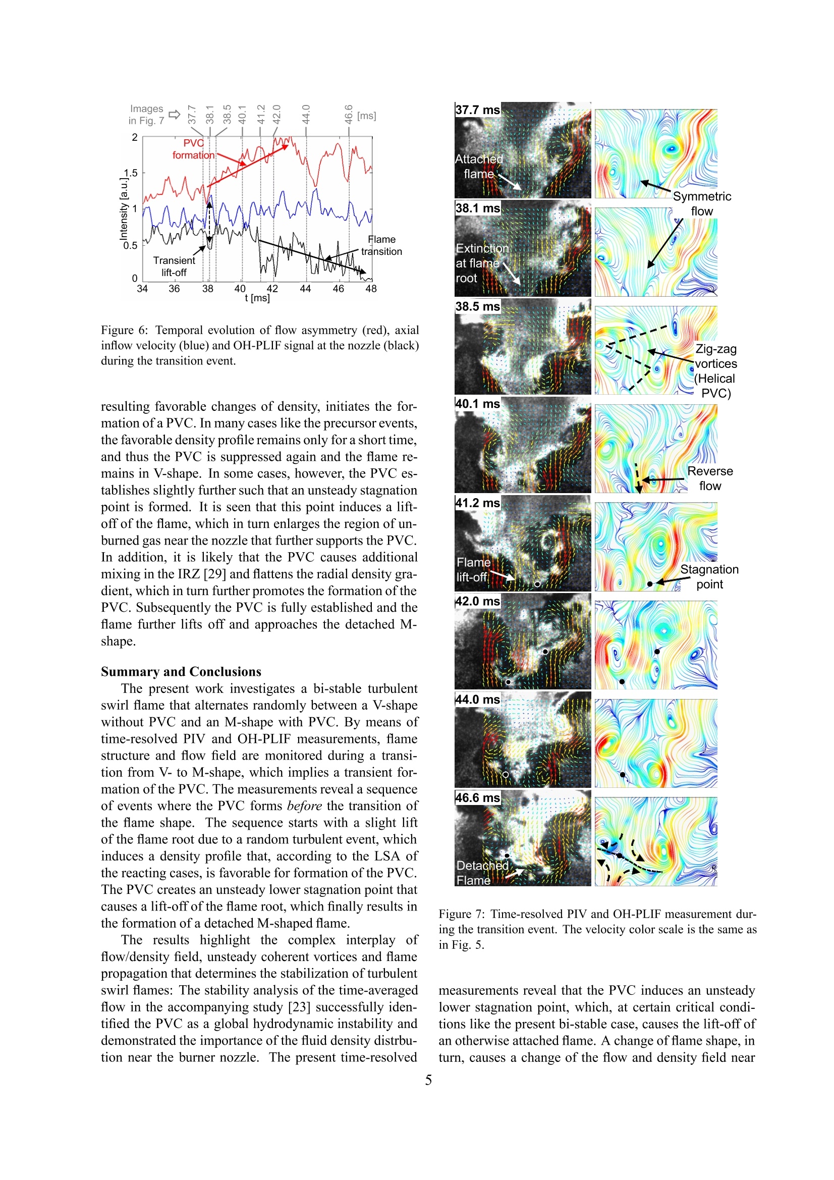
利用LaVisin公司提供的高速CMOS相机和高速图像增强器HS-IRO构成一套时间分辨PIV和PLIF联合测试系统,用于分析双稳态湍动旋流火焰中进动涡核(PVC)形成和火焰形状变化之间瞬态耦合过程。
方案详情

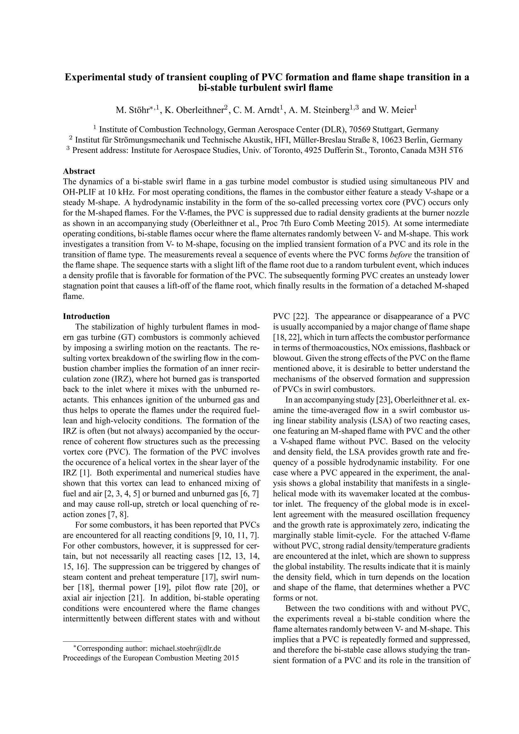
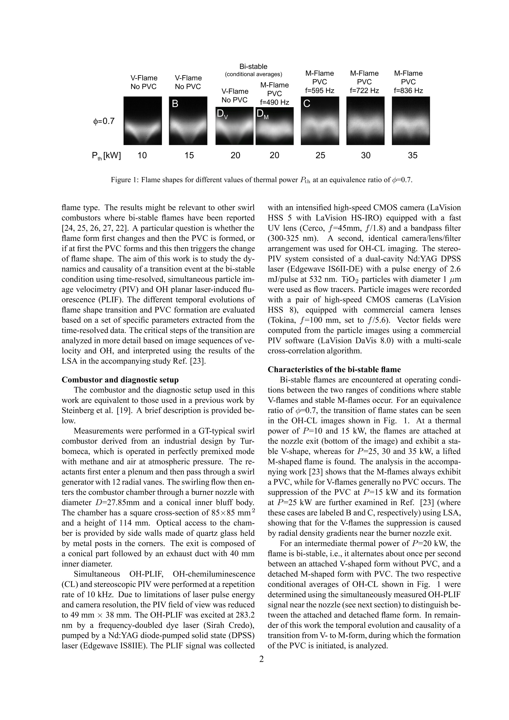
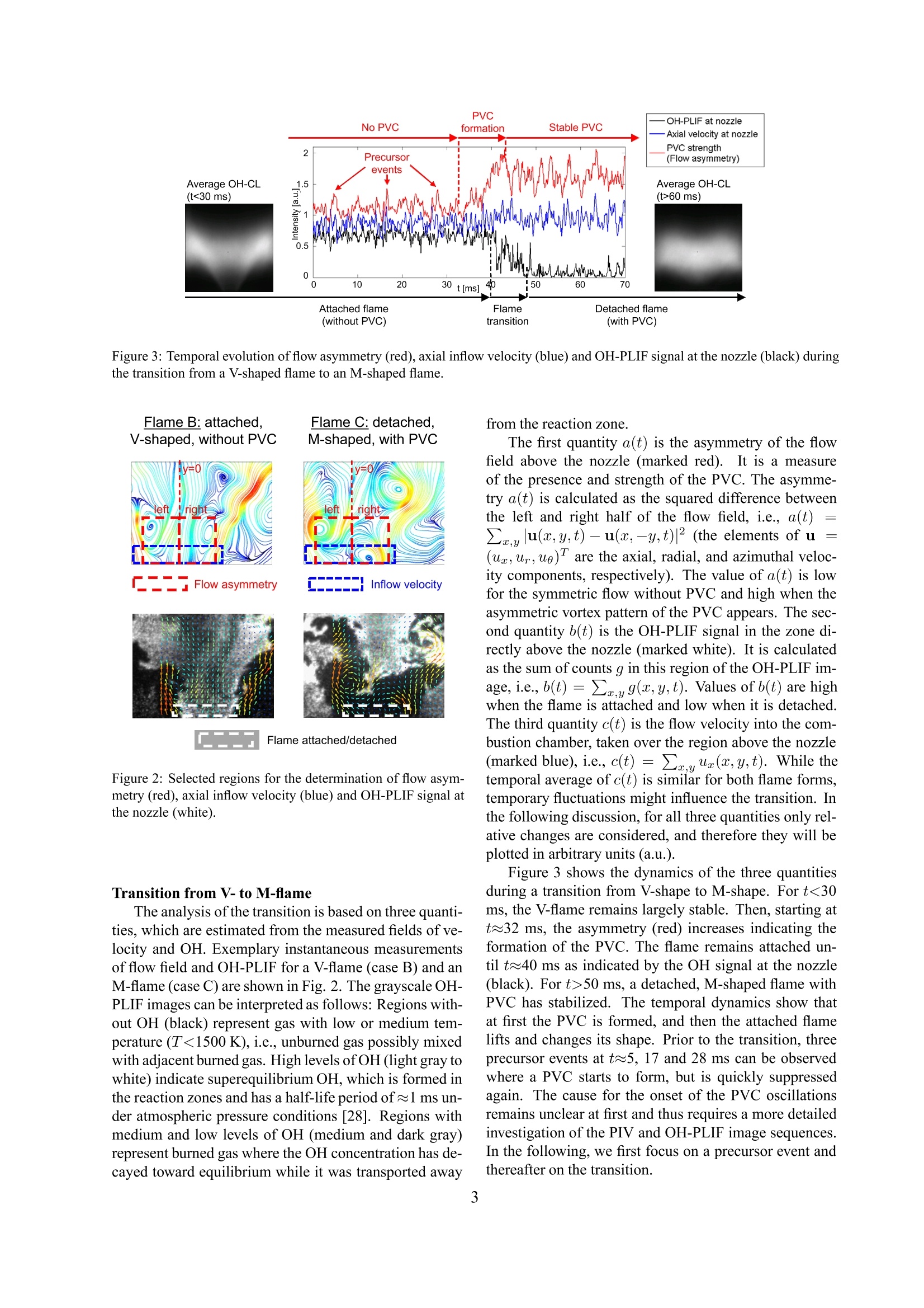
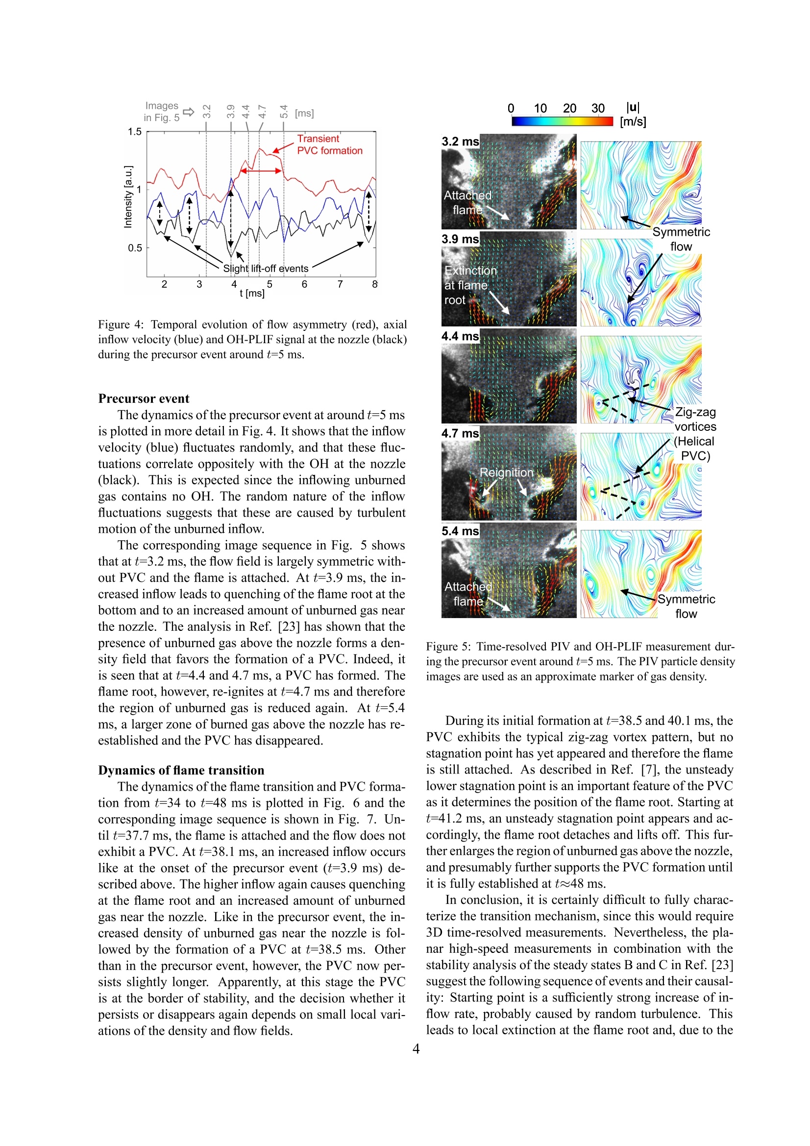
Experimental study of transient coupling of PVC formation and flame shape transition in abi-stable turbulent swirl flame M. Stohr*,l, K. Oberleithner?, C. M. Arndt, A. M. Steinberg1,3 and W. Meierl Institute of Combustion Technology, German Aerospace Center (DLR), 70569 Stuttgart, Germany 2Innst ir Stromungsmechanik und Technische Akustik, HFI, Muller-Breslau StraBe 8, 10623 Berlin, Germany Present address: Institute for Aerospace Studies, Univ. of Toronto, 4925 Dufferin St., Toronto, Canada M3H 5T6 Abstract The dynamics of a bi-stable swirl flame in a gas turbine model combustor is studied using simultaneous PIV andOH-PLIF at 10kHz. For most operating conditions, the flames in the combustor either feature a steady V-shape or asteady M-shape. A hydrodynamic instability in the form of the so-called precessing vortex core (PVC) occurs onlyfor the M-shaped flames. For the V-flames, the PVC is suppressed due to radial density gradients at the burner nozzleas shown in an accompanying study (Oberleithner et al., Proc 7th Euro Comb Meeting 2015). At some intermediateoperating conditions, bi-stable flames occur where the flame alternates randomly between V-and M-shape. This workinvestigates a transition from V-to M-shape, focusing on the implied transient formation of a PVC and its role in thetransition of flame type. The measurements reveal a sequence of events where the PVC forms before the transition ofthe flame shape. The sequence starts with a slight lift of the flame root due to a random turbulent event, which inducesa density profile that is favorable for formation of the PVC. The subsequently forming PVC creates an unsteady lowerstagnation point that causes a lift-off of the flame root, which finally results in the formation of a detached M-shapedflame. Introduction The stabilization of highly turbulent flames in mod-ern gas turbine (GT) combustors is commonly achievedby imposing a swirling motion on the reactants. The re-sulting vortex breakdown of the swirling flow in the com-bustion chamber implies the formation of an inner recir-culation zone (IRZ), where hot burned gas is transportedback to the inlet where it mixes with the unburned re-actants. This enhances ignition of the unburned gas andthus helps to operate the flames under the required fuel-lean and high-velocity conditions. The formation of theIRZ is often (but not always) accompanied by the occur-rence of coherent flow structures such as the precessingvortex core (PVC). The formation of the PVC involvesthe occurence of a helical vortex in the shear layer of theIRZ [1]. Both experimental and numerical studies haveshown that this vortex can lead to enhanced mixing offuel and air [2, 3, 4, 5] or burned and unburned gas [6, 7]and may cause roll-up, stretch or local quenching of re-action zones [7, 8]. For some combustors, it has been reported that PVCsare encountered for all reacting conditions [9, 10, 11, 7].For other combustors, however, it is suppressed for cer-tain, but not necessarily all reacting cases [12, 13, 14,15, 16]. The suppression can be triggered by changes ofsteam content and preheat temperature [17], swirl num-ber [18], thermal power [19], pilot flow rate [20], oraxial air injection [21]. In addition, bi-stable operatingconditions were encountered where the flame changesintermittently between different states with and without ( *Corresponding author: m ichael.stoehr@dlr.de Proceedings of the European Combustion Meeting 2015 ) PVC [22]. The appearance or disappearance of a PVCis usually accompanied by a major change of flame shape[18, 22], which in turn affects the combustor performancein terms of thermoacoustics, NOx emissions, flashback orblowout. Given the strong effects of the PVC on the flamementioned above, it is desirable to better understand themechanisms of the observed formation and suppressionof PVCs in swirl combustors. In an accompanying study [23], Oberleithner et al. ex-amine the time-averaged flow in a swirl combustor us-ing linear stability analysis (LSA) of two reacting cases,one featuring an M-shaped flame with PVC and the othera V-shaped flame without PVC. Based on the velocityand density field, the LSA provides growth rate and fre-quency of a possible hydrodynamic instability. For onecase where a PVC appeared in the experiment, the anal-ysis shows a global instability that manifests in a single-helical mode with its wavemaker located at the combus-tor inlet. The frequency of the global mode is in excel-lent agreement with the measured oscillation frequencyand the growth rate is approximately zero, indicating themarginally stable limit-cycle. For the attached V-flamewithout PVC, strong radial density/temperature gradientsare encountered at the inlet, which are shown to suppressthe global instability. The results indicate that it is mainlythe density field, which in turn depends on the locationand shape of the flame, that determines whether a PVCforms or not. Between the two conditions with and without PVC,the experiments reveal a bi-stable condition where theflame alternates randomly between V- and M-shape. Thisimplies that a PVC is repeatedly formed and suppressed,and therefore the bi-stable case allows studying the tran-sient formation of a PVC and its role in the transition of Figure 1: Flame shapes for different values of thermal power Pth at an equivalence ratio of o=0.7. flame type. The results might be relevant to other swirlcombustors where bi-stable flames have been reported[24,25,26,27,221. A particular question is whether theflame form first changes and then the PVC is formed, orif at first the PVC forms and this then triggers the changeof flame shape. The aim of this work is to study the dy-namics and causality of a transition event at the bi-stablecondition using time-resolved, simultaneous particle im-age velocimetry (PIV) and OH planar laser-induced flu-orescence (PLIF). The different temporal evolutions offlame shape transition and PVC formation are evaluatedbased on a set of specific parameters extracted from thetime-resolved data. The critical steps of the transition areanalyzed in more detail based on image sequences of ve-locity and OH, and interpreted using the results of theLSA in the accompanying study Ref. [23]. Combustor and diagnostic setup The combustor and the diagnostic setup used in thiswork are equivalent to those used in a previous work bySteinberg et al. [19]. A brief description is provided be-low. Measurements were performed in a GT-typical swirlcombustor derived from an industrial design by Tur-bomeca, which is operated in perfectly premixed modewith methane and air at atmospheric pressure. The re-actants first enter a plenum and then pass through a swirlgenerator with 12 radial vanes. The swirling flow then en-ters the combustor chamber through a burner nozzle withdiameter D=27.85mm and a conical inner bluff body.The chamber has a square cross-section of 85×85 mm"and a height of 114 mm. Optical access to the cham-ber is provided by side walls made of quartz glass heldby metal posts in the corners. The exit is composed ofa conical part followed by an exhaust duct with 40 mminner diameter. .Simultaneous OH-PLIF..OH-chemiluminescence(CL) and stereoscopic PIV were performed at a repetitionrate of 10 kHz. Due to limitations of laser pulse energyand camera resolution, the PIV field of view was reducedto 49 mm × 38 mm. The OH-PLIF was excited at 283.2nm by a frequency-doubled dye laser (Sirah Credo),pumped by a Nd:YAG diode-pumped solid state (DPSS)laser (Edgewave IS8IIE). The PLIF signal was collected with an intensified high-speed CMOS camera (LaVisionHSS 5 with LaVision HS-IRO) equipped with a fastUV lens (Cerco, f=45mm, f/1.8) and a bandpass filter(300-325 nm)). A second, identical camera/lens/filterarrangement was used for OH-CL imaging. The stereo-PIV system consisted of a dual-cavity Nd:YAG DPSSlaser (Edgewave IS6II-DE) with a pulse energy of 2.6mJ/pulse at 532 nm. TiO2 particles with diameter 1 umwere used as flow tracers. Particle images were recordedwith a pair of high-speed CMOS cameras (LaVisionHSS 8), equipped with commercial camera lenses(Tokina, f=100 mm, set to f/5.6). Vector fields werecomputed from the particle images using a commercialPIV software (LaVision DaVis 8.0) with a multi-scalecross-correlation algorithm. Characteristics of the bi-stable flame Bi-stable flames are encountered at operating condi-tions between the two ranges of conditions where stableV-flames and stable M-flames occur. For an equivalenceratio of o=0.7, the transition of flame states can be seenin the OH-CL images shown in Fig.1. At a thermalpower of P=10 and 15 kW, the flames are attached atthe nozzle exit (bottom of the image) and exhibit a sta-ble V-shape, whereas for P=25, 30 and 35 kW, a liftedM-shaped flame is found. The analysis in the accompa-nying work [23] shows that the M-flames always exhibita PVC, while for V-flames generally no PVC occurs. Thesuppression of the PVC at P=15 kW and its formationat P=25 kW are further examined in Ref. [23] (wherethese cases are labeled B and C, respectively) using LSA,showing that for the V-flames the suppression is causedby radial density gradients near the burner nozzle exit. For an intermediate thermal power of P=20 kW, theflame is bi-stable, i.e., it alternates about once per secondbetween an attached V-shaped form without PVC, and adetached M-shaped form with PVC. The two respectiveconditional averages of OH-CL shown in Fig. 1 wedetermined using the simultaneously measured OH-PLIFsignal near the nozzle (see next section) to distinguish be-tween the attached and detached flame form. In remain-der of this work the temporal evolution and causality of atransition from V-to M-form, during which the formationof the PVC is initiated, is analyzed. Figure 3: Temporal evolution of flow asymmetry (red), axial inflow velocity (blue) and OH-PLIF signal at the nozzle (black) duringthe transition from a V-shaped flame to an M-shaped flame. Flame B: attached. Flame C: detached, Figure 2: Selected regions for the determination of flow asym-metry (red), axial inflow velocity (blue) and OH-PLIF signal atthe nozzle (white). Transition from V-to M-flame The analysis of the transition is based on three quanti-ties. which are estimated from the measured fields of ve-locity and OH. Exemplary instantaneous measurementsof flow field and OH-PLIF for a V-flame (case B) and anM-flame (case C) are shown in Fig. 2. The grayscale OH-PLIF images can be interpreted as follows: Regions with-out OH (black) represent gas with low or medium tem-perature (T<1500 K),i.e., unburned gas possibly mixedwith adjacent burned gas. High levels ofOH (light gray towhite) indicate superequilibrium OH, which is formed inthe reaction zones and has a half-life period of ≈1 ms un-der atmospheric pressure conditions [28]. Regions withmedium and low levels of OH (medium and dark gray)represent burned gas where the OH concentration has de-cayed toward equilibrium while it was transported away from the reaction zone. The first quantity a(t) is the asymmetry of the flowfield above the nozzle (marked red).It is a measureof the presence and strength of the PVC. The asymme-try a(t) is calculated as the squared difference betweenthe left and right half of the flow field, i.e., a(t)——Zxylu(a,y,t)-u(z,-y,t)|2 (the elements of uL =(ua;Ur,ue) are the axial,(uc,ur,u0) radial, and azimuthal veloc-ity components, respectively). The value of a(t) is lowfor the symmetric flow without PVC and high when theasymmetric vortex pattern of the PVC appears. The sec-ond quantity b(t) is the OH-PLIF signal in the zone di-rectly above the nozzle (marked white). It is calculatedas the sum of counts g in this region of the OH-PLIF im-age, i.e.,b(t)=r.u9(a,y,t). Values of b(t) are highwhen the flame is attached and low when it is detached.The third quantity c(t) is the flow velocity into the com-bustion chamber, taken over the region above the nozzle(marked blue), i.e., c(t)=ryUr(a,y,t). While thetemporal average of c(t) is similar for both flame forms,temporary fluctuations might influence the transition. Inthe following discussion, for all three quantities only rel-ative changes are considered, and therefore they will beplotted in arbitrary units (a.u.). Figure 3 shows the dynamics of the three quantitiesduring a transition from V-shape to M-shape. For t<30ms, the V-flame remains largely stable. Then, starting att≈32 ms, the asymmetry (red) increases indicating theformation of the PVC. The flame remains attached un-til t40 ms as indicated by the OH signal at the nozzle(black). For t>50 ms, a detached,M-shaped flame withPVC has stabilized. The temporal dynamics show thatat first the PVC is formed, and then the attached flamelifts and changes its shape. Prior to the transition, threeprecursor events at t~5, 17 and 28 ms can be observedwhere a PVC starts to form, but is quickly suppressedagain. The cause for the onset of the PVC oscillationsremains unclear at first and thus requires a more detailedinvestigation of the PIV and OH-PLIF image sequences.In the following, we first focus on a precursor event andthereafter on the transition. Figure 4: Temporal evolution of flow asymmetry (red), axialinflow velocity (blue) and OH-PLIF signal at the nozzle (black)during the precursor event around t=5 ms. Precursor event The dynamics of the precursor event at around t=5 msis plotted in more detail in Fig. 4. It shows that the inflowvelocity (blue) fluctuates randomly, and that these fluc-tuations correlate oppositely with the OH at the nozzle(black). This is expected since the inflowing unburnedgas contains no OH. The random nature of the inflowfluctuations suggests that these are caused by turbulentmotion of the unburned inflow. The corresponding image sequence in Fig. 5 showsthat at t=3.2 ms, the flow field is largely symmetric with-out PVC and the flame is attached. At t=3.9 ms, the in-creased inflow leads to quenching of the flame root at thebottom and to an increased amount of unburned gas nearthe nozzle. The analysis in Ref. [23] has shown that thepresence of unburned gas above the nozzle forms a den-sity field that favors the formation of a PVC. Indeed, itis seen that at t=4.4 and 4.7 ms, a PVC has formed. Theflame root, however, re-ignites at t=4.7 ms and thereforethe region of unburned gas is reduced again. At t=5.4ms, a larger zone of burned gas above the nozzle has re-established and the PVC has disappeared. Dynamics of flame transition The dynamics of the flame transition and PVC forma-tion from t=34 to t=48 ms is plotted in Fig. 6 and thecorresponding image sequence is shown in Fig. 7. Un-til t=37.7 ms, the flame is attached and the flow does notexhibit a PVC. At t=38.1 ms, an increased inflow occurslike at the onset of the precursor event (t=3.9 ms) de-scribed above. The higher inflow again causes quenchingat the flame root and an increased amount of unburnedgas near the nozzle. Like in the precursor event, the in-creased density of unburned gas near the nozzle is fol-lowed by the formation of a PVC at t=38.5 ms. Otherthan in the precursor event,however, the PVC now per-sists slightly longer. Apparently, at this stage the PVCis at the border of stability, and the decision whether itpersists or disappears again depends on small local vari-ations of the density and flow fields. 0 10 20 30 |u| Figure 5: Time-resolved PIV and OH-PLIF measurement dur-ing the precursor event around t=5 ms. The PIV particle densityimages are used as an approximate marker of gas density. During its initial formation at t=38.5 and 40.1 ms, thePVC exhibits the typical zig-zag vortex pattern, but nostagnation point has yet appeared and therefore the flameis still attached. As described in Ref. [7], the unsteadylower stagnation point is an important feature of the PVCas it determines the position of the flame root. Starting att=41.2 ms, an unsteady stagnation point appears and ac-cordingly, the flame root detaches and lifts off. This fur-ther enlarges the region ofunburned gas above the nozzle,and presumably further supports the PVC formation untilit is fully established at t≈48 ms. In conclusion, it is certainly difficult to fully charac-terize the transition mechanism, since this would require3D time-resolved measurements. Nevertheless, the pla-nar high-speed measurements in combination with thestability analysis of the steady states B and C in Ref. [23]suggest the following sequence ofevents and their causal-ity: Starting point is a sufficiently strong increase of in-flow rate, probably caused by random turbulence. Thisleads to local extinction at the flame root and. due to the Figure 6: Temporal evolution of flow asymmetry (red), axialinflow velocity (blue) and OH-PLIF signal at the nozzle (black)during the transition event. resulting favorable changes of density, initiates the for-mation of a PVC. In many cases like the precursor events,the favorable density profile remains only for a short time,and thus the PVC is suppressed again and the flame re-mains in V-shape. In some cases, however, the PVC es-tablishes slightly further such that an unsteady stagnationpoint is formed. It is seen that this point induces a lift-off of the flame, which in turn enlarges the region of un-burned gas near the nozzle that further supports the PVC.In addition, it is likely that the PVC causes additionalmixing in the IRZ [29] and flattens the radial density gra-dient, which in turn further promotes the formation of thePVC. Subsequently the PVC is fully established and theflame further lifts off and approaches the detached M-shape. Summary and Conclusions The present work investigates a bi-stable turbulentswirl flame that alternates randomly between a V-shapewithout PVC and an M-shape with PVC. By means oftime-resolved PIV and OH-PLIF measurements, flamestructure and flow field are monitored during a transi-tion from V- to M-shape, which implies a transient for-mation of the PVC. The measurements reveal a sequenceof events where the PVC forms before the transition ofthe flame shape. The sequence starts with a slight liftof the flame root due to a random turbulent event, whichinduces a density profile that, according to the LSA ofthe reacting cases, is favorable for formation of the PVC.The PVC creates an unsteady lower stagnation point thatcauses a lift-off of the flame root, which finally results inthe formation of a detached M-shaped flame. The results highlight the complex interplay offlow/density field, unsteady coherent vortices and flamepropagation that determines the stabilization of turbulentswirl flames: The stability analysis of the time-averagedflow in the accompanying study [23] successfully iden-tified the PVC as a global hydrodynamic instability anddemonstrated the importance of the fluid density distrbu-tion near the burner nozzle. The present time-resolved 37.7 ms Figure 7: Time-resolved PIV and OH-PLIF measurement dur-ing the transition event. The velocity color scale is the same asin Fig. 5. measurements reveal that the PVC induces an unsteadylower stagnation point, which, at certain critical condi-tions like the present bi-stable case, causes the lift-off ofan otherwise attached flame. A change of flame shape, inturn, causes a change of the flow and density field near the burner nozzle. Given the essential role of the PVC inthis interplay, the analysis of the hydrodynamic stabilityof the reacting swirling flow is a critical step in the designof a swirl combustor. ( References ) ( [1 ] N. Syred, Prog. Energy Combust. Sci. 32 (2006) 93 -161. ) ( [2] M. Freitag, K. M., M. Gregor, D. Geyer, C. Schnei- der, A. D reizler, J. J anicka, Int. J . Heat Fluid F l ow 27(2006)636-643. ) ( [3] J. F rohlich, M. Garcia-Villalba,W. Rodi, Flow T u r-bul. Comb. 80(2008) 47-59. ) ( [4] D. Galley, S. Ducruix, F. Lacas, D. Veynante, Com-bust. Flame 158 (2011)155-171. ) ( [5] M. Stohr, C. Arndt, W. M eier, Proc. Combust. Inst. 35(2015)3327-3335. ) ( [6] M. Stohr, R. Sadanandan, W. Meier, Exp. F l uids 51(2011)1153-1167. ) ( [7] M . Stohr, I . Boxx, C. D. Carter, W. Meier, Combust. Flame 159 (2012)2636-2649. ) ( [8] M . Stohr, C . A rndt, W.Meier, Pr o c. Co m bust. Inst.34(2013)3107-3115. ) ( [9] P . M. Anacleto, E. C. Fernandes, M. V. Heitor, S. I.Shtork, Combust. Sci. T echnol. 175 ( 2003) 1369-1388. ) ( [10] N. Patel, S . Menon, Combust. Flame 1 53 (2008)228-257. ) ( [11] P . Fokaides, M. W ei, M . K e rn, N . Zarzalis, Flow T urbul. Comb. 83 (2009)511 - 533. ) ( [12] L . Selle, G. L artigue, T . Poinsot, R. Koch, K .-U.Schildmacher, W. K rebs, B . P rade, P . Kaufmann,D. Veynante, Combust. Flame 137 (2004) 489-505. ) ( [13] C . S chneider, A . D reizler, J. Janicka, Flow Turbul.Comb. 74(2005)103- 1 27. ) ( [14] K.-U. Schildmacher, R. Koch, H .-J. Bauer, FlowTurbul. Comb. 76 (2006)177 - 197. ) ( [15] M. F reitag, J. J anicka, Proc. C ombust. Inst. 31(2007)1477-1485. ) ( [16] A . D e, S. Zhu, S. Acharya, J. Eng. Gas Turb. Power132(2010)071503. ) ( [ 1 7] S. Terhaar, K. Oberleithner, C. O.Paschereit, Com-bust. Sci. Technol.186 (2014). ) ( [ 1 8] C . Duwig, L. F uchs, Phys. Fluids 19 (2007)5103. ) ( [19] A. M. S teinberg, C. M. Arndt, W. Meier, P roc.Combust. Inst.34(2013)3117-3125. ) ( [20] A. X. S engissen, A . V . Giauque, G. S. Staffelbach,M. P orta, W. K rebs, P . Kaufmann, T . J . P oinsot,Proc. Combust. I nst. 31 (2007) 1729-1736. ) ( [21] S. Terhaar, T. G. Reichel, C. Schrodinger, L. Rukes,C. O . Paschereit, K . O berleithner, J P ropul P ower 31 ( 2014)219-229. ) ( [22] S. Hermeth, G . Staffelbach, L. Y . M. Gicquel,V. Anisimov, C. Cirigliano, T.Poinsot, C ombust.Flame 161 (2014)184-196. ) ( [23] K. Oberleithner, M. Stohr, S. H. Im, C . O.Paschereit, in : Proceedings of the 7th EuropeanCombustion Meeting (2015) Budapest, Hungary. ) ( [24] W . P olifke, A. Fischer, T. Sattelmayer, J . Eng. Gas T urb. Power 1 25 (2003) 20-27. ) ( [25] D. Fritsche , M. Furi, K. Boulouchos, Combust.Flame 1 51 (2007)29-36. ) ( [26] F . Biagioli, F. Guthe, B. Schuermans, Exp. Therm.Fluid Sci. 32 (2008) 1344-1353. ) ( [27] T. F . Guiberti, D . D urox, P. S c ouflaire, T . Schuller,F. Biagioli, F. Githe, B. Schuermans, Proc . Com-bust. Inst. 35 (2015) 1 385-1392. ) ( [28] R. Sadanandan, M. Stohr, W. Meier, Appl. Phys.B90(2008)609-618. ) ( [29] S. Terhaar, O. Kruger, C . O. P a schereit, J ournalof Engineering for Gas Turbines and Power 137(2015)041503. ) The dynamics of a bi-stable swirl flame in a gas turbine model combustor is studied using simultaneous PIV andOH-PLIF at 10 kHz. For most operating conditions, the flames in the combustor either feature a steady V-shape or asteady M-shape. A hydrodynamic instability in the form of the so-called precessing vortex core (PVC) occurs onlyfor the M-shaped flames. For the V-flames, the PVC is suppressed due to radial density gradients at the burner nozzleas shown in an accompanying study (Oberleithner et al., Proc 7th Euro Comb Meeting 2015). At some intermediateoperating conditions, bi-stable flames occur where the flame alternates randomly between V- and M-shape. This workinvestigates a transition from V- to M-shape, focusing on the implied transient formation of a PVC and its role in thetransition of flame type. The measurements reveal a sequence of events where the PVC forms before the transition ofthe flame shape. The sequence starts with a slight lift of the flame root due to a random turbulent event, which inducesa density profile that is favorable for formation of the PVC. The subsequently forming PVC creates an unsteady lowerstagnation point that causes a lift-off of the flame root, which finally results in the formation of a detached M-shapedflame.
确定

还剩4页未读,是否继续阅读?

产品配置单


北京欧兰科技发展有限公司为您提供《双稳态湍动旋流火焰中进动涡核(PVC)、火焰形状、瞬态耦合检测方案(粒子图像测速)》,该方案主要用于其他中进动涡核(PVC)、火焰形状、瞬态耦合检测,参考标准--,《双稳态湍动旋流火焰中进动涡核(PVC)、火焰形状、瞬态耦合检测方案(粒子图像测速)》用到的仪器有德国LaVision PIV/PLIF粒子成像测速场仪、PLIF平面激光诱导荧光火焰燃烧检测系统、Imager sCMOS PIV相机
推荐专场


相关方案
更多
该厂商其他方案
更多