


方案详情
文
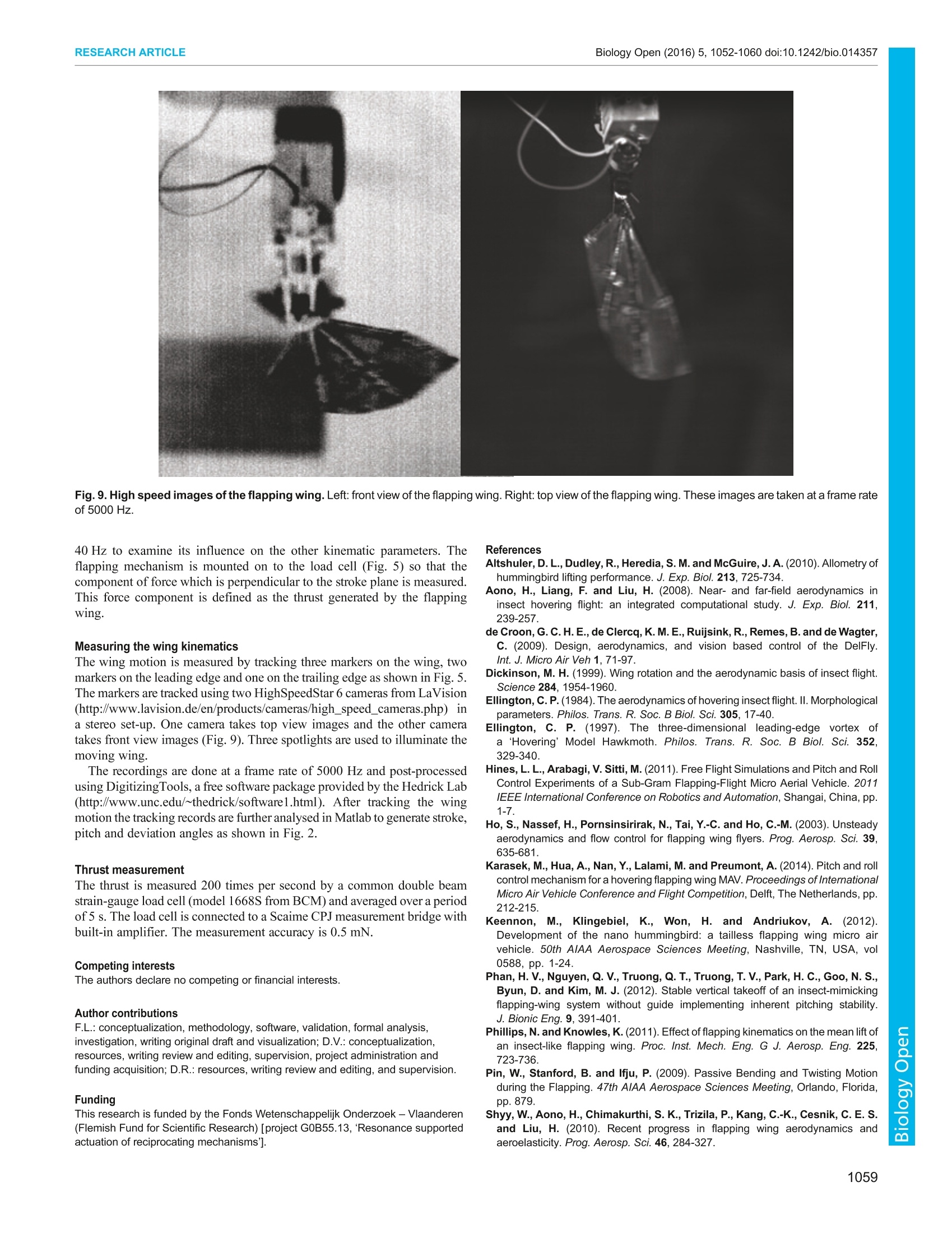
采用两台LaVision公司的HighSpeedStar6 型高速相机,记录仿真蜂鸟扑翼机的振翅动作过程。
方案详情

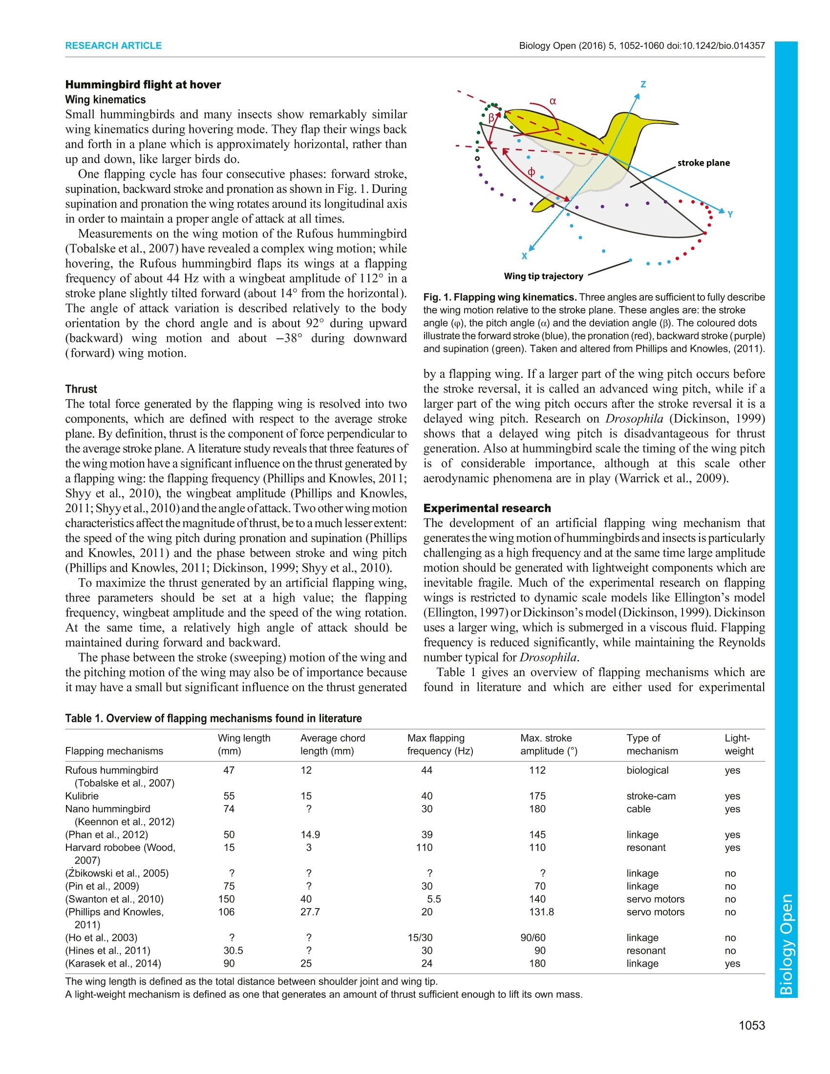
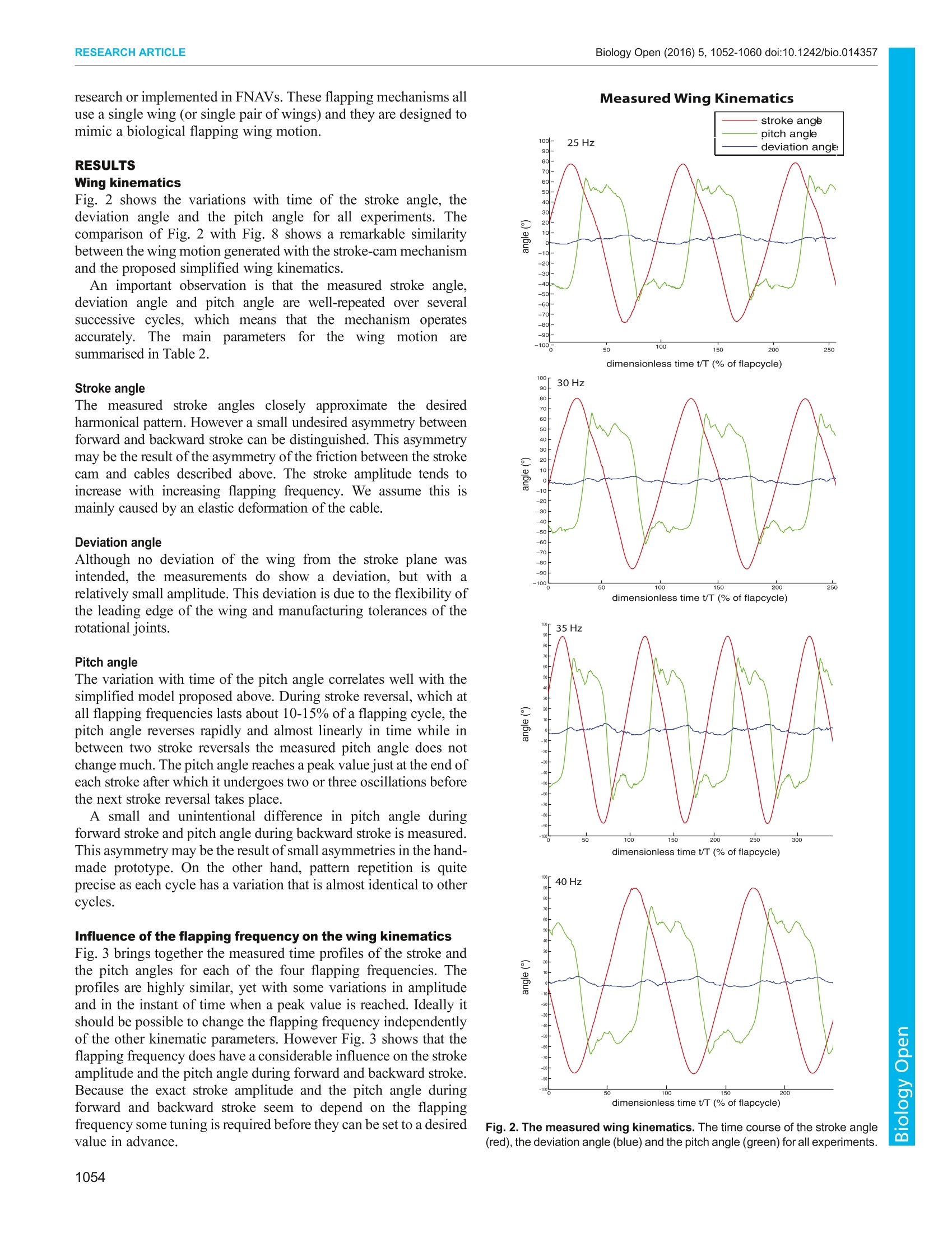
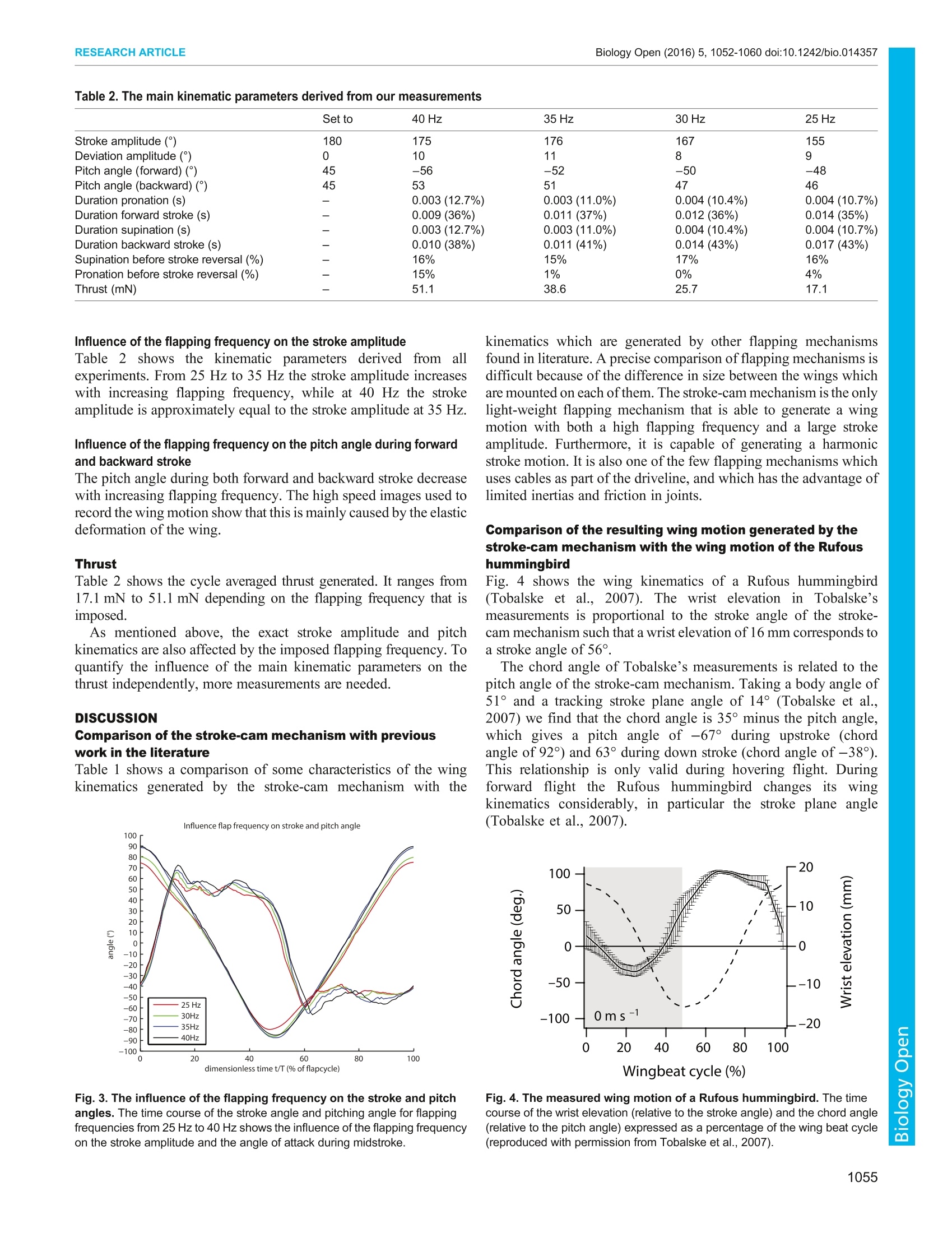
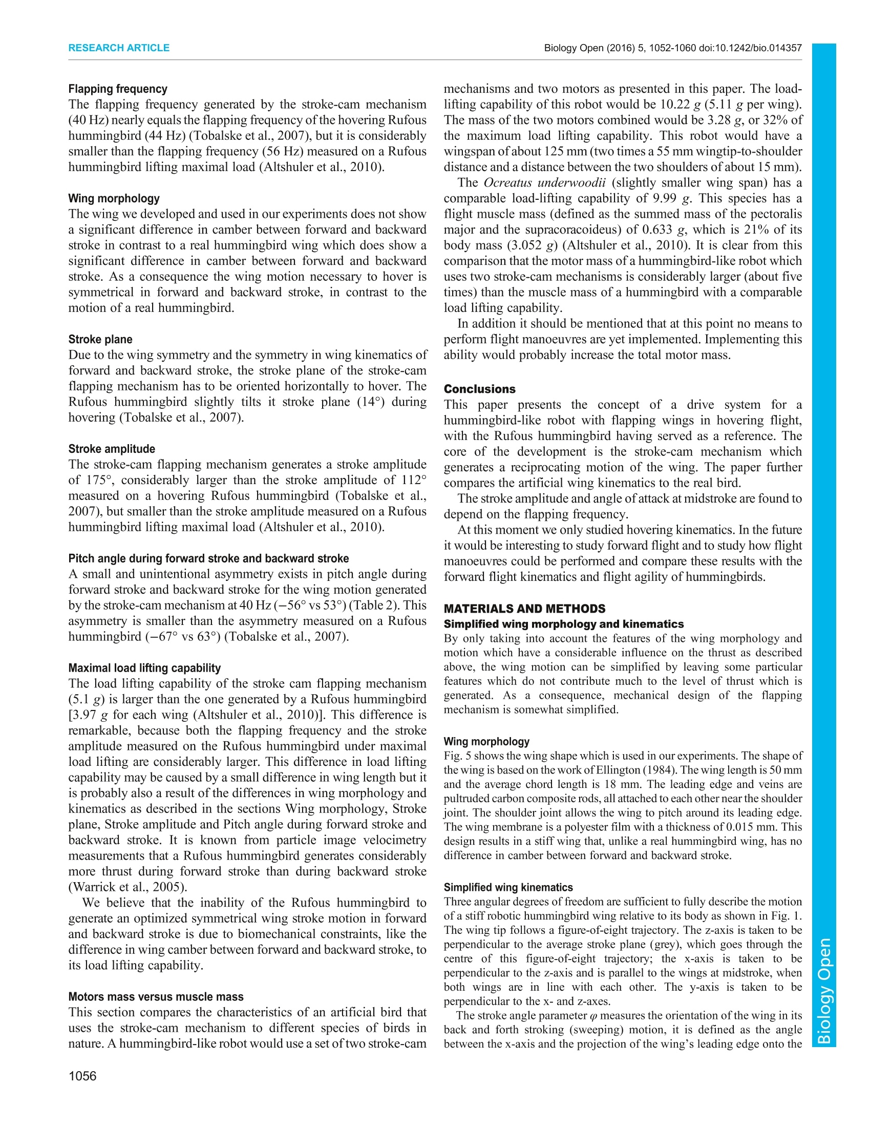
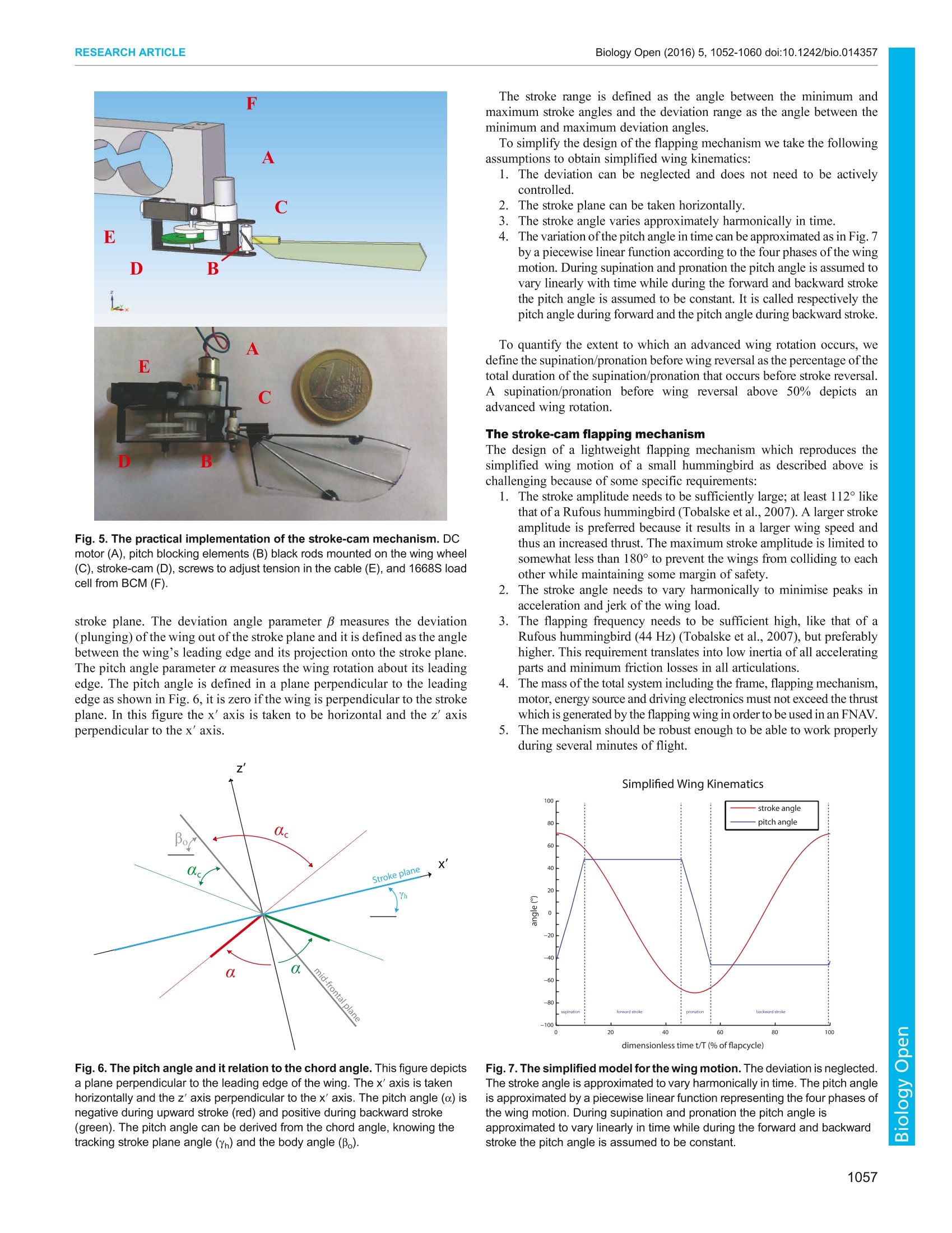
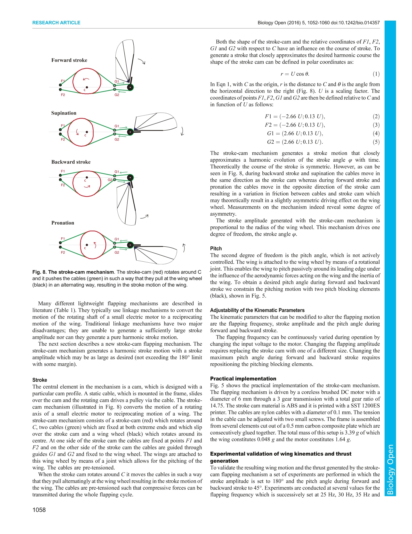
The CompanyofBiologists 2016. Published by The Company of Biologists Ltd Biology Open (2016) 5, 1052-1060 doi:10.1242/bio.014357RESEARCH ARTICLE Biology Open (2016)5,1052-1060 doi:10.1242/bio.014357RESEARCH ARTICLE Outperforming hummingbirds'load-lifting capability with alightweight hummingbird-like flapping-wing mechanism Frederik Leys*, Dominiek Reynaerts and Dirk Vandepitte The stroke-cam flapping mechanism presented in this paper closelymimics the wing motion of a hovering Rufous hummingbird. It is theonly lightweight hummingbird-sized flapping mechanism whichgenerates a harmonic wing stroke with both a high flappingfrequency and a large stroke amplitude. Experiments onalightweight prototype of this stroke-cam mechanism on a 50 mm-long wing demonstrate that a harmonic stroke motion is generatedwith a peak-to-peak stroke amplitude of 175° at a flapping frequencyof 40 Hz. It generated a mass lifting capability of 5.1 g, which is largelysufficient to lift the prototype’s mass of 3.39 g and larger than themass-lifting capability of a Rufous hummingbird. The motor mass of ahummingbird-like robot which drives the stroke-cam mechanism isconsiderably larger (about five times) than the muscle mass of ahummingbird with comparable load-lifting capability. This paperpresents a flapping wing nano aerial vehicle which is designed topossess the same lift- and thrust-generating principles of the Rufoushummingbird. The application is indoor flight. We give an overview ofthe wing kinematics and some specifications which should be met todevelop an artificial wing, and also describe the applications of thesein the mechanism which has been developed in this work. KEY WORDS: Rufous hummingbird, Trochilidae, Flapping, Wing,Mechanism, Stroke-cam, Lightweight INTRODUCTION Indoor NAVs: agility, size and payload Recent innovations in microelectronics, material science andmechanical miniaturization such as small MEMS accelerometersand gyroscopes, LiPo batteries and efficient micro-mechanicalmotors, have made it possible to develop flight vehicles at the so-called nano-scale; nano air vehicles or NAVs with a wingspan smallenough to fly indoors. These NAVs can be used for indoor missions such rescue,surveillance, security, inspection of calamities in contaminatedspaces or any other first responder applications. NAVs designed for indoor use face certain design constraintsconcerning size, weight and agility. The size is restricted by thelimited space available indoors. Regardless of the design conceptand the driving mechanism of the NAV and weight optimisation ofits components, the wingspan of any flight vehicle always sets a ( Department of Mechanical E n gineering, Katholieke U n iversiteit Leuven,Celestijnenlaan 300, Box 2420, Leuven 3 001, B elgium. ) ( *Author for correspondence (Frederik.Leys@kuleuven.be) ) F.L., 0000-0002-3461-0734 ( Thi s is an Open Access arti c l e distributed u n d er th e terms of the Creative Comm o ns AttributionLicense (http: / /crea t ivecommons.org/li c enses/by / 3.0),wh i ch permits u nre s tricted use , d istribution and reproduc t io n in any medium provided that the original w ork is p r operly at t ributed. ) ( Received 31 August 2015; Accepted 16 June 2016 ) natural limit to the maximum airborne weight ofthe NAV. Finallythe NAV should have sufficient agility to avoid all kinds ofobstaclesand fly swiftly through corridors, rooms and windows. Flapping wings In general, three types of NAVs can be distinguished: fixed wingNAVs, rotary wing NAVs, like helicopters or multi-copters, andflapping wing NAVs (or FNAVs), which flap their wings in order tofly just like hummingbirds and insects do. With the particularconstraints of indoor flight, fixedwing NAV are usuallyinappropriate as their agility iss very limited and more inparticular, they are unable to hover. Both rotary and flappingwing NAVs offer viable alternatives. While rotary wing NAVs arewell established, the Nano Hummingbird (Keennon et al., 2012) isstill the only controllable flapping wing NAV able to fly untethered,next to some clapping wing NAVs like the Delfly micro (de Croonet al., 2009; http://www.delfly.nl/micro.html). Small hummingbirds are able to perform all kinds of remarkableflying manoeuvres. They can fly forwards, backwards, sideways,hover and they can even transition swiftly between these flightregimes. They are the living proof that flapping wing propulsion is apromising choice for agile artificial NAVs. Severaaauthorsshaveinvestigateddttlhe mechanisms andaerodynamic phenomena with small birds and insects in differentflight regimes. Dickinson (1999), Ellington (1994), Aono et al.(2008) and Warrick et al.(2009) distinguish four thrust-enhancingaerodynamic phenomena that are responsible for the exceptionallyhigh thrust generated by small flapping wings; leading edge vortexstabilization, advanced wing rotation, wake capture and added masseffect. However, a specific and complex wing motion is required tobe able to take advantage of these lift-enhancing phenomena. The complexity required to artificially generate the wing motionof hummingbirds has limited the successful development ofoperational FNAVs up to now to a single development (Keennonet al., 2012). Rufous hummingbird The proposed wing-flapping mechanism generates a wing motionwhich is based on the wing motion of the Rufous hummingbird(Selasphorus rufus). The Rufous hummingbird is the only smallhummingbird species of which the wing motion is alreadythoroughly studied (Tobalske et al., 2007). In addition, the wingsof this bird are small enough and they flap fast enough to takeadvantage of at least some of the low Reynolds number lift-enhancing aerodynamic phenomena which are described above andwhich larger species do not take advantage of. Despite the smallsize of its wings, the mass of the Rufous hummingbird is about3.4g. This mass is relatively high compared with otherhummingbirds, which enables the development of a bio-inspiredFNAV based on a design spec for the total mass in the same order ofmagnitude as the Rufous hummingbird. Hummingbird flight at hover Wing kinematics Small hummingbirds and many insects show remarkably similarwing kinematics during hovering mode. They flap their wings backand forth in a plane which is approximately horizontal, rather thanup and down, like larger birds do. One flapping cycle has four consecutive phases: forward stroke,supination, backward stroke and pronation as shown in Fig. 1. Duringsupination and pronation the wing rotates around its longitudinal axisin order to maintain a proper angle of attack at all times. Measurements on the wing motion of the Rufous hummingbird(Tobalske et al., 2007) have revealed a complex wing motion; whilehovering, the Rufous hummingbird flaps its wings at a flappingfrequency of about 44 Hz with a wingbeat amplitude of 112° in astroke plane slightly tilted forward (about 14°from the horizontal).The angle of attack variation is described relatively to the bodyorientation by the chord angle and is about 92° during upward(backward) wing motion and about -38°cduring downward(forward) wing motion. Thrust The total force generated by the flapping wing is resolved into twocomponents, which are defined with respect to the average strokeplane. By definition, thrust is the component of force perpendicular tothe average stroke plane. A literature study reveals that three features ofthe wing motion have a significant influence on the thrust generated bya flapping wing: the flapping frequency (Phillips and Knowles, 2011;Shyy et al., 2010), the wingbeat amplitude (Phillips and Knowles,2011; Shyyetal.,2010) and the angle ofattack. Two other wing motioncharacteristics affect the magnitude ofthrust, be to a much lesser extent:the speed of the wing pitch during pronation and supination (Phillipsand Knowles, 2011) and the phase between stroke and wing pitch(Phillips and Knowles, 2011; Dickinson, 1999; Shyy et al., 2010). To maximize the thrust generated by an artificial flapping wing,three parameters should be set at a high value; the flappingfrequency, wingbeat amplitude and the speed of the wing rotation.At the same time, a relatively high angle of attack should bemaintained during forward and backward. The phase between the stroke (sweeping) motion of the wing andthe pitching motion of the wing may also be of importance becauseit may have a small but significant influence on the thrust generated Fig. 1. Flapping wing kinematics. Three angles are sufficient to fully describethe wing motion relative to the stroke plane. These angles are: the strokeangle ((), the pitch angle (a) and the deviation angle (B). The coloured dotsillustrate the forward stroke (blue), the pronation (red), backward stroke (purple)and supination (green). Taken and altered from Phillips and Knowles, (2011). by a flapping wing. If a larger part of the wing pitch occurs beforethe stroke reversal, it is called an advanced wing pitch, while if alarger part of the wing pitch occurs after the stroke reversal it is adelayed wing pitch. Research on Drosophila (Dickinson, 1999)shows that a delayed wing pitch is disadvantageous for thrustgeneration. Also at hummingbird scale the timing of the wing pitchis of considerable importance, although at this scale otheraerodynamic phenomena are in play (Warrick et al., 2009). Experimental research The development of an artificial flapping wing mechanism thatgenerates the wing motion of hummingbirds and insects is particularlychallenging as a high frequency and at the same time large amplitudemotion should be generated with lightweight components which areinevitable fragile. Much of the experimental research on flappingwings is restricted to dynamic scale models like Ellington’s model(Ellington, 1997) or Dickinson’s model (Dickinson, 1999). Dickinsonuses a larger wing, which is submerged in a viscous fluid. Flappingfrequency is reduced significantly, while maintaining the Reynoldsnumber typical for Drosophila. Table 1 gives an overview of flapping mechanisms which arefound in literature and which are either used for experimental Table 1. Overview of flapping mechanisms found in literature Wing length Average chord Max flapping Max. stroke lype of Light- Flapping mechanisms (mm) length (mm) frequency (Hz) amplitude (°) mechanism weight Rufous hummingbird 47 12 44 112 biological yes (Tobalske et al.,2007) Kulibrie 38 175 stroke-cam yes Nano hummingbird 180 cable yes (Keennon et al., 2012) (Phan et al., 2012) 14.9 39 145 linkage yes Harvard robobee (Wood, 3 110 110 resonant yes 2007) (Zbikowski et al.,2005) ? ? ? linkage (Pin et al.,2009) 75 30 70 linkage (Swanton et al., 2010) 150 5.5 140 servo motors (Phillips and Knowles, 106 27.7 20 131.8 servo motors 2011) (Ho et al., 2003) ? 15/30 90/60 linkage (Hines et al., 2011) 30.5 90 resonant (Karasek et al., 2014) 90 180 linkage yes The wing length is defined as the total distance between shoulder joint and wing tip. A light-weight mechanism is defined as one that generates an amount of thrust sufficient enough to lift its own mass. research or implemented in FNAVs. These flapping mechanisms alluse a single wing (or single pair of wings) and they are designed tomimic a biological flapping wing motion. RESULTS Wing kinematics Fig. 2 shows the variations with time of the stroke angle, thedeviation angle and the pitch angle for all experiments. Thecomparison of Fig. 2 with Fig. 8 shows a remarkable similaritybetween the wing motion generated with the stroke-cam mechanismand the proposed simplified wing kinematics. An important observation is that the measured stroke angle,deviation angle and pitch angle are well-repeated over severalsuccessive cycles, which means that the mechanism operatesaccurately. The mainparameters ffor thewing motion aresummarised in Table 2. Stroke angle The measured stroke angles closely approximate the desiredharmonical pattern. However a small undesired asymmetry betweenforward and backward stroke can be distinguished. This asymmetrymay be the result of the asymmetry ofthe friction between the strokecam and cables described above. The stroke amplitude tends toincrease with increasing flapping frequency. We assume this ismainly caused by an elastic deformation of the cable. Deviation angle Although no deviation of the wing from the stroke plane wasintended, the measurements do show a deviation, but with arelatively small amplitude. This deviation is due to the flexibility ofthe leading edge of the wing and manufacturing tolerances of therotational joints. Pitch angle The variation with time of the pitch angle correlates well with thesimplified model proposed above. During stroke reversal, which atall flapping frequencies lasts about 10-15% of a flapping cycle, thepitch angle reverses rapidly and almost linearly in time while inbetween two stroke reversals the measured pitch angle does notchange much. The pitch angle reaches a peak value just at the end ofeach stroke after which it undergoes two or three oscillations beforethe next stroke reversal takes place. A small and unintentional difference in pitch angle duringforward stroke and pitch angle during backward stroke is measured.This asymmetry may be the result of small asymmetries in the hand-made prototype. On the other hand, pattern repetition is quiteprecise as each cycle has a variation that is almost identical to othercycles. Influence of the flapping frequency on the wing kinematics Fig. 3 brings together the measured time profiles of the stroke andthe pitch angles for each of the four flapping frequencies. Theprofiles are highly similar, yet with some variations in amplitudeand in the instant of time when a peak value is reached. Ideally itshould be possible to change the flapping frequency independentlyof the other kinematic parameters. However Fig. 3 shows that theflapping frequency does have a considerable influence on the strokeamplitude and the pitch angle during forward and backward stroke.Because the exact stroke amplitude and the pitch angle duringforward and backward stroke seem to depend on the flappingfrequency some tuning is required before they can be set to a desiredvalue in advance. Measured Wing Kinematics dimensionless time t/T (% of flapcycle) Set to 40 Hz 35 Hz 30 Hz 25 Hz Stroke amplitude(°) 180 175 176 167 155 Deviation amplitude (°) 0 10 11 8 9 Pitch angle (forward) (°) 45 -56 -52 -50 -48 Pitch angle (backward) (°) 45 53 51 47 46 Duration pronation (s) 0.003(12.7%) 0.003(11.0%) 0.004(10.4%) 0.004(10.7%) Duration forward stroke (s) 0.009 (36%) 0.011(37%) 0.012(36%) 0.014 (35%) Duration supination (s) - 0.003(12.7%) 0.003(11.0%) 0.004(10.4%) 0.004(10.7%) Duration backward stroke (s) - 0.010(38%) 0.011 (41%) 0.014(43%) 0.017 (43%) Supination before stroke reversal (%) - 16% 15% 17% 16% Pronation before stroke reversal (%) 一 15% 1% 0% 4% Thrust (mN) 51.1 38.6 25.7 17.1 Influence of the flapping frequency on the stroke amplitude Tablee 2 shows the kinematic parameters derived from allexperiments. From 25 Hz to 35 Hz the stroke amplitude increaseswith increasing flapping frequency, while at 40 Hz the strokeamplitude is approximately equal to the stroke amplitude at 35 Hz. Influence of the flapping frequency on the pitch angle during forwardand backward stroke The pitch angle during both forward and backward stroke decreasewith increasing flapping frequency. The high speed images used torecord the wing motion show that this is mainly caused by the elasticdeformation of the wing. Thrust Table 2 shows the cycle averaged thrust generated. It ranges from17.1 mN to 51.1 mN depending on the flapping frequency that isimposed. As mentioned above, the exact stroke amplitude and pitchkinematics are also affected by the imposed flapping frequency.Toquantify the influence of the main kinematic parameters on thethrust independently, more measurements are needed. DISCUSSIONComparison of the stroke-cam mechanism with previous work in the literature Table 1 shows a comparison of some characteristics of the wingkinematics generated by the stroke-cam mechanism with the Fig. 3. The influence of the flapping frequency on the stroke and pitchangles. The time course of the stroke angle and pitching angle for flappingfrequencies from 25 Hz to 40 Hz shows the influence of the flapping frequencyon the stroke amplitude and the angle of attack during midstroke. kinematics which are generated by other flapping mechanismsfound in literature. A precise comparison of flapping mechanisms isdifficult because of the difference in size between the wings whichare mounted on each of them. The stroke-cam mechanism is the onlylight-weight flapping mechanism that is able to generate a wingmotion with both a high flapping frequency and a large strokeamplitude. Furthermore, it is capable of generating a harmonicstroke motion. It is also one of the few flapping mechanisms whichuses cables as part of the driveline, and which has the advantage oflimited inertias and friction in joints. Comparison of the resulting wing motion generated by thestroke-cam mechanism with the wing motion of the Rufoushummingbird Fig. 4 shows the wing kinematics of a Rufous hummingbird(Tobalske et al., 2007). The wrist elevation in Tobalske’smeasurements is proportional to the stroke angle of the stroke-cam mechanism such that a wrist elevation of 16 mm corresponds toa stroke angle of 56°. The chord angle of Tobalske’s measurements is related to thepitch angle of the stroke-cam mechanism. Taking a body angle of51°and a tracking stroke plane angle of 14°(Tobalske et al.,2007) we find that the chord angle is 35° minus the pitch angle,which gives a pitch angle of -67° during upstroke (chordangle of 92°) and 63° during down stroke (chord angle of -38°).This relationship is only valid during hovering flight. Duringforward flight the Rufous hummingbird changes its wingkinematics considerably, in particular the stroke plane angle(Tobalske et al., 2007). Fig. 4. The measured wing motion of a Rufous hummingbird. The timecourse of the wrist elevation (relative to the stroke angle) and the chord angle(relative to the pitch angle) expressed as a percentage of the wing beat cycle(reproduced with permission from Tobalske et al., 2007). The flapping frequency generated by the stroke-cam mechanism(40 Hz) nearly equals the flapping frequency of the hovering Rufoushummingbird (44Hz) (Tobalske et al., 2007), but it is considerablysmaller than the flapping frequency (56 Hz) measured on a Rufoushummingbird lifting maximal load (Altshuler et al., 2010). Wing morphology The wing we developed and used in our experiments does not showa significant difference in camber between forward and backwardstroke in contrast to a real hummingbird wing which does show asignificant difference in camber between forward and backwardstroke. As a consequence the wing motion necessary to hover issymmetrical in forward and backward stroke, in contrast to themotion of a real hummingbird. Stroke plane Due to the wing symmetry and the symmetry in wing kinematics offorward and backward stroke, the stroke plane of the stroke-camflapping mechanism has to be oriented horizontally to hover. TheRufous hummingbird slightly tilts it stroke plane (14°) duringhovering (Tobalske et al., 2007). Stroke amplitude The stroke-cam flapping mechanism generates a stroke amplitudeof 175°, considerably larger than the stroke amplitude of 112°measured on a hovering Rufous hummingbird (Tobalske et al.,2007), but smaller than the stroke amplitude measured on a Rufoushummingbird lifting maximal load (Altshuler et al., 2010). Pitch angle during forward stroke and backward stroke A small and unintentional asymmetry exists in pitch angle duringforward stroke and backward stroke for the wing motion generatedby the stroke-cam mechanism at 40 Hz (-56° vs 53°)(Table 2). Thisasymmetry is smaller than the asymmetry measured on a Rufoushummingbird (-67°vs 63°) (Tobalske et al., 2007). Maximal load lifting capability The load lifting capability of the stroke cam flapping mechanism(5.1 g) is larger than the one generated by a Rufous hummingbird[3.97 g for each wing (Altshuler et al., 2010)]. This difference isremarkable, because both the flapping frequency and the strokeamplitude measured on the Rufous hummingbird under maximalload lifting are considerably larger. This difference in load liftingcapability may be caused by a small difference in wing length but itis probably also a result of the differences in wing morphology andkinematics as described in the sections Wing morphology, Strokeplane, Stroke amplitude and Pitch angle during forward stroke andbackward stroke. It is known from particle image velocimetrymeasurements that a Rufous hummingbird generates considerablymore thrust during forward stroke than during backward stroke(Warrick et al.,2005). We believe that the inability of the Rufous hummingbird togenerate an optimized symmetrical wing stroke motion in forwardand backward stroke is due to biomechanical constraints, like thedifference in wing camber between forward and backward stroke, toits load lifting capability. Motors mass versus muscle mass This section compares the characteristics of an artificial bird thatuses the stroke-cam mechanism to different species of birds innature. A hummingbird-like robot would use a set oftwo stroke-cam mechanisms and two motors as presented in this paper. The load-lifting capability of this robot would be 10.22 g (5.11 g per wing).The mass of the two motors combined would be 3.28 g, or 32% ofthe maximum load lifting capability. This robot would have awingspan of about 125 mm (two times a 55 mm wingtip-to-shoulderdistance and a distance between the two shoulders of about 15 mm). The Ocreatus underwoodii (slightly smaller wing span) has acomparable load-lifting capability of 9.99 g. This species has aflight muscle mass (defined as the summed mass of the pectoralismajor and the supracoracoideus) of 0.633 g, which is 21% of itsbody mass (3.052 g) (Altshuler et al., 2010). It is clear from thiscomparison that the motor mass of a hummingbird-like robot whichuses two stroke-cam mechanisms is considerably larger (about fivetimes) than the muscle mass of a hummingbird with a comparableload lifting capability. In addition it should be mentioned that at this point no means toperform flight manoeuvres are yet implemented. Implementing thisability would probably increase the total motor mass. Conclusions This paper presents the concept of a drive system for ahummingbird-like robot with flapping wings in hovering flight,with the Rufous hummingbird having served as a reference. Thecore of the development is the stroke-cam mechanism whichgenerates a reciprocating motion of the wing. The paper furthercompares the artificial wing kinematics to the real bird. The stroke amplitude and angle of attack at midstroke are found todepend on the flapping frequency. At this moment we only studied hovering kinematics. In the futureit would be interesting to study forward flight and to study how flightmanoeuvres could be performed and compare these results with theforward flight kinematics and flight agility of hummingbirds. MATERIALS AND METHODS Simplified wing morphology and kinematics By only taking into account the features of the wing morphology andmotion which have a considerable influence on the thrust as describedabove, the wing motion can be simplified by leaving some particularfeatures which do not contribute much to the level of thrust which isgenerated. As a consequence, mechanical design of the flappingmechanism is somewhat simplified. Wing morphology Fig. 5 shows the wing shape which is used in our experiments. The shape ofthe wing is based on the work ofEllington (1984). The wing length is 50 mmand the average chord length is 18 mm. The leading edge and veins arepultruded carbon composite rods, all attached to each other near the shoulderjoint. The shoulder joint allows the wing to pitch around its leading edge.The wing membrane is a polyester film with a thickness of 0.015 mm. Thisdesign results in a stiff wing that, unlike a real hummingbird wing, has nodifference in camber between forward and backward stroke. Simplified wing kinematics Three angular degrees of freedom are sufficient to fully describe the motionof a stiff robotic hummingbird wing relative to its body as shown in Fig. 1.The wing tip follows a figure-of-eight trajectory. The z-axis is taken to beperpendicular to the average stroke plane (grey), which goes through thecentre of this figure-of-eight trajectory; the x-axisis taken to beperpendicular to the z-axis and is parallel to the wings at midstroke, whenboth wings are in line with each other. The y-axis is taken to beperpendicular to the x- and z-axes. The stroke angle parameter o measures the orientation ofthe wing in itsback and forth stroking (sweeping) motion, it is defined as the anglebetween the x-axis and the projection of the wing’s leading edge onto the Fig. 5. The practical implementation of the stroke-cam mechanism. DCmotor (A), pitch blocking elements (B) black rods mounted on the wing wheel(C), stroke-cam (D), screws to adjust tension in the cable (E), and 1668S loadcell from BCM (F). stroke plane. The deviation angle parameter B measures the deviation(plunging) of the wing out of the stroke plane and it is defined as the anglebetween the wing’s leading edge and its projection onto the stroke plane.The pitch angle parameter a measures the wing rotation about its leadingedge. The pitch angle is defined in a plane perpendicular to the leadingedge as shown in Fig. 6, it is zero if the wing is perpendicular to the strokeplane. In this figure the x’axis is taken to be horizontal and the z' axisperpendicular to the x'axis. The stroke range is defined as the angle between the minimum andmaximum stroke angles and the deviation range as the angle between theminimum and maximum deviation angles. To simplify the design of the flapping mechanism we take the followingassumptions to obtain simplified wing kinematics: 1. The deviation can be neglected and does not need to be activelycontrolled. 2The stroke plane can be taken horizontally.34 The stroke angle varies approximately harmonically in time. The variation of the pitch angle in time can be approximated as in Fig. 7by a piecewise linear function according to the four phases of the wingmotion. During supination and pronation the pitch angle is assumed tovary linearly with time while during the forward and backward strokethe pitch angle is assumed to be constant. It is called respectively thepitch angle during forward and the pitch angle during backward stroke. To quantify the extent to which an advanced wing rotation occurs, wedefine the supination/pronation before wing reversal as the percentage of thetotal duration of the supination/pronation that occurs before stroke reversal.A supination/pronation before wing reversal above 50% depicts anadvanced wing rotation. The stroke-cam flapping mechanism The design of a lightweight flapping mechanism which reproduces thesimplified wing motion of a small hummingbird as described above ischallenging because of some specific requirements: 1. The stroke amplitude needs to be sufficiently large; at least 112°likethat of a Rufous hummingbird (Tobalske et al.,2007). A larger strokeamplitude is preferred because it results in a larger wing speed andthus an increased thrust. The maximum stroke amplitude is limited tosomewhat less than 180° to prevent the wings from colliding to eachother while maintaining some margin of safety. 2..TThe stroke angle needs to vary harmonically to minimise peaks inacceleration and jerk of the wing load. 3..TThe flapping frequency needs to be sufficient high, like that of aRufous hummingbird (44 Hz) (Tobalske et al., 2007), but preferablyhigher. This requirement translates into low inertia of all acceleratingparts and minimum friction losses in all articulations. 4.The mass of the total system including the frame, flapping mechanism,motor, energy source and driving electronics must not exceed the thrustwhich is generated by the flapping wing in order to be used in an FNAV. 5.The mechanism should be robust enough to be able to work properlyduring several minutes of flight. Supination Fig.8. The stroke-cam mechanism. The stroke-cam (red) rotates around Cand it pushes the cables (green) in such a way that they pull at the wing wheel(black) in an alternating way, resulting in the stroke motion of the wing. Many different lightweight flapping mechanisms are described inliterature (Table 1). They typically use linkage mechanisms to convert themotion of the rotating shaft of a small electric motor to a reciprocatingmotion of the wing. Traditional linkage mechanisms have two majordisadvantages; they are unable to generate a sufficiently large strokeamplitude nor can they generate a pure harmonic stroke motion. The next section describes a new stroke-cam flapping mechanism. Thestroke-cam mechanism generates a harmonic stroke motion with a strokeamplitude which may be as large as desired (not exceeding the 180° limitwith some margin). Stroke The central element in the mechanism is a cam, which is designed with aparticular cam profile. A static cable, which is mounted in the frame, slidesover the cam and the rotating cam drives a pulley via the cable. The stroke-cam mechanism (illustrated in Fig. 8) converts the motion of a rotatingaxis of a small electric motor to reciprocating motion of a wing. Thestroke-cam mechanism consists of a stroke-cam (red) which rotates aroundC, two cables (green) which are fixed at both extreme ends and which slipover the stroke cam and a wing wheel (black) which rotates around itscentre. At one side of the stroke cam the cables are fixed at points Fl andF2 and on the other side of the stroke cam the cables are guided throughguides GI and G2 and fixed to the wing wheel. The wings are attached tothis wing wheel by means of a joint which allows for the pitching of thewing. The cables are pre-tensioned. When the stroke cam rotates around C it moves the cables in such a waythat they pull alternatingly at the wing wheel resulting in the stroke motion ofthe wing. The cables are pre-tensioned such that compressive forces can betransmitted during the whole flapping cycle. Both the shape of the stroke-cam and the relative coordinates of F1, F2,G1 and G2 with respect to C have an influence on the course of stroke. Togenerate a stroke that closely approximates the desired harmonic course theshape of the stroke cam can be defined in polar coordinates as: In Eqn 1, with C as the origin, r is the distance to C and O is the angle fromthe horizontal direction to the right (Fig. 8). U is a scaling factor. Thecoordinates of points F1,F2, Gl and G2 are then be defined relative to Candin function of U as follows: F1=(-2.66 U;0.13 U),F2=(-2.66 U;0.13 U), G1=(2.66 U;0.13 U), G2=(2.66 U;0.13 U). 日 The stroke-cam mechanism generates a stroke motion that closelyapproximates a harmonic evolution of the stroke angle o with time.Theoretically the course of the stroke is symmetric. However, as can beseen in Fig. 8, during backward stroke and supination the cables move inthe same direction as the stroke cam whereas during forward stroke andpronation the cables move in the opposite direction of the stroke camresulting in a variation in friction between cables and stroke cam whichmay theoretically result in a slightly asymmetric driving effect on the wingwheel. Measurements on the mechanism indeed reveal some degree ofasymmetry. The stroke amplitude generated with the stroke-cam mechanism isproportional to the radius of the wing wheel. This mechanism drives onedegree of freedom, the stroke angle p. Pitch The second degree of freedom is the pitch angle, which is not activelycontrolled. The wing is attached to the wing wheel by means of a rotationaljoint. This enables the wing to pitch passively around its leading edge underthe influence of the aerodynamic forces acting on the wing and the inertia ofthe wing. To obtain a desired pitch angle during forward and backwardstroke we constrain the pitching motion with two pitch blocking elements(black), shown in Fig. 5. Adjustability of the Kinematic Parameters The kinematic parameters that can be modified to alter the flapping motionare the flapping frequency, stroke amplitude and the pitch angle duringforward and backward stroke. The flapping frequency can be continuously varied during operation bychanging the input voltage to the motor. Changing the flapping amplituderequires replacing the stroke cam with one of a different size. Changing themaximum pitch angle during forward and backward stroke requiresrepositioning the pitching blocking elements. Practical implementation Fig. 5 shows the practical implementation of the stroke-cam mechanism.The flapping mechanism is driven by a coreless brushed DC motor with adiameter of 6 mm through a 3 gear transmission with a total gear ratio of14.75. The stroke cam material is ABS and it is printed with a SST 1200ESprinter. The cables are nylon cables with a diameter of 0.1 mm. The tensionin the cable can be adjusted with two small screws. The frame is assembledfrom several elements cut out of a 0.5 mm carbon composite plate which areconsecutively glued together. The total mass of this setup is 3.39 g of whichthe wing constitutes 0.048 g and the motor constitutes 1.64 g. Experimental validation of wing kinematics and thrustgeneration To validate the resulting wing motion and the thrust generated by the stroke-cam flapping mechanism a set of experiments are performed in which thestroke amplitude is set to 180° and the pitch angle during forward andbackward stroke to 45°. Experiments are conducted at several values for theflapping frequency which is successively set at 25 Hz, 30 Hz, 35 Hz and Fig. 9. High speed images of the flapping wing. Left: front view of the flapping wing. Right: top view of the flapping wing. These images are taken at a frame rateof 5000 Hz. 40 Hz to examine its influence on the other kinematic parameters. Theflapping mechanism is mounted on to the load cell (Fig. 5) so that thecomponent of force which is perpendicular to the stroke plane is measured.This force component is defined as the thrust generated by the flappingwing. Measuring the wing kinematics The wing motion is measured by tracking three markers on the wing, twomarkers on the leading edge and one on the trailing edge as shown in Fig. 5.The markers are tracked using two HighSpeedStar 6 cameras from LaVision(http://www.lavision.de/en/products/cameras/high_speed_cameras.php) ina stereo set-up. One camera takes top view images and the other cameratakes front view images (Fig. 9). Three spotlights are used to illuminate themoving wing. The recordings are done at a frame rate of 5000 Hz and post-processedusing DigitizingTools, a free software package provided by the Hedrick Lab(http://www.unc.edu/~thedrick/software1.html). After tracking the wingmotion the tracking records are further analysed in Matlab to generate stroke,pitch and deviation angles as shown in Fig. 2. Thrust measurement The thrust is measured 200 times per second by a common double beamstrain-gauge load cell (model 1668S from BCM) and averaged over a periodof 5 s. The load cell is connected to a Scaime CPJ measurement bridge withbuilt-in amplifier. The measurement accuracy is 0.5 mN. Competing interests The authors declare no competing or financial interests. Author contributions F.L.: conceptualization, methodology, software, validation, formal analysis,investigation, writing original draft and visualization; D.V.: conceptualization,resources, writing review and editing, supervision, project administration andfunding acquisition; D.R.: resources, writing review and editing, and supervision. Funding This research is funded by the Fonds Wetenschappelijk Onderzoek-Vlaanderen(Flemish Fund for Scientific Research) [project G0B55.13, ‘Resonance supportedactuation of reciprocating mechanisms]. ( References ) Altshuler,D. L.,Dudley, R., Heredia, S. M.and McGuire,J. A. (2010). Allometry ofhummingbird lifting performance. J. Exp. Biol. 213, 725-734. Aono, H., Liang, F. and Liu, H. (2008). Near- and far-field aerodynamics ininsect hovering flight: an integrated computational study. J. Exp. Biol. 211,239-257. de Croon,G. C. H.E., de Clercq, K. M. E.,Ruijsink,R., Remes, B. and de Wagter,C. (2009). Design, aerodynamics, and vision based control of the DelFly.Int. J. Micro Air Veh 1, 71-97. DickinsonM. H.(1999). Wing rotation and the aerodynamic basis of insect flight.Science 284. 1954-1960. Ellington, C. P. (1984). The aerodynamics of hovering insect flight. ⅡI. Morphologicalparameters. Philos. Trans. R. Soc. B Biol. Sci. 305, 17-40. Ellington, C. P. (1997). The three-dimensional leading-edge vortex ofa ‘Hovering’Model Hawkmoth. Philos. Trans. R. Soc. B Biol. Sci. 352,329-340. Hines,L. L., Arabagi, V. Sitti,M. (2011).Free Flight Simulations and Pitch and RollControl Experiments of a Sub-Gram Flapping-Flight Micro Aerial Vehicle. 2011IEEE International Conference on Robotics and Automation, Shangai, China, pp.1-7. Ho, S., Nassef, H., Pornsinsirirak, N., Tai, Y.-C. and Ho, C.-M.(2003). Unsteadyaerodynamics and flow control for flapping wing flyers. Prog. Aerosp. Sci. 39,635-681. Karasek, M., Hua,A., Nan, Y., Lalami, M. and Preumont, A. (2014). Pitch and rollcontrol mechanism for a hovering flapping wing MAV. Proceedings of InternationalMicro Air Vehicle Conference and Flight Competition, Delft, The Netherlands, pp.212-215. Keennon, M., Klingebiel, K., Won, H. aand Andriukov, A. (2012).Development of the nano hummingbird: a tailless flapping wing micro airvehicle. 50th AIAA Aerospace Sciences Meeting, Nashville, TN,USA, vol0588, pp. 1-24. Phan, H. V.,Nguyen, Q. V., Truong, Q. T., Truong, T. V., Park, H. C., Goo, N. S.,Byun, D. and Kim, M. J. (2012). Stable vertical takeoff of an insect-mimickingflapping-wing system without guide implementing inherent pitching stability.J. Bionic Eng. 9, 391-401. Phillips, N. and Knowles,K.(2011). Effect of flapping kinematics on the mean lift ofan insect-like flapping wing. Proc. Inst. Mech. Eng. G J. Aerosp. Eng. 225,723-736. Pin, W., Stanford, B. and Ifju, P. (2009). Passive Bending and Twisting Motionduring the Flapping. 47th AIAA Aerospace Sciences Meeting, Orlando, Florida,pp.879. Shyy, W., Aono, H., Chimakurthi, S. K., Trizila, P., Kang, C.-K.,Cesnik, C. E. S.and Liu, H. (2010). Recent progress in flapping wing aerodynamics andaeroelasticity. Prog. Aerosp. Sci.46, 284-327. Swanton, E. W. M., Vanier, B. A. and Mohseni, K. (2010). Flow visualizationand wall shear stress of a flapping model hummingbird wing. Exp. Fluids 49,657-671. Tobalske, B. W., Warrick,D. R., Clark, C. J., Powers, D. R., Hedrick, T. L., Hyder,G. A. and Biewener,A. A. (2007). Three-dimensional kinematics of hummingbirdflight. J. Exp. Biol. 210, 2368-2382. Warrick,D. R., Tobalske, B. W. and Powers, D. R. (2005). Aerodynamics of thehovering hummingbird. Nature 435, 1094-10997. Warrick, D. R., Tobalske, B. W. and Powers, D. R. (2009). Lift Production in thehovering hummingbird. Proc. R. Soc.B Biol. Sci. 276, 3747-3752. Wood, R. J. (2007).Liftoff of a 60 mg flapping-wing MAV. Proceedings of the IEEEInternational Conference on Intelligent Robots and Systems, San Diego, CA, pp.1889-1894. ( Zbikowski, R., G alinski, c. and P edersen, C . B. (2 0 05). F o ur-bar l i nkage mechanism fo r insectlike flapping wings in hover: concept and an ou t line of its realization. J . Mech. Des. 127, 817-824. ) The stroke-cam flapping mechanism presented in this paper closelymimics the wing motion of a hovering Rufous hummingbird. It is theonly lightweight hummingbird-sized flapping mechanism whichgenerates a harmonic wing stroke with both a high flappingfrequency and a large stroke amplitude. Experiments on alightweight prototype of this stroke-cam mechanism on a 50 mmlongwing demonstrate that a harmonic stroke motion is generatedwith a peak-to-peak stroke amplitude of 175° at a flapping frequencyof 40 Hz. It generated a mass lifting capability of 5.1 g, which is largelysufficient to lift the prototype’s mass of 3.39 g and larger than themass-lifting capability of a Rufous hummingbird. The motor mass of ahummingbird-like robot which drives the stroke-cam mechanism isconsiderably larger (about five times) than the muscle mass of ahummingbird with comparable load-lifting capability. This paperpresents a flapping wing nano aerial vehicle which is designed topossess the same lift- and thrust-generating principles of the Rufoushummingbird. The application is indoor flight. We give an overview ofthe wing kinematics and some specifications which should be met todevelop an artificial wing, and also describe the applications of thesein the mechanism which has been developed in this work.
确定
还剩7页未读,是否继续阅读?

产品配置单


北京欧兰科技发展有限公司为您提供《轻量化类蜂鸟扑翼机中流场检测方案(粒子图像测速)》,该方案主要用于其他中流场检测,参考标准--,《轻量化类蜂鸟扑翼机中流场检测方案(粒子图像测速)》用到的仪器有德国LaVision PIV/PLIF粒子成像测速场仪、LaVision HighSpeedStar 高帧频相机、PLIF平面激光诱导荧光火焰燃烧检测系统
推荐专场


CCD相机/影像CCD
更多


相关方案
更多
该厂商其他方案
更多