


方案详情
文
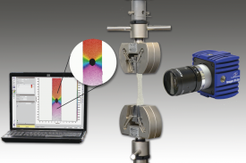
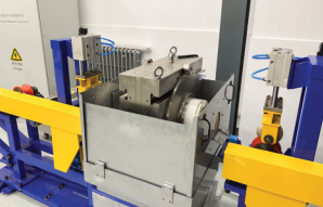
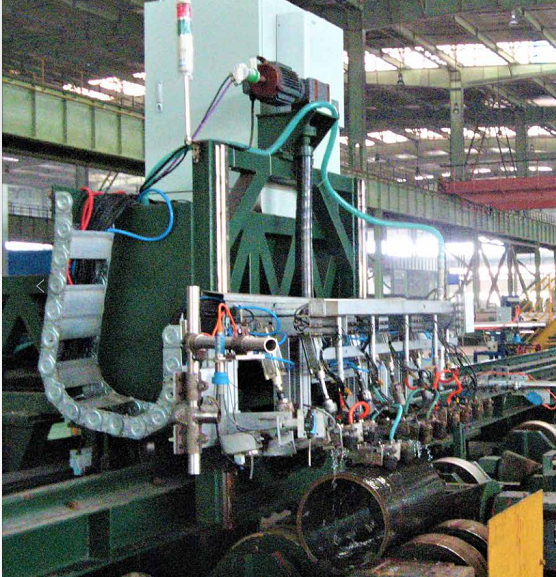
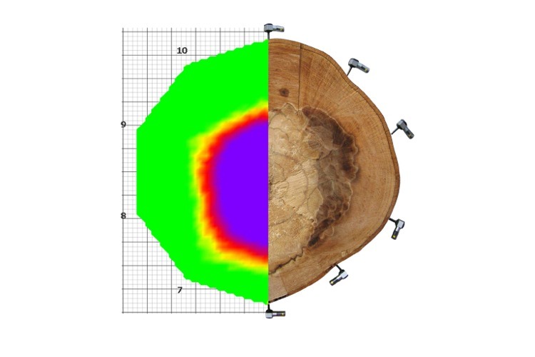
非介入式全场应变形变测量,可用于各种材料压缩和拉伸形变试验中,也可用于冶金,地质,矿产研究和工业领域。
方案详情

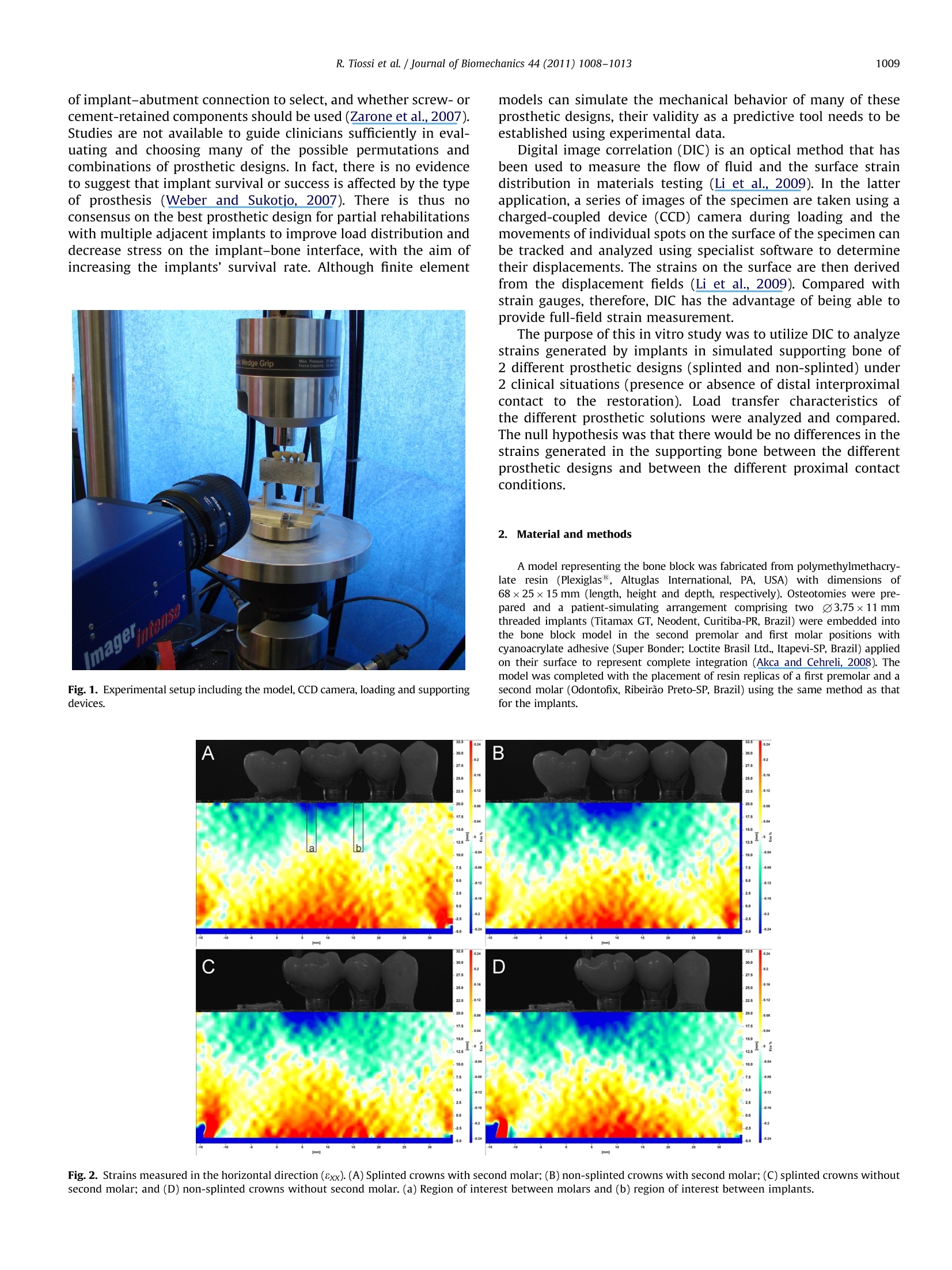
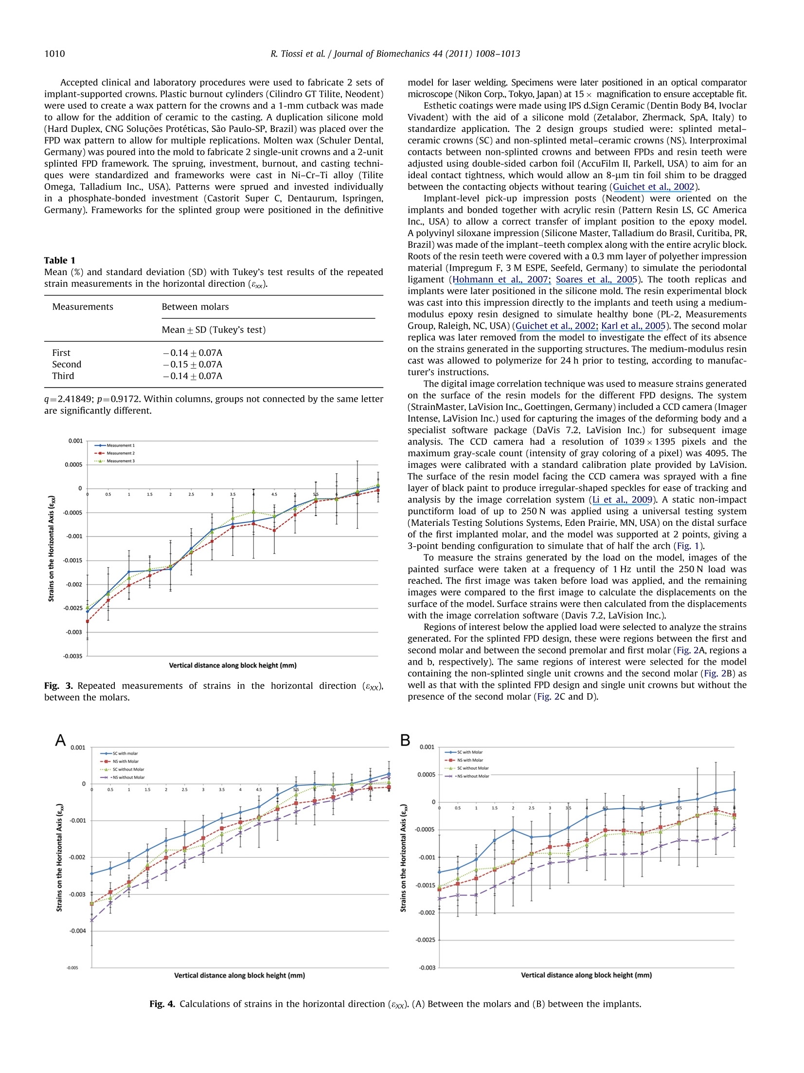
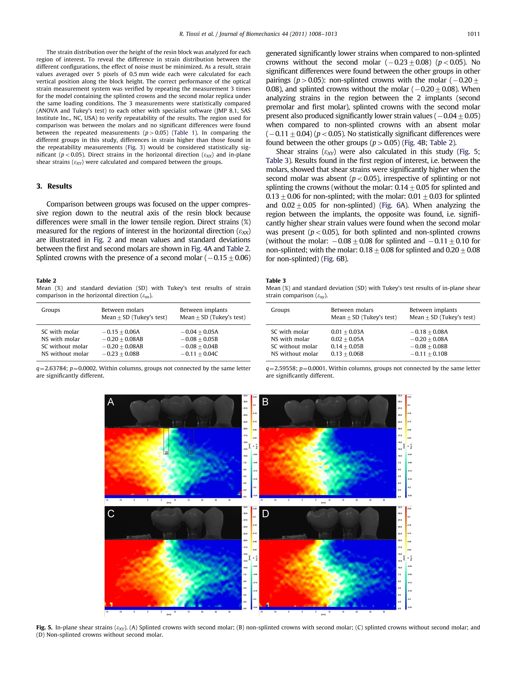
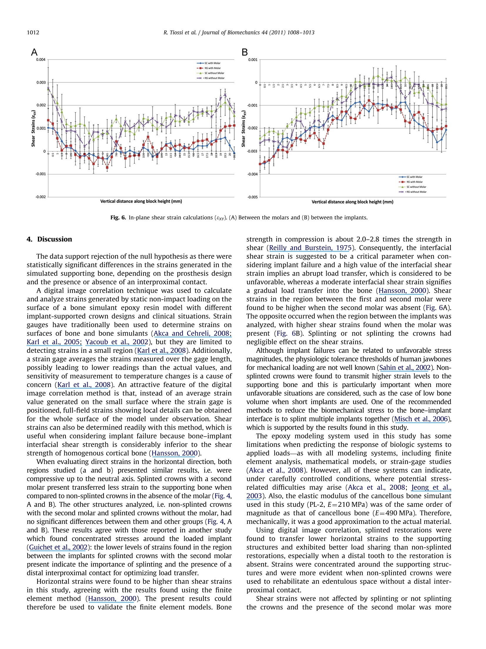
ResearchGateSee discussions, stats, and author profiles for this publication at: https://www.researchgate.net/publication/50288354 Journal of Biomechanics 44 (2011) 1008-1013Contents lists available at ScienceDirect Digital image correlation analysis of the loadtransfer by implant-supported restorations Article in Journal of Biomechanics· March 2011 DOI: 10.1016/j.jbiomech.2011.02.015·Source: PubMed CITATIONS15 tm Journal of Biomechanics journal homepage: www.elsevier.com/locate/jbiomechwww.JBiomech.com Digital image correlation analysis of the load transfer byimplant-supported restorations Rodrigo Tiossi , Lianshan Lin , Renata C.S. Rodrigues, Young C. Heo , Heather J. Conrad ,Maria da Gloria C de Mattos, Ricardo F. Ribeiro a*, Alex S.L. Fok Department of Dental Materials and Prosthodontics, Dental School of Ribeirao Preto, University of Sao Paulo, Av. do Cafe, s/n, Monte Alegre, 14040-904, Ribeirao Preto, Sao Paulo, BrazilD Minnesota Dental Research Center for Biomaterials and Biomechanics, School of Dentistry, University of Minnesota, 16-212 Moos Tower, 515 Delaware Street SE, 55455,Minneapolis, MN,USA ‘Department of Restorative Sciences, School of Dentistry, University of Minnesota, 9-450a Moos Tower, 515 Delaware Street SE, 55455, Minneapolis, MN, USA ARTICLEIN F O ABSTRACT Article history:Accepted 14 February 2011 Keywords:Image correlationImplantsLoad transferProsthodontics This study compared splinted and non-splinted implant-supported prosthesis with and without a distalproximal contact using a digital image correlation method. An epoxy resin model was made withacrylic resin replicas of a mandibular first premolar and second molar and with threaded implantsreplacing the second premolar and first molar. Splinted and non-splinted metal-ceramic screw-retained crowns were fabricated and loaded with and without the presence of the second molar. Asingle-camera measuring system was used to record the in-plane deformation on the model surface at afrequency of 1.0 Hz under a load from 0 to 250 N. The images were then analyzed with specialistsoftware to determine the direct (horizontal) and shear strains along the model. Not splinting thecrowns resulted in higher stress transfer to the supporting implants when the second molar replica wasabsent. The presence of a second molar and an effective interproximal contact contributed to lowerstress transfer to the supporting structures even for non-splinted restorations. Shear strains werehigher in the region between the molars when the second molar was absent, regardless of splinting. Theopposite was found for the region between the implants, which had higher shear strain values whenthe second molar was present. When an effective distal contact is absent, non-splinted implant-supported restorations introduce higher direct strains to the supporting structures under loading. Shearstrains appear to be dependent also on the region within the model,with different regions showingdifferent trends in strain changes in the absence of an effective distal contact. C 2011 Elsevier Ltd. Open access under the Elsevier OA license 1. Introduction The essential difference between natural teeth and osseointe-grated implants is the absence of a periodontal ligament and thuslimited micromovement in the latter, which consequently haveless favorable distributions of forces (Weinberg, 1993) that con-centrate at the crest of the ridge (Rieger et al, 1990). Naturalteeth can move by up to 100 um within its surrounding period-ontal ligament, allowing for a certain degree of misfit of a fixedpartial denture (FPD). In contrast, an osseointegrated implant haslimited movement, less than 10 um, due solely to bone elasticity ( *Corresponding author. Tel.: +55 16 36024046; fax: +55 163633 0999. E-mail a ddresses: rtiossi@yahoo.com (R. Tiossi), linxx643@umn.edu (L. Lin ) , renata@forp.usp.br (R.C . Rodrigues),heoxx002@umn.edu (Y.C. Heo),conr0094@umn.edu (H.J. C o nrad), gloria@forp.usp.br (M.d.de Mattos), rribeiro@forp.usp.br ( R.F. Ribeiro), alexfok@umn.edu (A.S.Fok). ) (Watanabe et al., 2000). Excessive forces at the implant-boneinterface could lead to bone resorption (Riedy et al., 1997). Numerous prosthetic options are available for dental restorationusing multiple adjacent implants. Since complete passivity is difficultto achieve when using splinted restorations supported by multipleimplants (Tiossi et al., 2008), some authors suggest restoring adjacentimplants individually (Solnit and Schneider, 1998) to allow for apassive fit in the resulting restorations (Guichet et al., 2002).Splinting implant-supported restorations is primarily recommendedfor load sharing in distributing the antagonistic occlusal forces(Skalak, 1983) so as to reduce the strains transferred to the period-ontium (Wylie and Caputo, 1991; Yang et al, 1999). Occlusal over-load may induce bone resorption which can lead to marginal boneloss and consequently to implant fractures and implant failure,primarily in the mandibular first molar region (Conrad et al., 2008;Quirynen et al., 1992; Rangert et al., 1995). The ideal restoration of a partially edentulous space remainscontroversial as to the number of implants to be placed, the type of implant-abutment connection to select, and whether screw-orcement-retained components should be used (Zarone et al., 2007).Studies are not available to guide clinicians sufficiently in eval-uating and choosing many of the possible permutations andcombinations of prosthetic designs. In fact, there is no evidenceto suggest that implant survival or success is affected by the typeof prosthesis (Weber and Sukotjo, 2007). There is thus noconsensus on the best prosthetic design for partial rehabilitationswith multiple adjacent implants to improve load distribution anddecrease stress on the implant-bone interface, with the aim ofincreasing the implants’ survival rate. Although finite element models can simulate the mechanical behavior of many of theseprosthetic designs, their validity as a predictive tool needs to beestablished using experimental data. Digital image correlation (DIC) is an optical method that hasbeen used to measure the flow of fluid and the surface straindistribution in materials testing (Li et al, 2009). In the latterapplication, a series of images of the specimen are taken using acharged-coupled device (CCD) camera during loading and themovements of individual spots on the surface of the specimen canbe tracked and analyzed using specialist software to determinetheir displacements. The strains on the surface are then derivedfrom the displacement fields (Li et al., 2009). Compared withstrain gauges, therefore, DIC has the advantage of being able toprovide full-field strain measurement. The purpose of this in vitro study was to utilize DIC to analyzenfstrains generated by implants in simulated supporting bone of2 different prosthetic designs (splinted and non-splinted) under2 clinical situations (presence or absence of distal interproximalcontact to the restoration). Load transfer characteristics ofthe different prosthetic solutions were analyzed and compared.The null hypothesis was that there would be no differences in thestrains generated in the supporting bone between the differentprosthetic designs and between the different proximal contactconditions. 2. Material and methods Fig. 1. Experimental setup including the model, CCD camera,loading and supportingdevices. A model representing the bone block was fabricated from polymethylmethacry-late resin (Plexiglas, Altuglas International, PA, USA) with dimensions of68×25×15 mm (length, height and depth, respectively). Osteotomies were pre-pared and a patient-simulating arrangement comprising two 03.75×11 mmthreaded implants (Titamax GT, Neodent, Curitiba-PR, Brazil) were embedded intothe bone block model in the second premolar and first molar positions withcyanoacrylate adhesive (Super Bonder; Loctite Brasil Ltd., Itapevi-SP, Brazil) appliedon their surface to represent complete integration (Akca and Cehreli, 2008). Themodel was completed with the placement of resin replicas of a first premolar and asecond molar (Odontofix, Ribeirao Preto-SP, Brazil) using the same method as thatfor the implants. Fig.2. Strains measured in the horizontal direction (8xx). (A) Splinted crowns with second molar; (B) non-splinted crowns with second molar;(C) splinted crowns withoutsecond molar; and (D) non-splinted crowns without second molar. (a) Region of interest between molars and (b) region of interest between implants. Accepted clinical and laboratory procedures were used to fabricate 2 sets ofimplant-supported crowns. Plastic burnout cylinders (Cilindro GT Tilite, Neodent)were used to create a wax pattern for the crowns and a 1-mm cutback was madeto allow for the addition of ceramic to the casting. A duplication silicone mold(Hard Duplex, CNG Solucoes Proteticas, Sao Paulo-SP, Brazil) was placed over theFPD wax pattern to allow for multiple replications. Molten wax (Schuler Dental,Germany) was poured into the mold to fabricate 2 single-unit crowns and a 2-unitsplinted FPD framework. The spruing, investment, burnout, and casting techni-ques were standardized and frameworks were cast in Ni-Cr-Ti alloy (TiliteOmega, Talladium Inc., USA). Patterns were sprued and invested individuallyin a phosphate-bonded investment (Castorit Super C, Dentaurum, Ispringen,Germany). Frameworks for the splinted group were positioned in the definitive Table 1 Mean (%) and standard deviation (SD) with Tukey's test results of the repeatedstrain measurements in the horizontal direction (8xx). Measurements Between molars Mean±SD (Tukey's test) First -0.14+0.07A Second -0.15+0.07A Third -0.14±0.07A q=2.41849;p=0.9172. Within columns, groups not connected by the same letterare significantly different. Fig. 3. Repeated measurements of strains in the horizontal direction (8xx),between the molars. model for laser welding. Specimens were later positioned in an optical comparatormicroscope (Nikon Corp., Tokyo, Japan) at 15x magnification to ensure acceptable fit. Esthetic coatings were made using IPS d.Sign Ceramic (Dentin Body B4, IvoclarVivadent) with the aid of a silicone mold (Zetalabor, Zhermack, SpA, Italy) tostandardize application. The 2 design groups studied were: splinted metal-ceramic crowns (SC) and non-splinted metal-ceramic crowns (NS). Interproximalcontacts between non-splinted crowns and between FPDs and resin teeth wereadjusted using double-sided carbon foil (AccuFilm II, Parkell, USA) to aim for anideal contact tightness, which would allow an 8-um tin foil shim to be draggedbetween the contacting objects without tearing (Guichet et al., 2002). Implant-level pick-up impression posts (Neodent) were oriented on theimplants and bonded together with acrylic resin (Pattern Resin LS, GC AmericaInc., USA) to allow a correct transfer of implant position to the epoxy model.A polyvinyl siloxane impression (Silicone Master, Talladium do Brasil, Curitiba, PR,Brazil) was made of the implant-teeth complex along with the entire acrylic block.Roots of the resin teeth were covered with a 0.3 mm layer of polyether impressionmaterial (Impregum F, 3M ESPE, Seefeld, Germany) to simulate the periodontalligament (Hohmann et al., 2007; Soares et al., 2005). The tooth replicas andimplants were later positioned in the silicone mold. The resin experimental blockwas cast into this impression directly to the implants and teeth using a medium-modulus epoxy resin designed to simulate healthy bone (PL-2, MeasurementsGroup, Raleigh, NC, USA) (Guichet et al., 2002; Karl et al.,2005). The second molarreplica was later removed from the model to investigate the effect of its absenceon the strains generated in the supporting structures. The medium-modulus resincast was allowed to polymerize for 24 h prior to testing, according to manufac-turer's instructions. The digital image correlation technique was used to measure strains generatedon the surface of the resin models for the different FPD designs. The system(StrainMaster, LaVision Inc., Goettingen, Germany) included a CCD camera (ImagerIntense, LaVision Inc.) used for capturing the images of the deforming body and aspecialist software package (DaVis 7.2, LaVision Inc.) for subsequent imageanalysis. The CCD camera had a resolution of 1039×1395 pixels and themaximum gray-scale count (intensity of gray coloring of a pixel) was 4095. Theimages were calibrated with a standard calibration plate provided by LaVision.The surface of the resin model facing the CCD camera was sprayed with a finelayer of black paint to produce irregular-shaped speckles for ease of tracking andanalysis by the image correlation system (Li et al., 2009). A static non-impactpunctiform load of up to 250 N was applied using a universal testing system(Materials Testing Solutions Systems, Eden Prairie, MN, USA) on the distal surfaceof the first implanted molar, and the model was supported at 2 points, giving a3-point bending configuration to simulate that of half the arch (Fig. 1). To measure the strains generated by the load on the model, images of thepainted surface were taken at a frequency of 1 Hz until the 250 N load wasreached. The first image was taken before load was applied, and the remainingimages were compared to the first image to calculate the displacements on thesurface of the model.Surface strains were then calculated from the displacementswith the image correlation software (Davis 7.2, LaVision Inc.). Regions of interest below the applied load were selected to analyze the strainsgenerated. For the splinted FPD design, these were regions between the first andsecond molar and between the second premolar and first molar (Fig. 2A, regions aand b, respectively). The same regions of interest were selected for the modelcontaining the non-splinted single unit crowns and the second molar (Fig. 2B) aswell as that with the splinted FPD design and single unit crowns but without thepresence of the second molar (Fig. 2C and D). Fig. 4. Calculations of strains in the horizontal direction (8xx). (A) Between the molars and (B) between the implants. The strain distribution over the height of the resin block was analyzed for eachregion of interest. To reveal the difference in strain distribution between thedifferent configurations, the effect of noise must be minimized. As a result, strainvalues averaged over 5 pixels of 0.5 mm wide each were calculated for eachvertical position along the block height. The correct performance of the opticalstrain measurement system was verified by repeating the measurement 3 timesfor the model containing the splinted crowns and the second molar replica underthe same loading conditions. The 3 measurements were statistically compared(ANOVA and Tukey's test) to each other with specialist software (JMP 8.1, SASInstitute Inc., NC, USA) to verify repeatability of the results. The region used forcomparison was between the molars and no significant differences were foundbetween the repeated measurements (p>0.05) (Table 1). In comparing thedifferent groups in this study, differences in strain higher than those found inthe repeatability measurements (Fig. 3) would be considered statistically sig-nificant (p<0.05). Direct strains in the horizontal direction (8xx) and in-planeshear strains (8xy) were calculated and compared between the groups. 3. Results Comparison between groups was focused on the upper compres-sive region down to the neutral axis of the resin block becausedifferences were small in the lower tensile region. Direct strains (%)measured for the regions of interest in the horizontal direction (8xx)are illustrated in Fig. 2 and mean values and standard deviationsbetween the first and second molars are shown in Fig. 4A and Table 2.Splinted crowns with the presence of a second molar (-0.15±0.06) Table 2 Mean (%) and standard deviation (SD) with Tukey’s test results of straincomparison in the horizontal direction (8xx). Groups Between molars Between implants Mean±SD (Tukey’s test) Mean ±SD (Tukey's test) SC with molar -0.15±0.06A -0.04±0.05A NS with molar -0.20±0.08AB -0.08±0.05B SC without molar -0.20±0.08AB -0.08+0.04B NS without molar -0.23+0.08B -0.11±0.04C generated significantly lower strains when compared to non-splintedcrowns without the second molar (-0.23±0.08) (p<0.05). Nosignificant differences were found between the other groups in otherpairings (p>0.05): non-splinted crowns with the molar (-0.20±0.08), and splinted crowns without the molar (-0.20±0.08). Whenanalyzing strains in the region between the 2 implants (secondpremolar and first molar), splinted crowns with the second molarpresent also produced significantly lower strain values (-0.04±0.05)when compared to non-splinted crowns with an absent molar(-0.11±0.04)(p<0.05).No statistically significant differences werefound between the other groups (p>0.05)(Fig. 4B; Table 2). Shear strains (8xy) were also calculated in this study (Fig. 5;Table3). Results found in the first region of interest, i.e. between themolars, showed that shear strains were significantly higher when thesecond molar was absent (p<0.05), irrespective of splinting or notsplinting the crowns (without the molar: 0.14±0.05 for splinted and0.13±0.06 for non-splinted; with the molar: 0.01 ±0.03 for splintedand 0.02±0.05 for non-splinted) (Fig. 6A). When analyzing theregion between the implants, the opposite was found, i.e. signifi-cantly higher shear strain values were found when the second molarwas present (p<0.05), for both splinted and non-splinted crowns(without the molar: -0.08±0.08 for splinted and -0.11±0.10 fornon-splinted; with the molar: 0.18±0.08 for splinted and 0.20±0.08for non-splinted) (Fig. 6B). Table 3 Mean (%) and standard deviation (SD) with Tukey’s test results of in-plane shearstrain comparison (8xy). Groups Between molars Between implants Mean ±SD (Tukey’s test) Mean ± SD (Tukey’s test) SC with molar 0.01±0.03A -0.18+0.08A NS with molar 0.02+0.05A -0.20±0.08A SC without molar 0.14+0.05B -0.08+0.08B NS without molar 0.13+0.06B -0.11±0.10B q=2.63784; p=0.0002. Within columns, groups not connected by the same letterare significantly different. q=2.59558; p=0.0001. Within columns, groups not connected by the same letterare significantly different. Fig. 5. In-plane shear strains (8xy). (A) Splinted crowns with second molar; (B) non-splinted crowns with second molar; (C)splinted crowns without second molar; and(D)Non-splinted crowns without second molar. Fig. 6. In-plane shear strain calculations (8xy). (A) Between the molars and (B) between the implants. The data support rejection of the null hypothesis as there werestatistically significant differences in the strains generated in thesimulated supporting bone, depending on the prosthesis designand the presence or absence of an interproximal contact. A digital image correlation technique was used to calculateand analyze strains generated by static non-impact loading on thesurface of a bone simulant epoxy resin model with differentimplant-supported crown designs and clinical situations. Straingauges have traditionally been used to determine strains onsurfaces of bone and bone simulants (Akca and Cehreli, 2008;Karl et al., 2005; Yacoub et al., 2002), but they are limited todetecting strains in a small region (Karl et al., 2008). Additionally,a strain gage averages the strains measured over the gage length,possibly leading to lower readings than the actual values, andsensitivity of measurement to temperature changes is a cause ofconcern (Karl et al., 2008). An attractive feature of the digitalimage correlation method is that, instead of an average strainvalue generated on the small surface where the strain gage ispositioned, full-field strains showing local details can be obtainedfor the whole surface of the model under observation. Shearstrains can also be determined readily with this method, which isuseful when considering implant failure because bone-implantinterfacial shear strength is considerably inferior to the shearstrength of homogenous cortical bone (Hansson, 2000). When evaluating direct strains in the horizontal direction, bothregions studied (a and b) presented similar results, i.e. werecompressive up to the neutral axis. Splinted crowns with a secondmolar present transferred less strain to the supporting bone whencompared to non-splinted crowns in the absence of the molar (Fig. 4,A and B). The other structures analyzed, i.e. non-splinted crownswith the second molar and splinted crowns without the molar, hadno significant differences between them and other groups (Fig. 4, Aand B). These results agree with those reported in another studywhich found concentrated stresses around the loaded implant(Guichet et al., 2002): the lower levels of strains found in the regionbetween the implants for splinted crowns with the second molarpresent indicate the importance of splinting and the presence of adistal interproximal contact for optimizing load transfer. Horizontal strains were found to be higher than shear strainsin this study, agreeing with the results found using the finiteelement method (Hansson, 2000). The present results couldtherefore be used to validate the finite element models. Bone strength in compression is about 2.0-2.8 times the strength inshear (Reilly and Burstein, 1975). Consequently, the interfacialshear strain is suggested to be a critical parameter when con-sidering implant failure and a high value of the interfacial shearstrain implies an abrupt load transfer, which is considered to beunfavorable, whereas a moderate interfacial shear strain signifiesa gradual load transfer into the bone (Hansson, 2000). Shearstrains in the region between the first and second molar werefound to be higher when the second molar was absent (Fig.6A).The opposite occurred when the region between the implants wasanalyzed, with higher shear strains found when the molar waspresent (Fig. 6B). Splinting or not splinting the crowns hadnegligible effect on the shear strains. Although implant failures can be related to unfavorable stressmagnitudes, the physiologic tolerance thresholds of human jawbonesfor mechanical loading are not well known (Sahin et al., 2002). Non-splinted crowns were found to transmit higher strain levels to thesupporting bone and this is particularly important when moreunfavorable situations are considered, such as the case of low bonevolume when short implants are used. One of the recommendedmethods to reduce the biomechanical stress to the bone-implantinterface is to splint multiple implants together (Misch et al., 2006),which is supported by the results found in this study. The epoxy modeling system used in this study has somelimitations when predicting the response of biologic systems toapplied loads-as with all modeling systems, including finiteelement analysis, mathematical models, or strain-gage studies(Akca et al., 2008). However, all of these systems can indicate,under carefully controlled conditions, where potential stress-related difficulties may arise (Akca et al., 2008; Jeong et al,2003).Also, the elastic modulus of the cancellous bone simulantused in this study (PL-2, E=210 MPa) was of the same order ofmagnitude as that of cancellous bone (E=490 MPa). Therefore,mechanically, it was a good approximation to the actual material. Using digital image correlation, splinted restorations werefound to transfer lower horizontal strains to the supportingstructures and exhibited better load sharing than non-splintedrestorations, especially when a distal tooth to the restoration isabsent. Strains were concentrated around the supporting struc-tures and were more evident when non-splinted crowns wereused to rehabilitate an edentulous space without a distal inter-proximal contact. Shear strains were not affected by splinting or not splintingthe crowns and the presence of the second molar was more effective in reducing shear strains in the regions between themolars. Conflict of interest statement None declared. Acknowledgements This investigation was supported by Research Grant No. 2007/06995-3 from Sao Paulo State Research Foundation (FAPESP) andby Research Grant No. 2450/09-7 from Coordenacao de Aperfeicoamento de Pessoal de Nivel Superior (CAPES). Rodrigo Tiossi would like to thank the Minnesota DentalResearch Center for Biomaterials and Biomechanics for hostinghis visit and for providing the Digital Image Correlation equip-ment to support his study. The authors wish to thank NEODENT for supplying the implantcomponents. References Akca, K., Cehreli, M.C., 2008.A photoelastic and strain-gauge analysis of interfaceforce transmission of internal-cone implants. International Journal of Period-ontics and Restorative Dentistry 28, 391-399. Akca,K., Fanuscu,M.I.. Caputo,A.A., 2008.Effect of compromised cortical bone onimplant load distribution. Journal of Prosthodontics 17,616-620. Conrad, H.J., Schulte, J.K., Vallee, M.C., 2008. Fractures related to occlusal overloadwith single posterior implants: a clinical report. Journal of Prosthetic Dentistry99,251-256. Weber,H.P.,Sukotjo, C., 2007. Does the type of implant prosthesis affect outcomesin the partially edentulous patient? International Journal of Oral and Max-illofacial Implants 22, 140-172. Guichet, D.L., Yoshinobu, D., Caputo, A.A.,2002. Effect of splinting and interprox-imal contact tightness on load transfer by implant restorations. Journal ofProsthetic Dentistry 87, 528-535. Hansson, S., 2000. Implant-abutment interface: biomechanical study of flat topversus conical. Clinical Implant Dentistry and Related Research 2,33-41. Hohmann, A.. Wolfram, U.,Geiger, M., Boryor, A.. Sander, C.. Faltin,R., Faltin, K.,Sander, F.G.,2007. Periodontal ligament hydrostatic pressure with areas ofroot resorption after application of a continuous torque moment. AngleOrthodontist 77, 653-659. Jeong, C.M., Caputo, A.A., Wylie, R.S., Son, S.C., Jeon, Y.C., 2003. Bicorticallystabilized implant load transfer. International Journal of Oral andMaxillofacialImplants 18,59-65. Karl, M., Rosch, S., Graef, F., Taylor, T.D., Heckmann, S.M., 2005. Strain situationafter fixation of three-unit ceramic veneered implant superstructures. ImplantDentistry 14, 157-165. Karl, M., Wichmann, M.G., Winter, W.,Graef, F., Taylor, T.D., Heckmann, S.M.,2008.Influence of fixation mode and superstructure span upon strain developmentof implant fixed partial dentures. Journal of Prosthodontics 17, 3-8. Li, J., Fok, A.S., Satterthwaite,J., Watts, D.C., 2009. Measurement of the full-fieldpolymerization shrinkage and depth of cure of dental composites using digitalimage correlation. Dental Materials 25, 582-588. Misch, C.E.,Steignga,J., Barboza, E.,Misch-Dietsh, F.,Cianciola, L.J., Kazor, C., 2006.Short dental implants in posterior partial edentulism: a multicenter retro-spective 6-year case series study. Journal of Periodontology 77, 1340-1347. Quirynen,M., Naert, I, van Steenberghe, D., 1992. Fixture design and overloadinfluence marginal bone loss and fixture success in the Branemark system.Clinical Oral Implants Research 3, 104-111. Rangert,B., Krogh, P.H., Langer, B., Van Roekel, N., 1995. Bending overload andimplant fracture: a retrospective clinical analysis.International Journal of Oraland Maxillofacial Implants 10, 326-334. Reilly, D.T., Burstein, A.H., 1975. The elastic and ultimate properties of compactbone tissue.Journal of Biomechanics 8, 393-405. Riedy, S.L.. Lang, B.R., Lang, B.E., 1997. Fit of implant frameworks fabricated by different techniques. Journal of Prosthetic Dentistry 78,596-604. Rieger, M.R., Mayberry, M., Brose, M.O., 1990. Finite element analysis of sixendosseous implants. Journal of Prosthetic Dentistry 63, 671-676. Sahin, S., Cehreli, M.C., Yalcin, E., 2002. The influence of functional forces on thebiomechanics of implant-supported prostheses-a review. Journal of Dentistry30,271-282. Skalak, R., 1983. Biomechanical considerations in osseointegrated prostheses.Journal of Prosthetic Dentistry 49, 843-848. Soares, C.L. Pizi, E.C.. Fonseca, R.B.. Martins, L.R., 2005. Influence of root embed-ment material and periodontal ligament simulation on fracture resistancetests. Brazilian Oral Research 19. 11-16. Solnit, G.S.Schneider,R.L., 1998. An alternative to splinting multipleimplants: useof the ITI system. Journal of Prosthodontics 7, 114-119. Tiossi, R.. Rodrigues, R.C., de Mattos Mda, G., Ribeiro, R.F., 2008. Comparativeanalysis of the fit of 3-unit implant-supported frameworks cast in nickel-chromium and cobalt-chromium alloys and commercially pure titanium aftercasting,laser welding, and simulated porcelain firings. International Journal ofProsthodontics 21, 121-123. Watanabe, F., Uno, I., Hata, Y.. Neuendorff, G.. Kirsch, A., 2000. Analysis of stressdistribution in a screw-retained implant prosthesis.International Journal ofOral and Maxillofacial Implants 15, 209-218. Weinberg, L.A., 1993. The biomechanics of force distribution in implant-supportedprostheses.International Journal of Oral and Maxillofacial Implants 8, 19-31.Wylie, R.S., Caputo, A.A., 1991. Fixed cantilever splints on teeth with normal and reduced periodontal support. Journal of Prosthetic Dentistry 66,737-742. Yacoub, N., Ismail, Y.H., Mao, L.L, 2002. Transmission of bone strain in thecraniofacial bones of edentulous human skulls upon dental implant loading.Journal of Prosthetic Dentistry 88, 192-199. Yang, H.S., Lang, L.A., Felton, D.A., 1999. Finite element stress analysis on the effectof splinting in fixedpartial dentures. Journal of Prosthetic Dentistry 81,721-728. Zarone, F., Sorrentino,R., Traini, T., Di lorio, D., Caputi, S.,2007. Fracture resistanceof implant-supported screw- versus cement-retained porcelain fused to metalsingle crowns: SEM fractographic analysis. Dental Materials 23, 296-301. Elsevier Ltd. Open access under the Elsevier OA licensedoi:j.jbiomech. View publication stats This study compared splinted and non-splinted implant-supported prosthesis with and without a distal proximal contact using a digital image correlation method. Anepoxy resin model was made withacrylic resin replicas of a mandibular first premolar and second molar and with threaded implantsreplacing the second premolar and first molar. Splinted and non-splinted metal–ceramic screw-retained crowns were fabricated and loaded with and without the presence of the second molar.Asingle-camera measuring system was used to record the in-plane deformation on the model surface at afrequency of 1.0 Hz under a load from 0 to 250N. The images were then analyzed with specialistsoftware to determine the direct (horizontal) and shear strains along the model.Not splinting thecrowns resulted in higher stress transfer to the supporting implants when the second molar replica wasabsent. The presence of a second molar and an effective interproximal contact contributed to lowerstress transfer to the supporting structures even forn on-splinted restorations. Shear strains werehigher in the region between the molars when the second molar was absent, regardless of splinting.The opposite was found for the region between the implants, which had higher shear strain values whenthe second molar was present. When an effective distal contact is absent,non-splinted implant-supported restorations introduce higher direct strains to the supporting structures underloading. Shear strains appear to be dependent also on the region within the model, with different regions showingdifferent trends in strain changes in the absence of an effective distal contact.
确定

还剩5页未读,是否继续阅读?

产品配置单

北京欧兰科技发展有限公司为您提供《种植牙中载荷,应变检测方案(其它无损检测仪器/设备)》,该方案主要用于牙齿中载荷,应变检测,参考标准--,《种植牙中载荷,应变检测方案(其它无损检测仪器/设备)》用到的仪器有LaVision StrainMaster材料应变形变成像测量系统
推荐专场


相关方案
更多
该厂商其他方案
更多