


方案详情
文
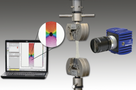
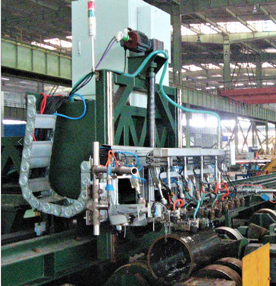
采用德国LaVision公司的数字图像相关分析(DIC)设备,对种植牙牙冠材料对骨组织应变影响进行了测量和分析。
方案详情

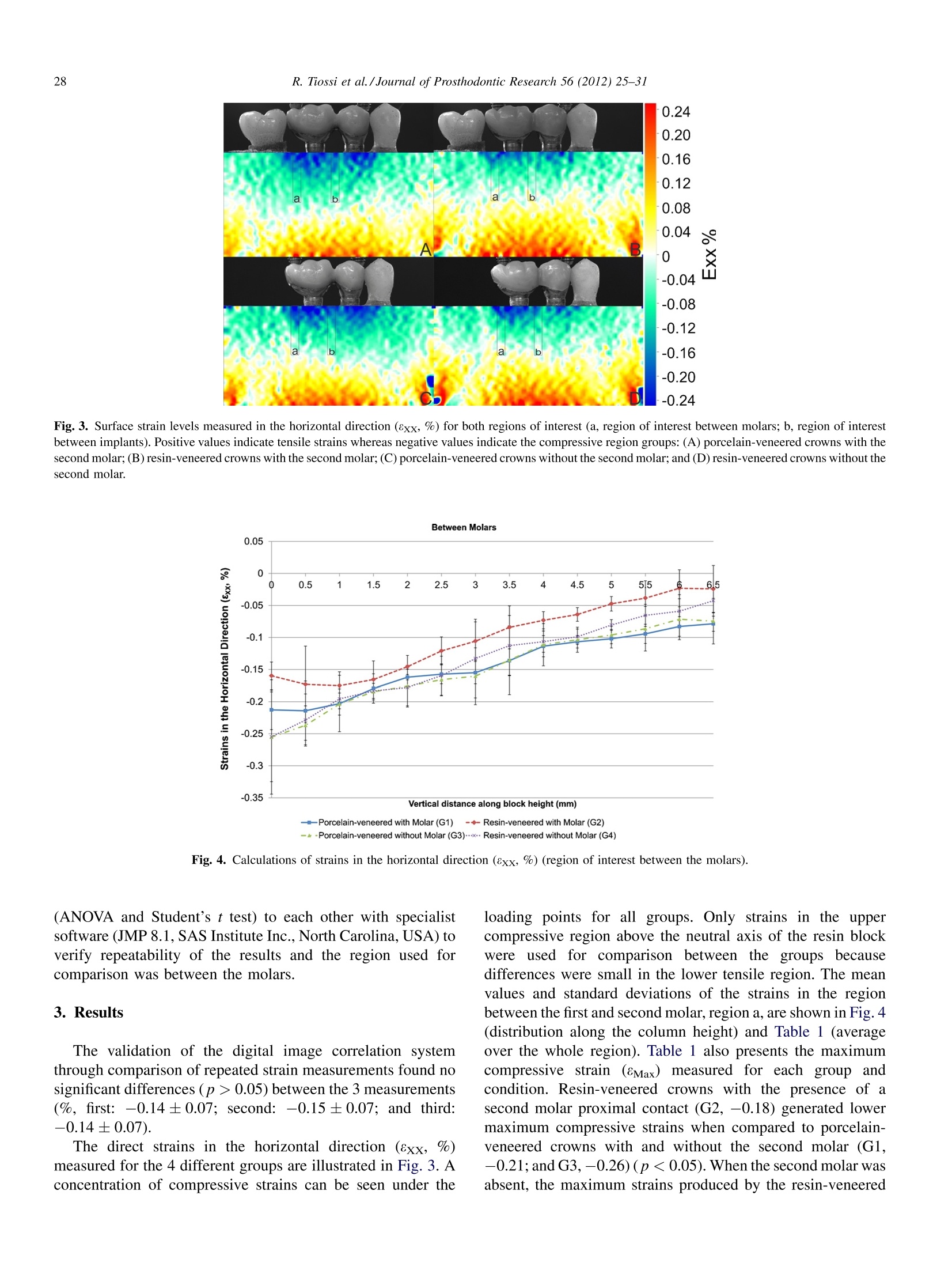
ResearchGateSee discussions, stats, and author profiles for this publication at: https://www.researchgate.net/publication/51229724 Available online at www.sciencedirect.comJournal of Prosthodontic Research 56 (2012)25-31www.elsevier.com/locate/jporOriginal article View publication stats Digital image correlation analysis on theinfluence of crown material in implant-supported prostheses on bone straindistribution All content following this page was uploaded by Ricardo Faria Ribeiro on 23 December 2016. The user has requested enhancement of the downloaded file. All in-text references underlined in blue are added to the original documentand are linked to publications on ResearchGate, letting you access and read them immediately. Journal ofProsthodonticResearch A digital image correlation analysis on the influence of crown materialin implant-supported prostheses on bone strain distribution Rodrigo Tiossi DDS, MSc, PhD, Lianshan Lin BEng, PhD, Heather Joan Conrad DMD, MSc, FACP, FRCD(C), Renata C.S. Rodrigues DDS, MSc, PhD,Young Cheul Heo BS, Maria da Gloria Chiarello de Mattos DDS, MSc, PhD, Alex Sui-Lun Fok BEng, BA, MSc, PhD, Ricardo Faria Ribeiro DDS,MSc, PhDa.* Department of Dental Materials and Prosthodontics, Dental School of Ribeirāo Preto, University of Sāo Paulo, Av. do Cafe, s/n-Monte Alegre, Ribeirāo Preto, Sāo Paulo 14040-904, Brazil Minnesota Dental Research Center for Biomaterials and Biomechanics, School of Dentistry, University of Minnesota, Minneapolis, MN, USA Department of Restorative Sciences, School of Dentistry, University of Minnesota, Minneapolis, MN, USA Received 18 January 2011; received in revised form 3 May2011; accepted 24 May 2011 Abstract Purpose: A digital image correlation (DIC) method for full-field surface strain measurement was used to analyze the effect of two veneeringmaterials for implant supported crowns on the strain distribution within the surrounding bone. Methods: An epoxy resin model of a bone block was made by housing acrylic resin replicas of a mandibular first premolar and second molartogether with threaded implants replacing the second premolar and first molar. Porcelain-veneered (G1 and G3) and resin-veneered (G2 and G4)screw-retained splinted crowns were fabricated and loaded with (G1 and G2) and without (G3 and G4) the presence of the second molar replica. A2-dimensional DIC measuring system was used to record surface deformation of the bone block model at a frequency of 1.0 Hz during applicationof a 250-N load. Results: Maximum compressive strains (8xx,%) were found for the following regions: between molars,G1 (-0.21), G2(-0.18), G3(-0.26), andG4 (-0.25); between implants,G1 (-0.19), G2(-0.13), G3 (-0.19), and G4 (-0.14). The magnitude of strains in the simulated bone block withthe resin-veneered crowns was lower than that with porcelain-veneered crowns, irrespective of the presence or absence of the second molar.Conclusions: The softer resin veneer helped to spread the load more evenly amongst the supporting teeth and implants, thus reducing the strains inthe simulant bone block.Conversely, using the harder porcelain veneer resulted in the load being concentrated within one or two teeth or implants,thus leading to higher strain values in the bone block. C 2011 Japan Prosthodontic Society. Published by Elsevier Ireland. All rights reserved. Keywords: Image correlation; Dental implants; Load transfer; Dental materials; Fixed partial denture 1. Introduction The successful osseointegration and long-term survival oforal implants depend on several biomechanical factors. Theselection of appropriate implant position, prosthesis design,biocompatibility and mechanical and physical properties of thematerials is critical for the longevity, stability and properfunction of the implant prosthesis [1-6]. Since no micromove-ment is provided by a fully osseointegrated dental implant, all ( * Corresponding author. T e l.: +55 1 6 3 602 4046; fax: +55 1 6 3 6 33 0999. E-mail address: r r ibeiro@forp.usp.br (R.F. Ri b eiro). ) stresses and impact forces applied to the implant-supportedprosthesis are directly transmitted to the surrounding bonethrough the implant-bone interface. Consequently, overstres-sing the implants may cause bone microfractures [7] and lead tothe occurrence of an increased rate of marginal bone loss [8].Since the nature and magnitude of loads necessary to causeimplant loosening is unknown, it is recommended that occlusalforces be kept to a minimum [6]. The design and material of dental superstructures influencethe loading of dental implants and, hence, the deformation ofthe bone [9]. Ceramic materials are commonly used forveneering implant-supported prostheses as they provide greatimprovements to the esthetics of implant restorations;[10]. ( 1 883-1958/$ - s e e fr o nt matter C 20 1 1 Ja pa n Pros t hodontic Society. Publ i shed by Elsevier Ireland. All r igh t s reserved. doi:1 0 .1 0 16/j . jpor.2011 . 05.003 ) However, porcelain is not a shock-absorbing material, andforces developed at the occlusal surface will be directlytransmitted to the prosthesis, the implant, or the bone interface,unless they are interrupted in some way [6,11]. One of theconcepts developed to distribute the stresses more evenlyaround dental implants is to dampen the occlusal forces with theuse of shock-absorbing materials, suchas acrylic andmicrofilled resins [5,7,12]. Studies comparing the shock-absorbing behavior of different veneering materials found that,when harder and stiffer materials were used, a higher impactforce was transmitted to the fixture and with a shorter rise time.Conversely, the more resilient the material, the longer was therise time and the smaller was the stress [12,13]. Finite element (FE) modeling has proven to be a useful toolfor analyzing the mechanical behavior of dental implants withdifferent prosthetic designs. Still, FE studies would benefitfrom the use of an accurate experimental tool to validate theirresults. However, experimental studies involving direct strainmeasurement of dental restorations to date have only providedlimited local measurements [14-16],which are not sufficient tofully demonstrate the mechanical behavior of the restorations orto validate the 2- or even 3-dmensional strain distributionspredicted by FE modeling [17,18]. Digital image correlation(DIC) is an optical method initially developed to measure theflow of fluid and later the surface strain distribution in materialsunder mechanical testing. The method works by taking a seriesof images of a specimen during loading and then tracking thedisplacement of individual speckles on the surface of thespecimen. Subsequent analysis with specialist software derivesthe strains on the surface from the displacement fields,providing a full-field strain measurement [19]. Using the DIC method, this in vitro study measured strainsgenerated by implants of 2 different veneering materials(ceramic and resin) in simulated supporting bone under 2clinical situations (presence or absence of a distal proximalcontact to the restoration). The load transfer characteristics ofthe different prosthetic solutions were analyzed and compared.The null hypothesis was that there would be no differences inthe strains generated in the supporting bone between the caseswith different veneering materials and between those withdifferent proximal contact conditions. 2. Materials and methods A polymethylmethacrylate model (Plexiglas, AltuglasInternational,l, Philadelphia,.USA) with dimensions of68 mm×25 mm × 15 mm (length, height and depth, respec-tively) was fabricated to represent a bone block. The model wasmade with socket spaces for teeth and implants to simulate partoftheeaarchofapartially edentulous patient.Two03.75 mm ×11 mm threaded implants (Titamax GT, Neodent,Curitiba,PR, Brazil) were embedded into the bone block modelin the second premolar andfirst molar positionswithcyanoacrylate adhesive (Super Bonder; Loctite Brasil Ltd.,Itapevi, SP, Brazil) applied on their surface to representcomplete integration [20]. The model was completed with theplacement of acrylic replicas of a first premolar and a second Fig. 1. Fabrication of the frameworks used in the study. (A) Waxing of theframeworks with thickness of the metal framework of at least 0.5 mm; (B)silicone wall to standardize the esthetic veneers with 1 mm thickness all-aroundthe metal framework; and (C) connector design and finished morphology of thefixed partial dentures with standardized veneer thicknesses. molar (Odontofix, Ribeirao Preto, SP,Brazil) using the samemethod as that for the implants. Accepted clinical and laboratory procedures were used tofabricate 2 sets of implant-supported 2-unit splinted fixedpartial denture (FPD) (Fig. 1) by an experienced dentaltechnician with thickness of the metal framework of at least0.5 mm and with a 1 mm cutback to allow for the addition of theveneering materials (Fig. 1A and B). Framework design wasidentical for both veneering materials. However, retentivebeads were added on the surface of the resin veneered crowns toallow better retention of the esthetic veneer. A silicone wall wasmade to standardize the esthetic veneering of each crown with a1 mm thickness all-around the metal framework (Fig. 1B andC). The spruing, investment, burnout, and casting techniqueswere standardized and frameworks were cast in Ni-Cr-Ti alloy (Tilite Omega, Talladium Inc., USA). Patterns were sprued andinvestedindividually inaphosphate-bonded investment(Castorit Super C, Dentaurum, Ispringen, Germany). Allframeworks were placed in the bone block model for laserwelding. The specimens were later placed under an opticalcomparator microscope (Nikon Corp., Tokyo, Japan) at 15×magnification to ensure acceptable fit. The esthetic coatings were made with IPS d.Sign Porcelain(Dentin Body B4, Ivoclar Vivadent, Schaan, Liechtenstein) andSR Chromasit microfilled composite (Dentin Body 1D, IvoclarVivadent) with the aid of a silicone putty matrix (Zetalabor,Zhermack, SpA, Italy) to standardize the application. The fourgroups considered were: porcelain-veneered (G1 and G3) andresin-veneered (G2 and G4), with (G1 and G2) and without (G3and G4) the presence of a second molar proximal contact.Interproximal contacts between the FPDs and the resin teethwere adjusted using a double-sided carbon foil (AccuFilm II,Parkell, USA). The contact tightness was aimed to allow an 8-um tin foil shim to be dragged between the contacting objectswithout tearing [21]. The strains generated on the surface of the resin models forthe different FPD designs were calculated with the aid of adigital image correlation system. The system (StrainMaster,LaVision Inc., Goettingen, Germany) included a charged-coupled device (CCD) camera (Imager Intense, LaVision Inc.)used for capturing the images of the deforming body and aspecialist software package (DaVis 7.2, LaVision Inc.) forsubsequent image analysis. The resolution of the CCD camerawas of 1039 × 1395 pixels and the maximum gray-scale count(intensity of gray coloring of a pixel) was 4095. A standardcalibration plate provided by LaVision was used to calibrate theimages.The surface of the resin model facing the CCD camerawas sprayed with a fine layer of black paint to produceirregular-shaped speckles for ease of tracking and analysis bythe image correlation system [19]. Vertical non-impact pointloads of up to 250-N in total were simultaneously applied to thecrowns above the implants replacing the second premolar and Fig.2. Experimental setup including the model with loading and supportingdevices. first molar using a universal testing system (Materials TestingSolutions Systems, Eden Prairie, MN, USA). The model wassupported at 2 points, giving a 3-point bending configuration tosimulate that of half the arch (Fig.2). Images of the painted surface were taken at a frequency of1 Hz during application of the 250-N load. The first image wastaken before loading was applied, and the remaining imageswere compared to the first image to calculate the displacementson the surface of the model. Direct strains were then derivedfrom the displacements with the image correlation software(Davis 7.2, LaVision Inc.). Regions of interest below theapplied load were selected between the first and second molarsand between the second premolar and first molar (Fig.3,regions a and b, respectively), for which the induced surfacestrains over the height of the resin block were calculated. Thesame regions of interest were selected for all the groupsanalyzed in this study. Direct strains in the horizontal direction(8xx, %) were calculated for comparison between the groupsand ANOVA with Student’s t test was applied to check forstatistical significance in the differences. The effect of noisemust be minimized in order to reveal the difference in straindistribution between the different configurations. As a result,strain values averaged over a horizontal distance of 5 pixels,each of 0.5 mm wide, were calculated for each vertical positionalong the height of the regions of interest. Maximumcompressive strains were also calculated for each groupanalyzed in the study. Verification of the correct performance of the optical strainmeasurement system was done by repeating 3 times the samemeasurement for the model with porcelain-veneered crownsand with the second molar replica, under the same loadingconditions. The 3 measurements were statistically compared Fig. 3. Surface strain levels measured in the horizontal direction (8xx, %) for both regions of interest (a, region of interest between molars; b,region of interestbetween implants). Positive values indicate tensile strains whereas negative values indicate the compressive region groups: (A) porcelain-veneered crowns with thesecond molar; (B) resin-veneered crowns with the second molar; (C) porcelain-veneered crowns without the second molar; and (D) resin-veneered crowns without thesecond molar. 一i-Porcelain-veneered without Molar (G3)…Resin-veneered without Molar (G4) Fig. 4. Calculations of strains in the horizontal direction (8xx, %) (region of interest between the molars). (ANOVA and Student’s t test) to each other with specialistsoftware (JMP 8.1, SAS Institute Inc., North Carolina, USA) toverify repeatability of the results and the region used forcomparison was between the molars. 3. Results The validation of the digital image correlation systemthrough comparison of repeated strain measurements found nosignificant differences (p >0.05) between the 3 measurements(%, first: -0.14±0.07; second: -0.15±0.07; and third:-0.14±0.07). The direct strains in the horizontal direction (8xx, %)measured for the 4 different groups are illustrated in Fig. 3. Aconcentration of compressive strains can be seen under the loading points for all groups. Only strains in the uppercompressive region above the neutral axis of the resin blockwere used for comparison between the groups becausedifferences were small in the lower tensile region. The meanvalues and standard deviations of the strains in the regionbetween the first and second molar, region a, are shown in Fig. 4(distribution along the column height) and Table 1 (averageover the whole region). Table 1 also presents the maximumcompressive strain (8Max) measured for each group andcondition. Resin-veneered crowns with the presence of asecond molar proximal contact (G2, -0.18) generated lowermaximum compressive strains when compared to porcelain-veneered crowns with and without the second molar (G1,-0.21; andG3,-0.26)(p<0.05). When the second molar wasabsent, the maximum strains produced by the resin-veneered Mean (%) and standard deviation (SD) with Student’s t test results of strain comparison in the horizontal direction (8xx). Maximum compressive strains (%,eMax) arealso presented. Groups Between molars Between implants Mean ± SD Maximum compressive Mean ± SD Maximum compressive Student’s t test strains (8Max) Student’s t test strains (8Max) Porcelain-veneered with molar (G1) -0.13±0.02A -0.21 -0.12 ±0.03 A -0.19 Resin-veneered with molar (G2) -0.09±0.02 B -0.18 -0.07±0.03 B -0.13 Porcelain-veneered without molar (G3) -0.14±0.03A -0.26 -0.13±0.02A -0.19 Resin-veneered without molar (G4) -0.12±0.03 AB -0.25 -0.08±0.02B -0.14 crowns (G4,-0.25) and the mean strains showed no significantdifferences when compared to the groups with porcelain-veneered crowns (p >0.05). When the region between the twoimplants replacing the second premolar and first molar, regionb, was analyzed for strain distribution, both the groups withresin-veneered crowns (G2, -0.07±0.03; G4,-0.08±0.02)could be seen to produce significantly lower strain values whencompared to those with porcelain-veneered crowns (G1,-0.12 ±0.03; G3, -0.13±0.02), irrespective of the presenceof a second molar proximal contact (Fig. 5 and Table 1)(p<0.05). In comparing maximum compressive strains, resin-veneered groups (G2,-0.19; G4, -0.19) produced less strainsthan porcelain-veneered crowns (G1,-0.13; G3, -0.14). 4. Discussion Data collected in this study support rejection of the nullhypothesis as there were statistically significant differences inthe strains generated in the simulated supporting bone by thestatic load, depending on the prosthesis veneering. This study used the digital image correlation (DIC) methodto compare the strain distributions in a mandibular posteriorsegment with threaded implants supporting fixed partialdentures (FPDs) with different types of veneering materials(porcelain and resin). Traditional methods, e.g. strain gages,used for measuring deforming strains on surfaces of bone andbone simulants are limited to measurement within a small area[16]. In contrast, the DIC method is capable of providing full-field strain measurement of the surface of the model underobservation. Vertical point loads were simultaneously appliedto the occlusal surfaces of the second premolar and first molarreplacing implants. The test crowns designed for this studyreproduced a type of implant restoration commonly used in thetreatment of a partially edentulous patient. Also, the design ofthe experiment allowed the load applied to the supportingstructures and test crowns (250 N) to be controlled preciselysuch that it lay within the clinical levels of the biting force [25]. The strain distributions in Fig. 3 show that the largest compressive strains were situated in the upper region of the simulant bone block representing the upper cortical layer. This result was also found in other studies [1,26-28].Impact forces are known to have more destructive effects on the bone surrounding the implants and on the superstructures [6]. The largest strain is often found close to where the load is applied and near the implant structure surfaces [1], i.e. near the implantcollar and immediately below the bony crest, to be moreprecise. These were the regions where differences between thegroups in this study were found and analyzed. Differences inthe tensile region were small, the strains there were thus notused for comparison. The physiologic tolerance thresholds of human jawbones formechanical loading are not well known. Studies on bonebiology suggest that implant overloading may lead to implantfailure [25]. When overloading the implants, high deformations(above 2000-3000 pe;0.2-0.3%)occur in the bone surround-ing the implants [25,29]. Irreversible bone damage is expectedwhen pathologic overloading occurs (>4000p8;0.4%),causing microfractures at the bone-implant interface [25].Continuous application of low loads, as expected in vivo withthe FPD restoration in function, may lead to fatigue fracturesthrough excessive dynamic loading, possibly decreasing bonedensity around the neck of the implants and leading to crater-like defects [30]. The strain average found in this study was of0.14% (G3, between the molars) and the maximum measuredcompressive strain was 0.26%. However, the strains weremeasured at the block surface, and it is reasonable to assumethat the strain values would be higher at the block-implantinterface [31]. This agrees with a study that used digital imagecorrelation to measure macroscopic surface strains relatingthem with microstructural strains, measured in the bone matrixsurrounding lacunae [32]. Nicolella et al. [32] found that whenthe macroscopic average strain was of approximately 2000 pe(0.2%), local strains in the bone matrix surrounding lacunaereached levels of up to 30,000 pe (3%), which may potentiallylead to bone remodeling thus leading to irreversible bonedamage. Occlusion provides intermittent loading during oral func-tions and, therefore, ensures sufficient mechanical stimulationto the jaw bone. However, excessive loading with high stress/strain from the use of inappropriate implants can lead to boneresorption [25,33]. A question of interest is whether shock-absorbing materials could be effective for an implant system inminimizing the strains transferred to the supporting structures.Firstly, shock-absorbing elements could act as a dampingstructure in reducing the height of the peak stresses underdynamic loading conditions [[5]. Secondly, shock-absorbingelements are thought to act as stress-distributors, wherebyforces could be diverted to other locations in the bone or around the implant [5]. Thus, the type of veneering material candetermine the way stresses generated by static or impact forcesare conducted to the lower structures [3,6,34], with shock-absorbing materials expected to lead to more uniform stress[ldistribution [5]. It has therefore been speculated that porcelain crowns, byhavingahighmodulusof elasticity (70 GPa), wouldconcentrate the load that they transfer to the bone; whileacrylic crowns, with a lower modulus of elasticity (2.26 GPa),would be able to better distribute the load to the bone [6]. Theresults in this study corroborate this assumption, agreeing withsome other studies that found resin-veneered crowns trans-ferred lower strains to the supporting structures when comparedto porcelain-veneered crowns [6,13,35]. Another study alsoreported that the time it took to reach the maximum amplitudeof stresses in the bone structure was longer for resin-veneeredcrowns than for low-fusion porcelain and gold crowns [12]. Thelevel of bone resorption around implants was also found to belower when a shock-absorbing system (polyurethane elasto-mer) was used [36]. However, the effectiveness of shock-absorbing systems remains controversial, since some FEstudies found no significant difference in the stress levels ordistribution at the bone-implant interface between differentveneering materials [3,9], while acrylic resin was found byother FE studies to absorb more of the impact than porcelain,with less stress transferred to the metal framework and to thescrews [9]. Further studies are encouraged to establish thevalidity and reliability of the nonlinear FEM that has recentlybeen used for dental applications [37]. Also, in deciding whichmaterial to use, one must bear in mind that the low resistance toabrasion and fracture are some of the disadvantages when usingresin-veneered crowns [121. When groups with the same veneering material werecompared with each other, lower strain values were found whenthe second molarrwaspresent(Table1); however, thedifferences were not significant(p>0.05). This was attributedto the fact that more rigid, splinted frameworks were used for the prostheses. In this case, the veneering material played amore important role in causing the differences in strain valuesreported. Vertical occlusal loads were used in this study. Thesetend to produce more favorable strain distributions within boththe prosthesis and the surrounding bone. The more challengingoblique loading is expected to lead to higher strain values in thesystem and even greater differences between the differentveneering materials and prosthetic options, which could beevaluated in further studies. 5. Conclusiom Within the limitations of this study design, it can beconcluded that the softer resin veneer helped to spread the loadmore evenly amongst the supporting teeth/implants, thusreducing the strains in the simulant bone block. Conversely,using the harder porcelain veneer resulted in the load beingconcentrated within one or two teeth/implants, thus leading tohigher strain values in the bone block. In all the groups analyzedin this study,the higher strain values were located within theimplant collar, below the bony crest. Also, the difference in thetensile strains developed in the region below the implant apexbetween the different groups was small. Acknowledgements This investigation was supported by Research Grant Number2007/06995-3 from Fundacao de Amparo a Pesquisa do Estadode Sao Paulo (FAPESP) and by Research Grant Number 2450/09-7 from Coordenacao de Aperfeicoamento de Pessoal deNivel Superior (CAPES). Rodrigo Tiossi would like to thank the Minnesota DentalResearch Center for Biomaterials and Biomechanics forhosting his visit and for providing the Digital Image Correlationequipment to support his study. The authors wish to thank NEODENT for supplying theimplant components. ( References ) ( [1 ] Meijer HJ, Kuiper JH, Starmans FJ, Bosman F. S t re s s distribution aro u n dde ntal implants: influence of superstructure, length of implants, and h eight of mandible. J Prosthet Dent 1 992;68:96-102. ) ( [2] Kregzde M . A method of se lecting t he b e st i m plant p r osthesis d esi gnoption u sing three-dimensional f i nite e lement analysis. I n t J O ral Max-illofac Implants 1993;8:662-73. ) ( [3] Pap a vasi liou G, K amposiora P, B ayne S C, Felt on DA. Three-dimensiona lfi nit e e lement analysis of stress-distribution around single tooth implant sas a funct io n of bony support, prosthesi s type,and loading during function. J Prosthet Dent 19 96:76:6 3 3-40. ) ( [4] St egaroiu R, Sato T, Kusakar i H , M i yakawa O. In f luence of restoratio n type o n s tress distribution in bone around implants: a three-dimensional finite element analysis . Int J Oral Maxillofac Implants 1998;13:82-90. ) ( [5] van Rossen IP, B raak LH, d e Putter C , de Groot K. Stress-absorbing el emen ts in d e ntal i mpla nts . J P rosthet D ent 1 9 90;64:198- 205. ) ( [6]Ci ftci Y , Canay S . The effect of veneering ma t erials on stress di s tributi onin implant-supported fixed prosthetic r estorations. Int J Oral Maxillofac Im plan ts 2000;1 5:571-82 . ) ( [7] Sk alak R . B iomechanical consid erations in osseointegrated prostheses .J Prosthet Dent 1983; 4 9:843 - 8. ) ( [8] Jemt T, Lekholm U , Adell R. Osseointegrated implants in the treatment ofpartially edentulous patients: a preliminary study on 876 c onsecutivelyplaced f ixtures. In t J Ora l Maxillofac Implants 1989;4:211-7. ) ( [9] C iftci Y , Canay S. Stress d istribution on the metal framework of t he implant-supported f i xed prosthe sis using diff e rent veneering materials. I nt J Prosthodont 2001;14:406-11. ) ( [10] Tr ipod akis AP, St rub JR, K a pp er t HF, Witkowski S . Strength an d mo d e of failure of single implant all-ceramic a butment r e storations u n der staticload. I n t J Prosthodont 1995; 8 :265-72. ) ( [11] Chapman RJ, Kirsch A. Va r iations in occlusal forces w i th a resilient i nterna l implan t sh ock a bs orber. I nt J O r al M a x i llofac I m p l ants 1990:5:369-74. ) ( [12] Soumeire J , Dejou J . Shock a b sorbability o f various restorative materialsused on implants. J Oral Rehabil 1999;26:394-401. ) ( [13] Gracis SE, N icholls JI, Chalupnik JD, Yuodelis R A. Shock-absorbing behavior of five restorative m aterials u sed on i m plants. Int J P r osthodont 1991 ; 4:282-91. ) ( [14] Mori n DL,Do ug las WH , Cr oss M, DeLong R. Biophysical stre s s analys isof r estored teeth: experimental s trai nm easurement. D ent M ater1988;4:41-8. ) ( [15] Soares PV, Santos-Filho PC, Gomide HA, Araujo CA, Martins LR, Soares CJ. In fluenc e o f r esto rativ e technique on t h e b i omechanical b e havior of endo dontica lly t reated m ax illary p remol a rs. P a rt I I : s train measurement and stress distribution. J Prosth e t Den t 2008;99:114-22 . ) ( [16] Karl M, Wichmann MG, Winter W, Graef F, Taylor TD, Heckmann SM. In flu ence of fixation mode and superstru ctu re span u p on st r ain d e v el op- ment of implant fixed partial dentures. J Prosthodont 2008;17:3-8. ) ( [17] Fazel A, Aalai S, Rismanchian M , Sadr-Eshkevari P . Micromotion and str es s distri bu tion of immediate loaded impl ants: a finite e lement analysi s.Cl in Im plant D ent R elat R es 2009;11:267-7 1. ) ( [18] Ta da S , Steg aroiu R , Kitamura E, Miyakawa O , K u sakari H. I n fluence of im pla nt d esign a n d b o ne qu a lity on str e s s/strain di s tribution in b o n e ar oun d i mpla nts: a 3 -dimens ional fi nite e l em e nt a n alysis. I n t J O r a l Maxillofac Implants 2003;18:357-68. ) ( [19] L i J, F ok AS, S a tterthwaite J, Watts DC. Measurement of the full-fieldpo lymerization s hrinkage a nd d epth o f cur e o f d e nt al c omposites u sing digital image correlation. Den t Mater 2009;25:582-8. ) ( [20] A kca K, Cehre li MC. A pho t oelastic and strain-ga u ge analysis of interf aceforce transmission of i n ternal-cone i m plants. Int J Periodontics Re s t or- ative Dent 2008;28:391-9. ) ( [21] Guich et DL, Yo shinobu D, Capu t o AA. Eff e ct of splinting a n d interproxi - mal c ontact tightness on load t r ansf er by implant restorations. J P rosth et Dent 2002;87:528-35. ) ( [22] Hohmann A, Wolfram U, Geiger M, Boryor A. Sa n der C, Faltin R, et a l . Peri odontal l i gamen t h y drostatic pressure wi t h areas of r oo t res o rption after ap plicat i on o f a co n t inuou s torq u e momen t. Angle O r thod 2007:77:653-9. ) ( [23] S S oares CJ, Pizi EC, Fonseca RB, M artins LR. I nfluence of root em-bedment material and periodontal ligament sim u lation on fracture resis- tance tests. Braz Oral Res 2005;19:11-6. ) ( [24]I K arl M,Rosch S, Graef F , Tayl o r T D ,Heckmann SM. Strain si t uation af ter f ixati on of three-unit ceramic v eneered i m plant superstructures.I m p l ant D e nt 2005:14:15 7 -65. ) ( [25] Sahin S, Cehreli MC, Yalcin E. The influence of functional forces on the biomechanics o f i m plant-supported p rostheses-a r eview. J Dent 2002:30:271-82. ) ( [26] Kitoh M, Suetsugu T, Murakami Y, Tabata T . A biomathematical study on i mplant design and s tress d istributio n . Bull Tokyo M e d D e nt U niv 1978;25:269-76. ) ( [27] Borchers L, R eichart P. T hree-dimensional stress distribution a round a dental i mp lant at di fferent s tages of interface d evelopment. J D e n t Res 1983;62:155-9. ) ( [28] Kitoh M , M atsuhsita Y, Y amaue S , I k eda H, S u etsugu T . The s t ress distr ibution of th e hydroxyapatite implant u n der the vertical l o ad b y t hetwo-dimensional fini te element method. J Oral Implantol 1 988;14:65 -71. ) ( [29] S tanf o rd CM, Brand R A . To w ard an understanding o f i mplant occlusion and strain adaptive bone modeling and remodeling. J Prosthet Dent1999:81:5 5 3-61. ) ( [30] Duyck J , R onold H J, Van O o sterwyck H, Na e rt I, V a nder Sloten J,Ellingsen JE. The influence of static and dynamic loading on marginalb one r eactions a round o sseointegrated i mplants: an a nimal experimental s tudy. C lin Oral I mpla nts Res 2 001; 12:207-18 . ) ( [3 1 ] C lelland NL,Seidt JD, Daroz LG, McGlumphy EA. Comparison of strainsfor splinted and nonsplinted implant p r ostheses using three-dimensionalimage correlation. Int J Ora l Maxillofac Implants 2010;25:953-9. ) ( [32] Nicolella DP . Bonewald LF.M or avits DE. Lan k f o r d J. Measurement of microstructural strain in cortical bone. Eur J Morphol 2005;42:23-9. ) ( [33] ( Okumura N, Stegaroiu R, K itamura E, K urokawa K,No m ura S. Influenceof maxillary c ortical bone t hickness, implant design and implant diameter on stress around implants: a three-dimensional f i nite element analysis. J Prosthodont Res 2010;54:133-42. ) ( [34] Davis D M, R i mrott R , Z a rb GA. Studies on fr a meworks for osseointe- grated prosth eses: part 2. The effec t of a d ding acrylic resin or porcelain to form t he occlusal s superstructure . In t J Oral Max i llofac I mp la nts 1988;3:275-80. ) ( [35] C o nserva E, Menini M, Tealdo T, Be v ilacqua M, R avera G, Pera F, et a l . The use of a m asticatory robot to analyze t h e shock absorption ca p acity of different restorative materials for prosthetic i mplants: a p r eliminaryreport. Int J Prosthodont 2009;22:53-5. ) ( [36] K aide H, Ak agawa Y, Hashimo to M, Tenma H. The effects of a stre ss- absorbing s y stem involved in the superstructure supported by hydroxyap -at ite-coat e d implant s in monkeys. I nt J O r al Ma x illofac Im p lants 1995:10:213-2 0 . ) ( [371 Wakabayashi N , O n a M, Suzuki T, Igarashi Y. No n linear finite e l em ent analyses: adv ances a nd challenges i n dental a p plications. J D ent 2008;36:463-71. ) Purpose: A digital image correlation (DIC) method for full-field surface strain measurement was used to analyze the effect of two veneeringmaterials for implant supported crowns on the strain distribution within the surrounding bone.Methods: An epoxy resin model of a bone block was made by housing acrylic resin replicas of a mandibular first premolar and second molartogether with threaded implants replacing the second premolar and first molar. Porcelain-veneered (G1 and G3) and resin-veneered (G2 and G4)screw-retained splinted crowns were fabricated and loaded with (G1 and G2) and without (G3 and G4) the presence of the second molar replica. A2-dimensional DIC measuring system was used to record surface deformation of the bone block model at a frequency of 1.0 Hz during applicationof a 250-N load.Results: Maximum compressive strains (eXX, %) were found for the following regions: between molars, G1 (0.21), G2 (0.18), G3 (0.26), andG4 (0.25); between implants, G1 (0.19), G2 (0.13), G3 (0.19), and G4 (0.14). The magnitude of strains in the simulated bone block withthe resin-veneered crowns was lower than that with porcelain-veneered crowns, irrespective of the presence or absence of the second molar.Conclusions: The softer resin veneer helped to spread the load more evenly amongst the supporting teeth and implants, thus reducing the strains inthe simulant bone block. Conversely, using the harder porcelain veneer resulted in the load being concentrated within one or two teeth or implants,thus leading to higher strain values in the bone block.
确定


还剩6页未读,是否继续阅读?

产品配置单

北京欧兰科技发展有限公司为您提供《种植牙牙冠材料中应变场检测方案(其它无损检测仪器/设备)》,该方案主要用于牙齿中应变场检测,参考标准--,《种植牙牙冠材料中应变场检测方案(其它无损检测仪器/设备)》用到的仪器有LaVision StrainMaster材料应变形变成像测量系统
推荐专场
相关方案
更多
该厂商其他方案
更多