


方案详情
文
采用英国Litron公司的LDY300激光器和LaVison的ImagerProSX 5M型跨帧相机,构成一粒子成像测速系统。对轴流血液泵的内部流场的速度场进行了实验测量和分析研究。
方案详情

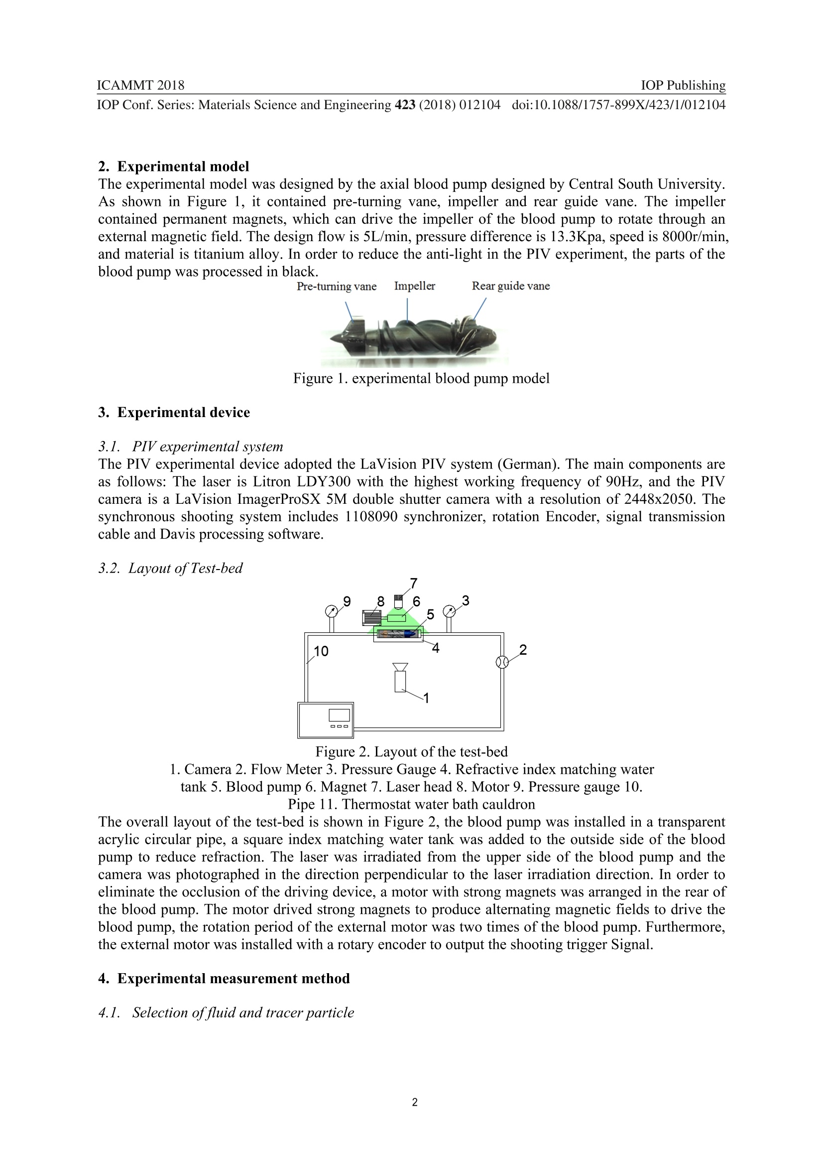
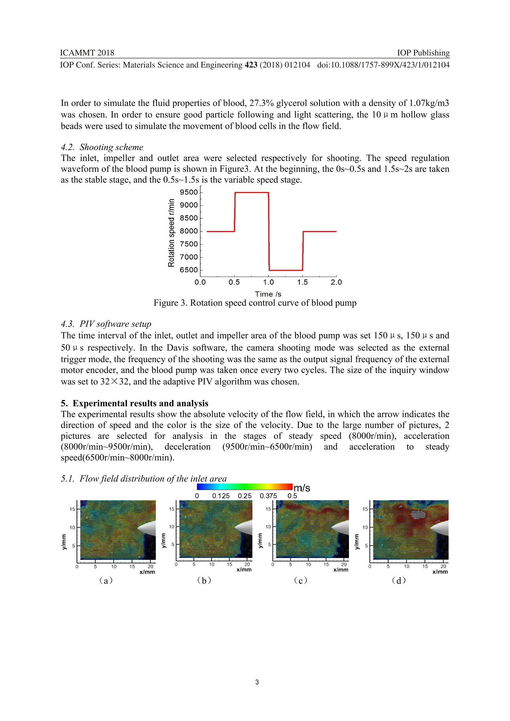
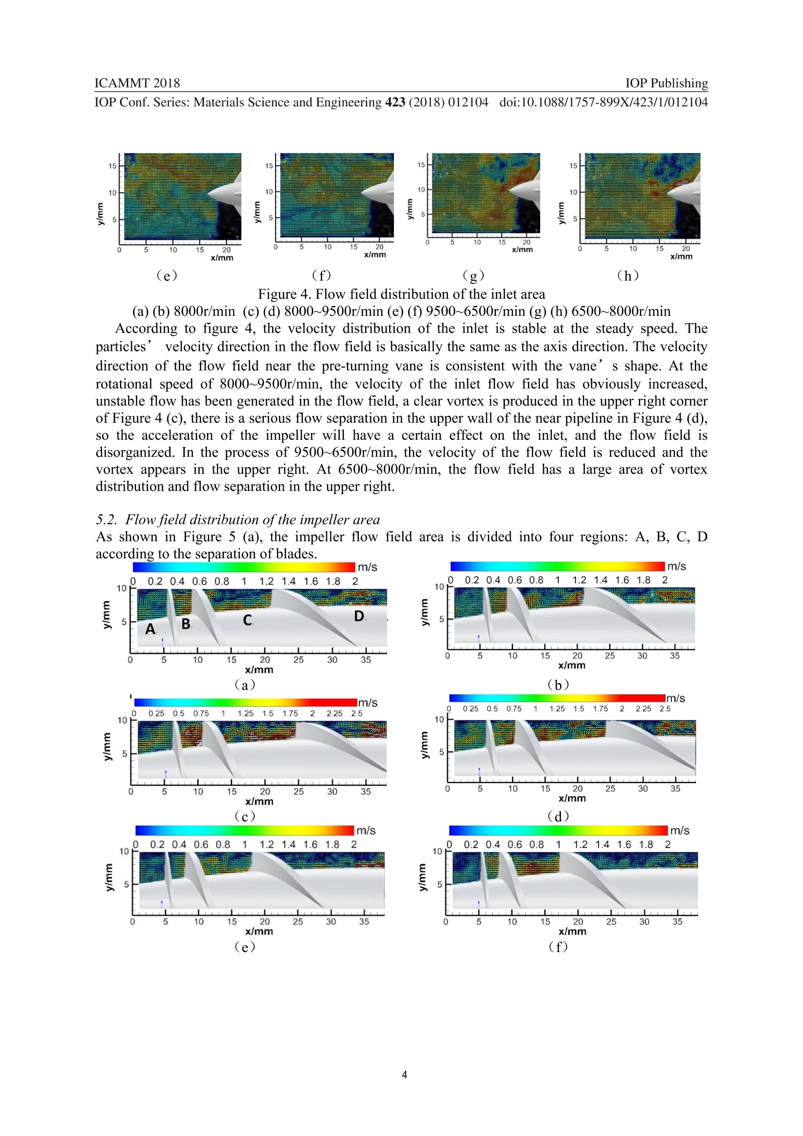
IOP Conference Series: Materials Science and Engineering IOP PublishingICAMMT 2018IOP Conf. Series: Materials Science and Engineering 423 (2018)012104doi:10.1088/1757-899X/423/1/012104 PAPER·OPEN ACCESS PIV Experimental Study of the Axial Flow Blood Pump's Internal FlowField Under Pulsatile Condition To cite this article: Shuai Wang et al 2018 IOP Conf. Ser.: Mater. Sci. Eng. 423 012104 TMIOP ebooks Bringing you innovative digital publishing with leading voicesto create your essential collection of books in STEM research. Start exploring the collection - download the first chapter ofevery title for free. PIV Experimental Study of the Axial Flow Blood Pump’sInternal Flow Field Under Pulsatile Condition Wang Shuai, Tan Jianping, Yu Zheqin, Xiao Zhiyong, Wu Weiqiang, Cheng lizhi School of Mechanical and Electrical Engineering, Central South University, Changsha410083, China E-mail: jptan@163.com Abstract. Taking the axial flow blood pump as the research object,we used the particle imagevelocimetry (PIV) to measure the flow distribution of inlet, outlet and impeller at the changingrotation speed. Effects of the acceleration and deceleration process on the change of internalflow field were compared and analyzed. The experimental results show that the flow field ofinlet and outlet area of the blood pump is stable at the constant working speed, but the vortexand reflux exist in the impeller area. However, acceleration of the impeller increases the flowfield’s volocity and disturbance. Deceleration of the impeller rotation speed reduces the flowvelocity, and the flow state of overall flow field is relatively stable. Design of the pulsatileblood pump should be optimized in order to reduce the occurrence of hemolysis in the processof acceleration and deceleration. 1. Introduction At present, there are more than twenty million of the heart failure patients worldwide, and it is nowrising rapidly because of the aging of the population2. The treatment of heart support through theimplantation of blood pump artificial heart has become the best treatment for the lack of heart donor.The widely used blood pump is the second generation and the third generation blood pump. Whichworking principle is to generate continuous output flow by rotating the impeller. However,commercially blood pumps use constant speed mode to provide continuous flow for the bodygenerally. With long-term continuous flow assisted, the human body can lead to impaired renalfunction 13-4], ischemic and hemorrhagic stroke [], vascular dysfunctiono], oxidative stressI, and thedigestive tract arteriovenous malformations] and aortic stiffness i19]ncreased. These adverse effectshave become one of the key problems that restrict the development of blood pumps. Based on the above problems, experts have proposed that the pulsation flow similar to the heart canbe generated by rapid and periodic changes in the speed of the blood pump, which causes the bloodpump to work at the non-design point, and the internal flow field will change violently, which willaffect the hemolysis performance of the blood pump. Therefore, it is necessary to study the internalflow field of the blood pump under pulsating condition, and analyze the effect of the variable speed onthe flow field. Chen Z 110] used CFD simulation to analyze the transient state of the axial flow pump andcentrifugal pump under the pulsating flow condition, and pointed out that the high hemolysis area mayappear in the interior of the pump. F Shu n used PIV to shoot the flow field of the centrifugal bloodpump in the pulsating mode, and analyzed the time-varying characteristics of the internal flow field.Wong, K, C and other 2] used PIV to rotate the blood pump in the pulsating condition of5 differentgeometric shapes at the outlet of the flow field. ( Published under licence by IOP Publishing Ltd ) 2. Experimental model The experimental model was designed by the axial blood pump designed by Central South University.As shown in Figure 1, it contained pre-turning vane, impeller and rear guide vane. The impellercontained permanent magnets, which can drive the impeller of the blood pump to rotate through anexternal magnetic field. The design flow is 5L/min, pressure difference is 13.3Kpa, speed is 8000r/min,and material is titanium alloy. In order to reduce the anti-light in the PIV experiment, the parts of theblood pump was processed in black. Figure 1. experimental blood pump model 3. Experimental device 3.1. PIV experimental system The PIV experimental device adopted the LaVision PIV system (German). The main components areas follows: The laser is Litron LDY300 with the highest working frequency of 90Hz, and the PIVcamera is a LaVision ImagerProSX 5M double shutter camera with a resolution of 2448x2050. Thesynchronous shooting system includes 1108090 synchronizer, rotation Encoder, signal transmissioncable and Davis processing software. 3.2. Layout of Test-bed Figure 2. Layout of the test-bed 1. Camera 2. Flow Meter 3. Pressure Gauge 4. Refractive index matching watertank 5. Blood pump 6. Magnet 7. Laser head 8. Motor 9. Pressure gauge 10. Pipe 11. Thermostat water bath cauldron The overall layout of the test-bed is shown in Figure 2, the blood pump was installed in a transparentacrylic circular pipe, a square index matching water tank was added to the outside side of the bloodpump to reduce refraction. The laser was irradiated from the upper side of the blood pump and thecamera was photographed in the direction perpendicular to the laser irradiation direction. In order toeliminate the occlusion of the driving device, a motor with strong magnets was arranged in the rear ofthe blood pump. The motor drived strong magnets to produce alternating magnetic fields to drive theblood pump, the rotation period of the external motor was two times of the blood pump. Furthermore,the external motor was installed with a rotary encoder to output the shooting trigger Signal. 4. Experimental measurement method 4.1. Selection of fluid and tracer particle In order to simulate the fluid properties of blood, 27.3% glycerol solution with a density of 1.07kg/m3was chosen. In order to ensure good particle following and light scattering, the 10 u m hollow glassbeads were used to simulate the movement of blood cells in the flow field. 4.2. Shooting scheme The inlet, impeller and outlet area were selected respectively for shooting. The speed regulationwaveform of the blood pump is shown in Figure3. At the beginning, the 0s~0.5s and 1.5s~2s are takenas the stable stage, and the 0.5s~1.5s is the variable speed stage. Figure 3. Rotation speed control curve of blood pump 4.3. PIV software setup The time interval of the inlet, outlet and impeller area of the blood pump was set 150 us, 150 us and50 us respectively. In the Davis software, the camera shooting mode was selected as the externaltrigger mode, the frequency of the shooting was the same as the output signal frequency of the externalmotor encoder, and the blood pump was taken once every two cycles. The size of the inquiry windowwas set to 32×32, and the adaptive PIV algorithm was chosen. 5. Experimental results and analysis The experimental results show the absolute velocity of the flow field, in which the arrow indicates thedirection of speed and the color is the size of the velocity. Due to the large number of pictures, 2picturesS:are selected for analysisintthe stages of steadyspeed:d(8000r/min).). acceleration(8000r/min~9500r/min). deceleration (9500r/min~6500r/min) and acceleration to steadyspeed(6500r/min~8000r/min). 5.1. Flow field distribution of the inlet area EE (e) (f) (g) (h) Figure 4. Flow field distribution ofthe inlet area (a) (b) 8000r/min (c)(d) 8000~9500r/min (e) (f) 9500~6500r/min (g) (h) 6500~8000r/minAccording to figure 4, the velocity distribution of the inlet is stable at the steady speed. Theparticles’ velocity direction in the flow field is basically the same as the axis direction. The velocitydirection of the flow field near the pre-turning vane is consistent with the vane’s shape. At therotational speed of 8000~9500r/min, the velocity of the inlet flow field has obviously increased,unstable flow has been generated in the flow field, a clear vortex is produced in the upper right cornerof Figure 4 (C), there is a serious flow separation in the upper wall of the near pipeline in Figure 4 (d),so the acceleration of the impeller will have a certain effect on the inlet, and the flow field isdisorganized. In the process of 9500~6500r/min, the velocity of the flow field is reduced and thevortex appears in the upper right. At 6500~8000r/min, the flow field has a large area of vortexdistribution and flow separation in the upper right. 5.2. Flow field distribution of the impeller area As shown in Figure 5 (a), the impeller flow field area is divided into four regions: A, B, C, Daccording to the separation of blades. IOP Conf. Series: Materials Science and Engineering 423 (2018) 012104doi:10.1088/1757-899X/423/1/012104 Figure 5. Flow field distribution of the impeller area (a) (b) 8000r/min (c)(d) 8000~9500r/min (e)(f) 9500~6500r/min (g)(h) 6500~8000r/min As shown in Figure 5, the velocity of A, B and C increases in turn at the stable speed of 8000r/min.The distribution of the flow field in the A, B and C region is more stable. Due to the hindrance effectof the rear guide vane, the velocity of D region decreases, and the unstable flow state such as refluxand vortex appear. Compared with the stable state, in the process of 8000~9500r/min, the velocity ofthe C region near the hub increases, the phenomenon of flow separation increases. The reflux stillexists in the D region, the velocity of the flow field increases with the increase of the speed. In theprocess of 9500~6500r/min, the flow field of A, B and C is basically stable and the velocity directionis parallel to the axis. The velocity of the flow field in the D region is smaller, but there is a backflowphenomenon at the outlet and the number of the vortices increases. In the process of 6500~8000r/min,the distribution of flow field is similar to the 8000~9500r/min stage, the flow field is disturbed in the Cregion, there is a phenomenon of reflux and flow separation at the outlet of the D region. 5.3. Flow field distribution ofthe outlet area lm/s Figure 6. Flow field distribution of the outlet area (a)(b) 8000r/min (c) (d) 8000~9500r/min (e)(f) 9500~6500r/min (g) (h) 6500~8000r/min As shown in Figure 6, at the stable speed of 8000r/min, the streamline at the edge of the rear guidevane is basically consistent with the outline of the rear guide vane, and a high speed belt appears at theupper wall and center of the outlet area. In the process of 8000~9500r/min, speed of the flow centerincreases, the flow separation and vortex appear at the top wall of the rear guide vane, the number ofvortices in the flow field increases, also the disturbance of the flow field increases. During thedeceleration process of 9500~6500r/min, the overall velocity in the flow field decreases, and the flowaround the rear guide vane is basically the same as the external contour. In the process of 6500~8000r/min, the overall velocity distribution increases, but a larger vortex appears above the rearguide vane. 6. Conclusion (1) At the stable speed, the flow field in the inlet area of the blood pump is stable, but the vortex andreflux exist in the region of the outlet of the impeller, which is caused by the obstruction of the rearguide blade. (2) During the acceleration of blood pump, vortex appears above the leading edge of the bloodpump. The D region of impeller shows obvious separation of flow, increase of vortex number andreflux velocity. The phenomenon of flow separation and vortex also appears in the outlet area. Themain reason is that the acceleration of impeller is large and the Reynolds number of the flow fieldincreases rapidly. Therefore, the unstable flow state of the flow is aggravated. (3) In the process of deceleration, the velocity of the inlet, impeller and outlet decreases, the overallflow state is more stable than the accelerated process, but vortexes exist at the outlet of the impellerarea. (4) In the process of variable speed, the Reynolds number inside the flow field changes rapidly, thedisturbance of the internal flow field increases obviously in the process of acceleration, which wilinevitably have a bad effect on the hemolytic performance of the blood pump. Therefore, the structureof blood pump should be optimized according to the flow field distribution in the speed changeprocess, so as to reduce the production of hemolysis during the process of the speed change. Acknowledgments This work was supported by National Natural Science Foundation of China (Grant No. 51475477,31670999). ( References ) [1] Bui, A. L., Horwich, T. B., & Fonarow, G. C. (2011). Epidemiology and risk profile of heartfailure. Nature Reviews Cardiology, 8(1), 30-41. ( [2] Smolina, K., Wright, F. L . , Rayner, M., & Goldacre, M. J.(2 0 12). Determinants of the declin e in mortality from acute myocardial i nfarction in england between 2002 a n d 2010: li n kednational database study. Bmj, 344(jan252), d8059. ) [3 Borgi, J., Tsiouris, A., Hodari, A., Cogan, C. M., Paone, G., & Morgan, J. A. (2013)Significance of postoperative acute renal failure after continuous-flow left ventricular assisdevice implantation. Annals of Thoracic Surgery,95(1), 163. Patel, A. M., Adeseun, G. A., Ahmed, I., Mitter,N., Rame, J. E., & Rudnick,M. R. (2013).Renal failure in patients with left ventricular assist devices. Clinical Journal of the AmericanSociety of Nephrology Cjasn, 8(3), 484. [5] Starling RC; Moazami N; Silvestry SC; Ewald G; Rogers JG;Milano CA; Rame JE; Acker MA;Blackstone EH; Ehrlinger J; Thuita L; Mountis MM; Soltesz EG; Lytle BW; Smedira NG.(2014). Increase in left ventricular assist device thrombosis. New England Journal ofMedicine, 370(1), 33-40. [6] Gambillara, V., Thacher, T., Silacci, P., & Stergiopulos, N. (2008). Effects of reduced cyclic.stretch on vascular smooth muscle cell function of pig carotids perfused ex vivo. Journal ofBiomechanics, 39(4), S279-S279. [77] Thacher, T., Gambillara, V., Da, S. R., Silacci, P., & Stergiopulos,N. (2010). Reduced cyclicstretch, endothelial dysfunction, and oxidative stress: an ex vivo model. CardiovascularPathology, 19(4), e91-e98. [8] Demirozu, Z. T., Radovancevic, R., Hochman, L. F., Gregoric, I. D., Letsou, G. V., & Kar, B..et al. (2011). Arteriovenous malformation and gastrointestinal bleeding in patients with theheartmate ii left ventricular assist device. Journal of Heart & Lung Transplantation theOfficial Publication of the International Society for Heart Transplantation, 30(8), 849-853. IOP Conf.Series: Materials Science and Engineering 423 (2018)012104doi:10.1088/1757-899X/423/1/012104 ( [9] Nassif, M. E ., Tibrewala, A ., Raymer, D . S . , Andruska, A., Novak, E. , & Vader, J. M ., et al.(2015). S ystolic blood pressure on discharge after left ven t ricular assist dev i ce inse r tion is.associated with subsequent stroke. Journal of Heart & Lung Transplantation, 34(4), 503-508. ) [10] Chen, Z., Jena,S. K., Giridharan, G. A., Koenig, S. C., Slaughter, M. S., & Griffith,B. P., et al..(2017). Flow features and device-induced blood trauma in cf-vads under a pulsatile bloodflow condition: a cfd comparative study. International Journal for Numerical Methods inBiomedical Engineering, 34(2),e2924. [11]Shu, F., Vandenberghe, S., Brackett, J., & Antaki, J. F. (2015). Classification of unsteady flowpatterns in a rotodynamic blood pump: introduction of non-dimensional regime mapCardiovascular Engineering & Technology,6(3), 230-241. [12]Wong, K. C., Buisen, M., Benzinger, C., Gang, R., Bezema, M., & Greatrex, N., et al. (2014)Effect of rotary blood pump pulsatility on potential parameters of blood compatibility andthrombosis in inflow cannula tips. International Journal of Artificial Organs, 37(12),875-87. This content was downloaded from IP address on at Taking the axial flow blood pump as the research object, we used the particle imagevelocimetry (PIV) to measure the flow distribution of inlet, outlet and impeller at the changingrotation speed. Effects of the acceleration and deceleration process on the change of internalflow field were compared and analyzed. The experimental results show that the flow field ofinlet and outlet area of the blood pump is stable at the constant working speed, but the vortexand reflux exist in the impeller area. However, acceleration of the impeller increases the flowfield’s volocity and disturbance. Deceleration of the impeller rotation speed reduces the flowvelocity, and the flow state of overall flow field is relatively stable. Design of the pulsatileblood pump should be optimized in order to reduce the occurrence of hemolysis in the process of acceleration and deceleration.
确定


还剩6页未读,是否继续阅读?

产品配置单


北京欧兰科技发展有限公司为您提供《轴流血液泵中内部流场速度场检测方案(CCD相机)》,该方案主要用于全血/血清/血浆中内部流场速度场检测,参考标准--,《轴流血液泵中内部流场速度场检测方案(CCD相机)》用到的仪器有德国LaVision PIV/PLIF粒子成像测速场仪、LaVision DaVis 智能成像软件平台
推荐专场


相关方案
更多
该厂商其他方案
更多