


方案详情
文
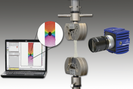
提出了一种新颖的基于结构化光照明的方法,基于数字图像相关(DIC)原理实现用一台相机进行3维表明形貌,形变以及应变测量。
方案详情

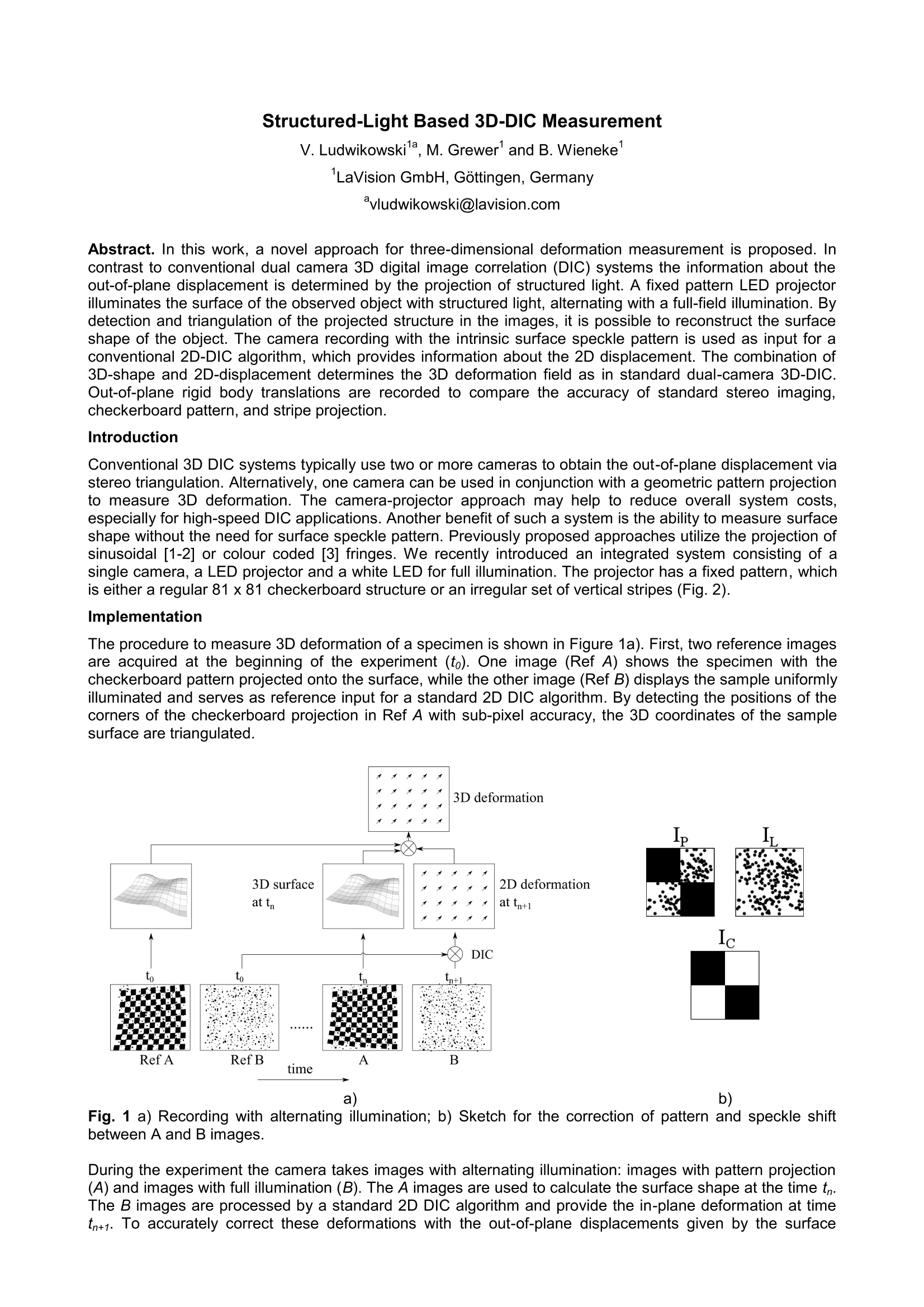
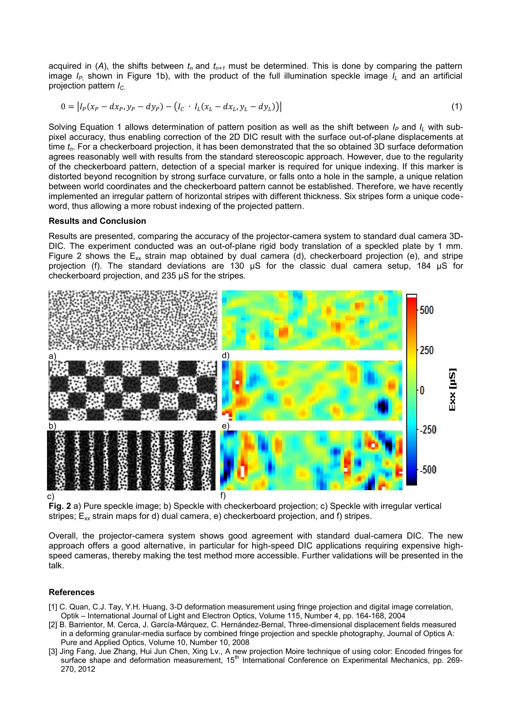
Structured-Light Based 3D-DIC Measurement V. Ludwikowski, M. Grewer and B. Wieneke LaVision GmbH, Gottingen, Germanyvludwikowski@lavision.com Abstract. In this work, a novel approach for three-dimensional deformation measurement is proposed. Incontrast to conventional dual camera 3D digital image correlation (DIC) systems the information about theout-of-plane displacement is determined by the projection of structured light. A fixed pattern LED projectorilluminates the surface of the observed object with structured light, alternating with a full-field illumination. Bydetection and triangulation of the projected structure in the images, it is possible to reconstruct the surfaceshape of the object. The camera recording with the intrinsic surface speckle pattern is used as input for aconventional 2D-DIC algorithm, which provides information about the 2D displacement. The combination of3D-shape and 2D-displacement determines the 3D deformation field as in standard dual-camera 3D-DIC.Out-of-plane rigid body translations are recorded to compare the accuracy of standard stereo imaging,checkerboard pattern, and stripe projection. Introduction Conventional 3D DIC systems typically use two or more cameras to obtain the out-of-plane displacement viastereo triangulation. Alternatively, one camera can be used in conjunction with a geometric pattern projectionto measure 3D deformation. The camera-projector approach may help to reduce overall system costs,especially for high-speed DIC applications. Another benefit of such a system is the ability to measure surfaceshape without the need for surfacespeckle pattern. Previously proposed approaches utilize the projection ofsinusoidal [1-2] or colour coded [3] fringes. We recently introduced an integrated system consisting of asingle camera, a LED projector and a white LED for full illumination. The projector has a fixed pattern, whichis either a regular 81 x 81 checkerboard structure or an irregular set of vertical stripes (Fig.2). Implementation The procedure to measure 3D deformation of a specimen is shown in Figure 1a). First, two reference imagesare acquired at the beginning of the experiment (to). One image (Ref A) shows the specimen with thecheckerboard pattern projected onto the surface, while the other image (Ref B) displays the sample uniformlyilluminated and serves as reference input for a standard 2D DIC algorithm. By detecting the positions of thecorners of the checkerboard projection in Ref A with sub-pixel accuracy, the 3D coordinates of the samplesurface are triangulated. a) b) Fig. 1 a) Recording with alternating illumination; b) Sketch for the correction of pattern and speckle shiftbetween A and B images. During the experiment the camera takes images with alternating illumination: images with pattern projection(A) and images with full illumination (B). The A images are used to calculate the surface shape at the time t.The B images are processed by a standard 2D DIC algorithm and provide the in-plane deformation at timetn+1. To accurately correct these deformations with the out-of-plane displacements given by the surface acquired in (A), the shifts between t and tn+1 must be determined. This is done by comparing the patternimage lp, shown in Figure 1b), with the product of the full illumination speckle image l and an artificialprojection pattern lc. Solving Equation 1 allows determination of pattern position as well as the shift between lp and / with sub-pixel accuracy, thus enabling correction of the 2D DIC result with the surface out-of-plane displacements attime t. For a checkerboard projection, it has been demonstrated that the so obtained 3D surface deformationagrees reasonably well with results from the standard stereoscopic approach.However, due to the regularityof the checkerboard pattern, detection of a special marker is required for unique indexing. If this marker isdistorted beyond recognition by strong surface curvature, or falls onto a hole in the sample, a unique relationbetween world coordinates and the checkerboard pattern cannot be established. Therefore, we have recentlyimplemented an irregular pattern of horizontal stripes with different thickness. Six stripes form a unique code-word, thus allowing a more robust indexing of the projected pattern. Results and Conclusion Results are presented, comparing the accuracy of the projector-camera system to standard dual camera 3D-DIC. The experiment conducted was an out-of-plane rigid body translation of a speckled plate by 1 mm.Figure 2 shows the Exx strain map obtained by dual camera (d), checkerboard projection (e), and stripeprojection (f). The standard deviations are 130 pS for the classic dual camera setup, 184 puS forcheckerboard projection, and 235 pS for the stripes. Fig. 2 a) Pure speckle image; b) Speckle with checkerboard projection; c) Speckle with irregular verticalstripes; Exx strain maps for d) dual camera, e) checkerboard projection, and f) stripes. Overall, the projector-camera system shows good agreement with standard dual-camera DIC. The newapproach offers a good alternative, in particular for high-speed DIC applications requiring expensive high-speed cameras, thereby making the test method more accessible. Further validations will be presented in thetalk. References [1] C. Quan, C.J. Tay, Y.H. Huang, 3-D deformation measurement using fringe projection and digital image correlation,Optik -International Journal of Light and Electron Optics, Volume 115, Number 4, pp. 164-168, 2004 [2] B. Barrientor, M. Cerca, J. Garcia-Marquez, C. Hernandez-Bernal, Three-dimensional displacement fields measured ina deforming granular-media surface by combined fringe projection and speckle photography, Journal of Optics A:Pure and Applied Optics, Volume 10, Number 10, 2008 [3] Jing Fang,Jue Zhang, Hui Jun Chen, Xing Lv., A new projection Moire technique of using color: Encoded fringes forsurface shape and deformation measurement, 15" International Conference on Experimental Mechanics, pp. 269-270, 2012 In this work, a novel approach for three-dimensional deformation measurement is proposed. In contrast to conventional dual camera 3D digital image correlation (DIC) systems the information about the out-of-plane displacement is determined by the projection of structured light. A fixed pattern LED projector illuminates the surface of the observed object with structured light, alternating with a full-field illumination. By detection and triangulation of the projected structure in the images, it is possible to reconstruct the surface shape of the object. The camera recording with the intrinsic surface speckle pattern is used as input for a conventional 2D-DIC algorithm, which provides information about the 2D displacement. The combination of 3D-shape and 2D-displacement determines the 3D deformation field as in standard dual-camera 3D-DIC. Out-of-plane rigid body translations are recorded to compare the accuracy of standard stereo imaging, checkerboard pattern, and stripe projection.
确定
还剩1页未读,是否继续阅读?

产品配置单


北京欧兰科技发展有限公司为您提供《固体材料中形变、应变、形貌检测方案(其它无损检测仪器/设备)》,该方案主要用于其他中形变、应变、形貌检测,参考标准--,《固体材料中形变、应变、形貌检测方案(其它无损检测仪器/设备)》用到的仪器有LaVision StrainMaster材料应变形变成像测量系统、德国LaVision PIV/PLIF粒子成像测速场仪
推荐专场


相关方案
更多
该厂商其他方案
更多