


Injection processing of composite materials most often includes infiltration of a
thermoset resin into a multi-scale porous fabric. Controlling the fluid flow within the multiscale
fabric is essential for the quality of the final composite material, since the transport of
fluid between regions with different scales plays an important role in phenomena such as void
formation and filtration of particle doped resins.
In this work, the transient flow behaviour in dual scale porous media is investigated
with Micro Particle Image Velocimetry in order to enhance the knowledge and control of the
processing of multi-scale composites so that their quality can be improved. Experiments show
that the fluid transport between the two scales can be controlled by the injection velocity.
Validation of the measured velocity fields furthermore shows excellent agreement with
theory.
方案详情

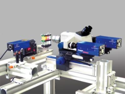
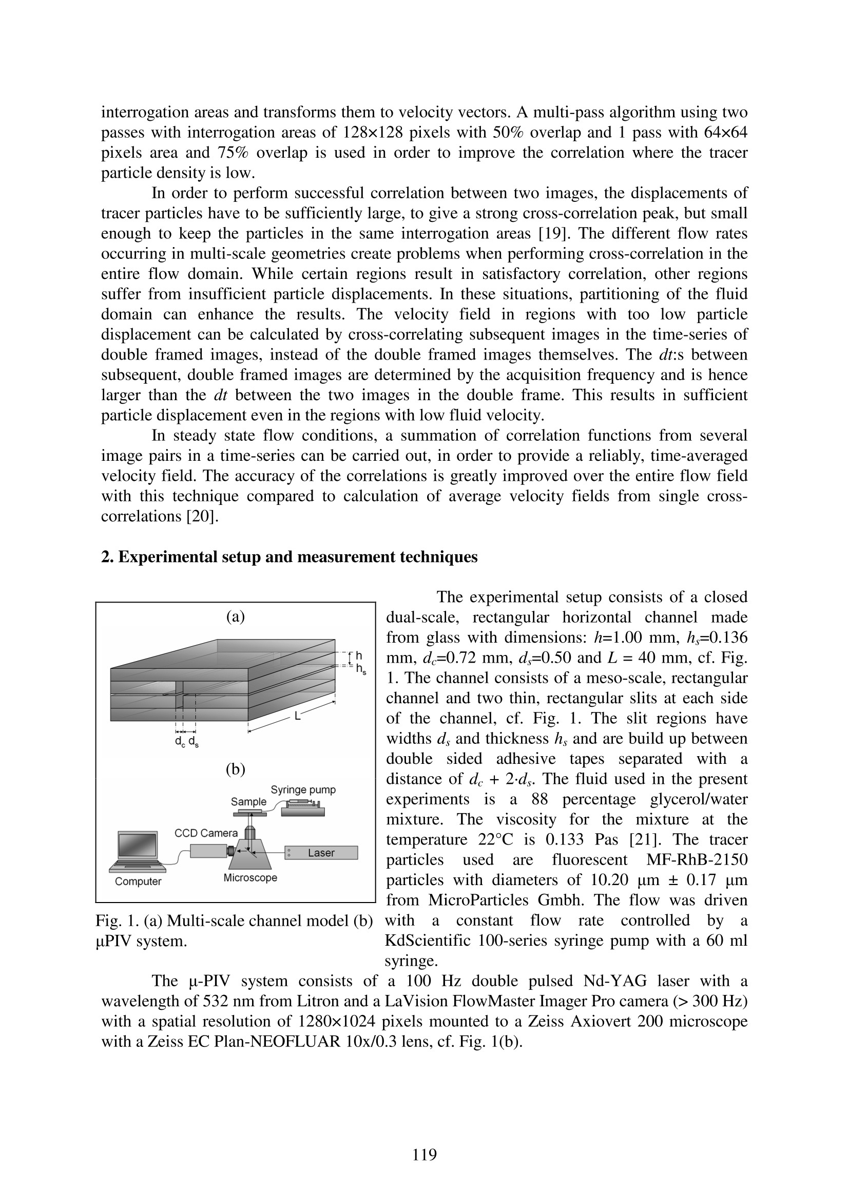
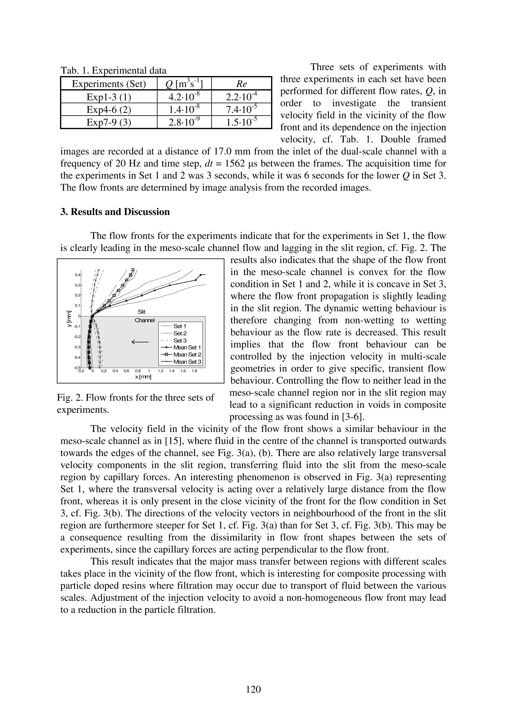
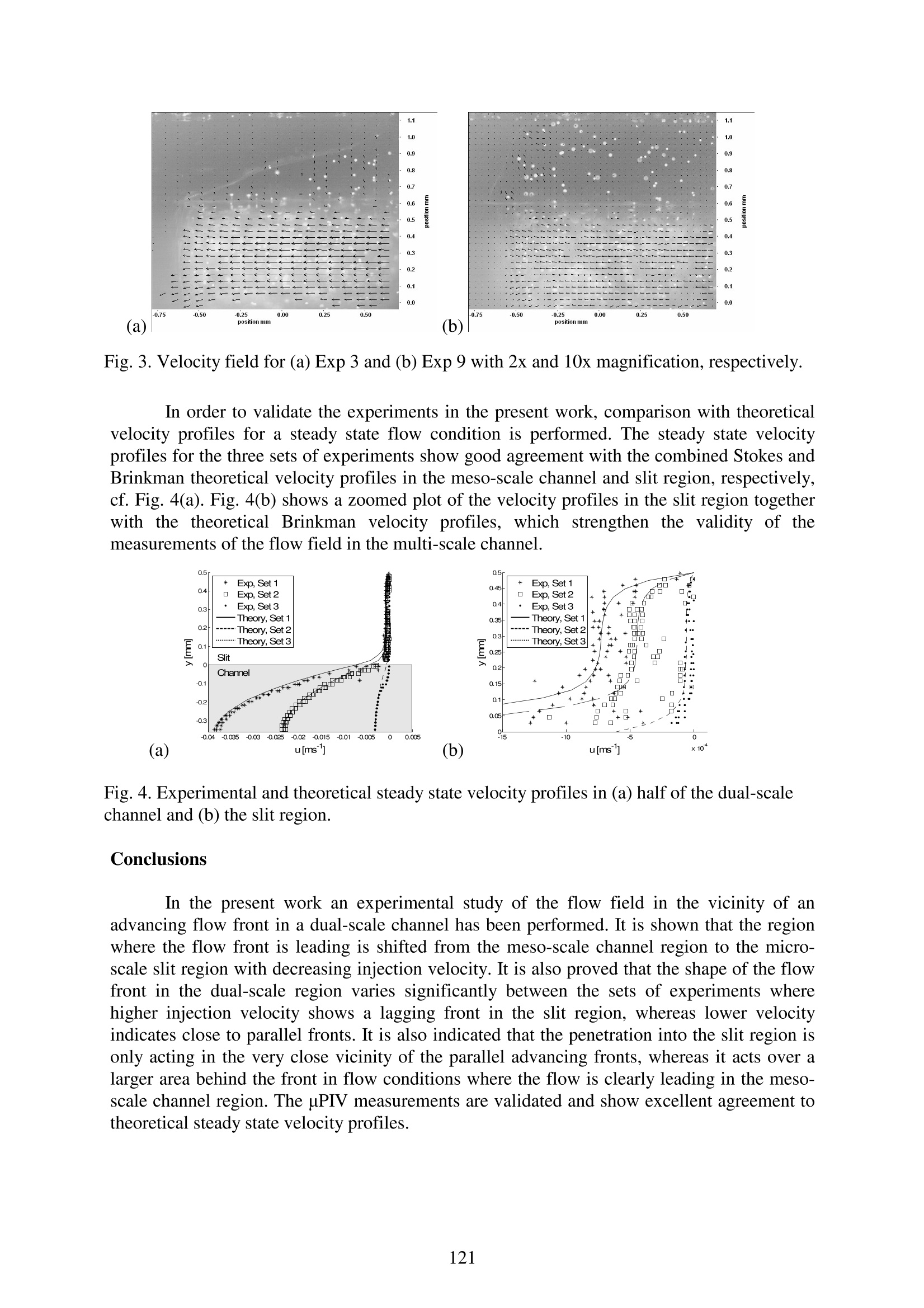
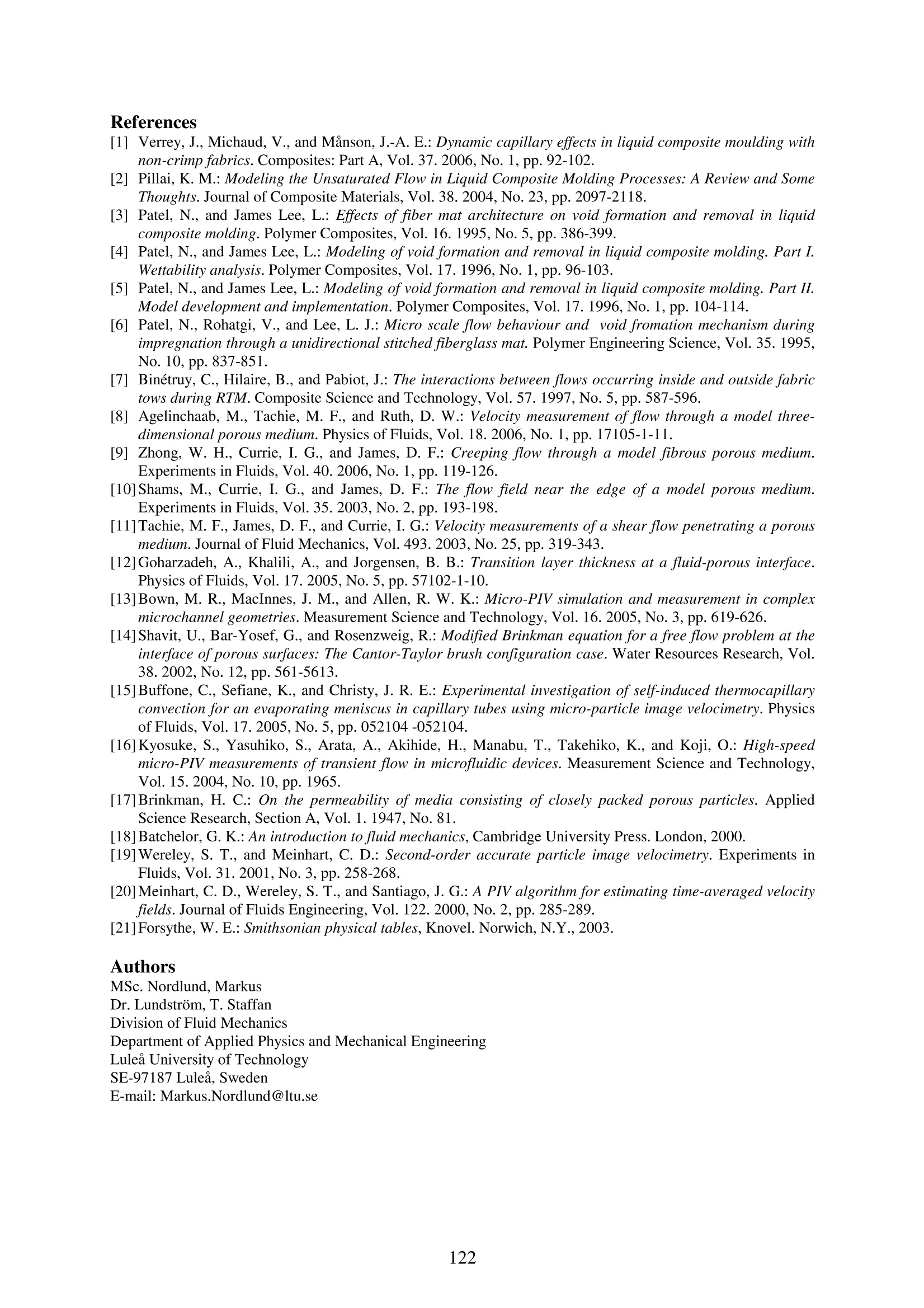
International Scientific ColloquiumModelling for Material ProcessingRiga, June 8-9, 2006 Investigation of Transient Flow Behaviour in Dual-scale PorousMedia with Micro Particle Image Velocimetry M. Nordlund,T.S. Lundstrom Abstract Injection processing of composite materials most often includes infiltration of athermoset resin into a multi-scale porous fabric. Controlling the fluid flow within the multi-scale fabric is essential for the quality of the final composite material, since the transport offluid between regions with different scales plays an important role in phenomena such as voidformation and filtration of particle doped resins. In this work, the transient flow behaviour in dual scale porous media is investigatedwith Micro Particle Image Velocimetry in order to enhance the knowledge and control of theprocessing of multi-scale composites so that their quality can be improved. Experiments showthat the fluid transport between the two scales can be controlled by the injection velocity.Validation of the measured velocity fields furthermore shows excellent agreement withtheory. Introduction Manufacturingof fibre reinforced compositematerialsalwaysincludes animpregnation stage, where resin is allowed to flow into a geometry. During impregnation,air/fibre interfaces are replaced by resin/fibre interfaces at the flow front. A pressuredifference is present over the flow front due to the difference in surface tension between theresin and the air. This pressure difference, called capillary pressure drop can either enhance orwork against the filling depending on the curvature of the interface surface [1]. A multi-scalegeometry, built from fibre bundles, results in an inhomogeneous wetting of the fabric. Thisimplies that there will be non-uniform flow front propagation in the fabric, since the flow canbe leading either in the micro-scale fibre bundles or in the meso-scale inter-bundle channelsdepending on the dynamic wetting behaviour of the fluid in combination with the injectionvelocity [2]. In [3-6] it is shown that these effects play important roles in void formationduring low pressure injections. An optimal resin infiltration velocity was found in [4;5]which reduces void formation. The optimal state implies that neither the micro-scale flow inthe fibre bundles nor the meso-scale flow in the inter-bundle spacings is leading. Below thisvalue, where the capillary effects are dominant over the viscous effects, the flow is leading inthe fibre bundles and can entrap voids in the meso-scale regions and the other way aroundwhen the flow is leading in the meso-scale regions. The lack of capillary effects in saturatedflow conditions results in that the flow in the meso-scale geometry is dominating over themicro-scale flow [7]. Micro Particle Image Velocimetry (uPIV) is a measurement technique to determinevelocity fields in micro-scale geometries. This was exemplified for flows through porousmedia in [8; 9], where the measured two-dimensional flows through hexagonal arrangementof cylindrical rods showed good agreement with existing theory. The problem of multi-scale porosity was furthermore studied in [8; 10;11], where the flow in the transition zone betweenthe porous medium and the meso-scale geometry were investigated. In [12], reflective indexmatched uPIV showed that the transition layer between the two different porosities is of theorder of the fibre diameter of the porous media instead of √K, where K is the permeability,as predicted by the theory for steady state flow conditions. The result is furthermore supportedby investigations presented in [10; 11]. Complex multi-scale geometries rather that structuredporous media were studied in [13] in order to develop and validate a theoretical modeldescribing the dual-scale flow and in [14] to investigate the systematic error produced by theinterrogation volumes in the uPIV method, respectively. Transient micro-scale flow has been studied in [15], where refractive index matcheduPIV was used to measure the velocity field in the vicinity of a meniscus in a capillary tube. Itwas shown that symmetrical vorticies are produced behind the meniscus. Furthermore, ameasurement technique in order to study fast transient flow phenomena was developed usinghigh speed pPIV measurements in [16]. As discussed above, experimental investigations of the steady state flow conditions inthe interface region of multi-scale porosities has been presented, but there is still a lack ofunderstanding of the transient velocity field and the mass transfer between regions of differentscales in the vicinity of a flow front in multi-scale porous media. This flow phenomenon,together with its implication to the processing stage of composite manufacturing, is thereforestudied in detail in the present work by the use of uPIV measurements. 1.Theory Steady state flow through a multi scale porous media, consisting of micro-scale andmeso-scale regions, experiences different flow conditions in different regions. In the micro-scale region, the flow can often be described using Brinkman equation [17]: where p is the pressure, u the velocity vector, u the viscosity and K the permeability, whereasthe meso-scale flow in the channel can be approximated by Stokes equation when inertia isnegligible [18] In thin, rectangular channels, the permeability can be calculated analytically by assumingStokes flow between two indefinitely large, parallel plates to be h/12, where h is thedistance between the plates. Matching Eqn:s (1.1) and (1.2), with boundary conditionspreserving continuity, results in an expression for the theoretical velocity profile, which willbe used to validate the experiments. uPIV is a technique for measuring velocity fields in microscopic fluid systems. Thetechnique is based on cross-correlation of double framed images with a short time differencedt, of illuminated, fluorescent tracer particles in the flow field. A double pulsed laser source,synchronized with a double framed CCD camera, is used for the recording of time series ofdouble framed images. Since the entire fluid domain is illuminated in uPIV, the measurementplane is set by the focal plane of the microscope. The velocity field is calculated by a cross-correlation algorithm based on Fast FourierTransform (FFT), which calculates the particle displacements between the two frames in small interrogation areas and transforms them to velocity vectors. A multi-pass algorithm using twopasses with interrogation areas of 128×128 pixels with 50% overlap and 1 pass with 64x64pixels area and 75% overlap is used in order to improve the correlation where the tracerparticle density is low. In order to perform successful correlation between two images, the displacements oftracer particles have to be sufficiently large, to give a strong cross-correlation peak, but smallenough to keep the particles in the same interrogation areas [19]. The different flow ratesoccurring in multi-scale geometries create problems when performing cross-correlation in theentire flow domain. While certain regions result in satisfactory correlation, other regionssuffer from insufficient particle displacements. In these situations, partitioning of the fluiddomain can enhance the results. The velocity field in regionswith too low particledisplacement can be calculated by cross-correlating subsequent images in the time-series ofdouble framed images, instead of the double framed images themselves. The dt:s betweensubsequent, double framed images are determined by the acquisition frequency and is hencelarger than the dt between the two images in the double frame. This results in sufficientparticle displacement even in the regions with low fluid velocity. In steady state flow conditions, a summation of correlation functions from severalimage pairs in a time-series can be carried out, in order to provide a reliably, time-averagedvelocity field. The accuracy of the correlations is greatly improved over the entire flow fieldwith this technique compared to calculation of average velocity fields from single cross-correlations 201. 2. Experimental setup and measurement techniques Fig.1. (a) Multi-scale channel model (b)uPIV system. The experimental setup consists of a closeddual-scale, rectangular horizontal channel madefrom glass with dimensions: h=1.00 mm, hs=0.136mm, d=0.72 mm, d=0.50 and L=40 mm, cf. Fig.1. The channel consists of a meso-scale, rectangularchannel and two thin, rectangular slits at each sideof the channel, cf. Fig. 1. The slit regions havewidths ds and thickness hs and are build up betweendouble sided adhesive tapessseparated w adistance of de +2·d. The fluid used in the presentexperimentsis a 88 percentage g;lycerol/watermixture..TThee viscosity for the mixture aattthetemperature 22°C is0.133 Pas[21]. The tracerparticles usedare fluorescent MF-RhB-2150particles with diameters of 10.20 um±0.17 umfrom MicroParticles Gmbh. The flow was drivenwithh a constantflowratee controlledby aKdScientific 100-series syringe pump with a 60 mlsyringe. The u-PIV system consists of a 100 Hz double pulsed Nd-YAG laser with awavelength of 532 nm from Litron and a LaVision FlowMaster Imager Pro camera (> 300 Hz)with a spatial resolution of 1280×1024 pixels mounted to a Zeiss Axiovert 200 microscopewith a Zeiss EC Plan-NEOFLUAR 10x/0.3 lens, cf. Fig. 1(b). Experiments (Set) 0 [m's Re Exp1-3 (1) 4.210-8 2.2.10-4 Exp4-6 (2) 1.410 7.410*-5 Exp7-9 (3) 2.8·10-9 1.5.10-5 Three sets of experiments withthree experiments in each set have beenperformed for different flow rates, Q, inordertooinvestigatethe transientvelocity field in the vicinity of the flowfront and its dependence on the injectionvelocity, cf. Tab. 1. Double framed images are recorded at a distance of 17.0 mm from the inlet of the dual-scale channel with afrequency of 20 Hz and time step, dt= 1562 us between the frames. The acquisition time forthe experiments in Set 1 and 2 was 3 seconds, while it was 6 seconds for the lower Q in Set 3.The flow fronts are determined by image analysis from the recorded images. 3. Results and Discussion The flow fronts for the experiments indicate that for the experiments in Set 1, the flow Fig. 2. Flow fronts for the three sets ofexperiments. is clearly leading in the meso-scale channel flow and lagging in the slit region, cf. Fig. 2. Theresults also indicates that the shape of the flow front0.4- in the meso-scale channel is convex for the flow0.3- condition in Set 1 and 2, while it is concave in Set 3,0.2- where the flow front propagation is slightly leading0.1-Slit in the slit region. The dynamic wetting behaviour isChannel therefore changing from non-wetting to wetting-Set 1-Set 2 behaviour as the flow rate is decreased. This result-0.2Set 3 t h a t t h e f l o w f r o n t -0.3be →Mean Set 1behaviour can-0.4--Mean Set 2 controlled by the injection velocity in multi-scale—Mean Set 382 0.2 0.4 0.60.8 1 1.2 1.4 1.61.8 geometries in order to give specific, transient flowx[mm] behaviour. Controlling the flow to neither lead in themeso-scale channel region nor in the slit region maylead to a significant reduction in voids in compositeprocessing as was found in [3-6]. The velocity field in the vicinity of the flow front shows a similar behaviour in themeso-scale channel as in [15], where fluid in the centre of the channel is transported outwardstowards the edges of the channel, see Fig. 3(a), (b). There are also relatively large transversalvelocity components in the slit region, transferring fluid into the slit from the meso-scaleregion by capillary forces. An interesting phenomenon is observed in Fig. 3(a) representingSet 1, where the transversal velocity is acting over a relatively large distance from the flowfront, whereas it is only present in the close vicinity of the front for the flow condition in Set3, cf. Fig. 3(b). The directions of the velocity vectors in neighbourhood of the front in the slitregion are furthermore steeper for Set 1, cf. Fig. 3(a) than for Set3, cf. Fig. 3(b). This may bea consequence resulting from the dissimilarity in flow front shapes between the sets ofexperiments, since the capillary forces are acting perpendicular to the flow front. This result indicates that the major mass transfer between regions with different scalestakes place in the vicinity of the flow front, which is interesting for composite processing withparticle doped resins where filtration may occur due to transport of fluid between the variousscales. Adjustment of the injection velocity to avoid a non-homogeneous flow front may leadto a reduction in the particle filtration. Fig. 3. Velocity field for (a) Exp 3 and (b)Exp 9 with 2x and 10x magnification, respectively. In order to validate the experiments in the present work, comparison with theoreticalvelocity profiles for a steady state flow condition is performed. The steady state velocityprofiles for the three sets of experiments show good agreement with the combined Stokes andBrinkman theoretical velocity profiles in the meso-scale channel and slit region, respectively,cf. Fig. 4(a). Fig.4(b) shows a zoomed plot of the velocity profiles in the slit region togetherwith the theoretical Brinkman velocity profiles, which strengthen the validity of themeasurements of the flow field in the multi-scale channel. (a) Fig. 4. Experimental and theoretical steady state velocity profiles in (a) half of the dual-scalechannel and (b) the slit region. Conclusions In the present work an experimental study of the flow field in the vicinity of anadvancing flow front in a dual-scale channel has been performed. It is shown that the regionwhere the flow front is leading is shifted from the meso-scale channel region to the micro-scale slit region with decreasing injection velocity. It is also proved that the shape of the flowfront in the dual-scale region varies significantly between the sets of experiments wherehigher injection velocity shows a lagging front in the slit region, whereas lower velocityindicates close to parallel fronts. It is also indicated that the penetration into the slit region isonly acting in the very close vicinity of the parallel advancing fronts, whereas it acts over alarger area behind the front in flow conditions where the flow is clearly leading in the meso-scale channel region. The uPIV measurements are validated and show excellent agreement totheoretical steady state velocity profiles. ( References ) [1] Verrey, J., Michaud, V., and Manson, J.-A. E.:Dynamic capillary effects in liquid composite moulding withnon-crimp fabrics. Composites: Part A, Vol.37.2006,No. 1, pp. 92-102. [2] Pillai, K. M.: Modeling the Unsaturated Flow in Liquid Composite Molding Processes: A Review and SomeThoughts.Journal of Composite Materials, Vol. 38. 2004, No. 23, pp. 2097-2118. [3] Patel, N., and James Lee, L.: Effects of fiber mat architecture on void formation and removal in liquidcomposite molding. Polymer Composites, Vol. 16.1995, No.5,pp.386-399. .[4] Patel, N., and James Lee, L.: Modeling ofvoid formation and removal in liquid composite molding. Part I.Wettability analysis. Polymer Composites, Vol.17. 1996,No. 1,pp. 96-103. [5] Patel, N., and James Lee, L.:Modeling ofvoid formation and removal in liquid composite molding. Part II.Model development and implementation. Polymer Composites, Vol. 17. 1996, No. 1, pp.104-114. [6] Patel, N., Rohatgi, V., and Lee, L. J.: Micro scale flow behaviour and void fromation mechanism duringimpregnation through a unidirectional stitched fiberglass mat. Polymer Engineering Science, Vol. 35. 1995,No. 10, pp. 837-851. ( [7] B inetruy, C . , H i laire, B., and Pabiot, J.: The interactions be t ween flows occurring insid e and o u tside fabric tows during RTM. Composite S c ience and Technology,Vol. 57. 1997,No.5,pp. 587-596. ) ( [8] Agelinchaab, M ., Tachie, M. F . , and R u th, D . W . : Velocity measurement of flow through a m o d e l three-dimensional porous medium. Physics of Fluids, Vol. 18. 2006, No. 1, p p. 17105-1-11. ) ( [9] Zhong, W . H., Currie, I. G., and James, D. F.: Creeping flow through a model f ibrous porous medium. E xperiments in F l uids, Vol. 40. 2006, No. 1, pp. 119-126. ) ( [10] Shams, M., Currie , I. G., and James, D. F. : The flow field near the edge of a mode l porous medium E xperiments i n Fluids, Vol. 35. 2003, No.2, pp. 1 93-198. ) ( [11]Tachie,M. F . , James, D. F., and C urrie, I. G.: Velocity measurements ofa shear flow penetrating a porous m edium. J o urnal of Fluid Mechanics, V ol. 493.2003,No. 25,pp.319 - 343. ) ( [12] Goharzadeh, A., Khalili, A., and J orgensen, B. B.: Transition layer thickness at a fluid-porous interface.Physics of Fluids, Vol. 17.2005, No.5, pp. 57102-1-10. ) ( [ 1 3]Bown, M . R., M a cInnes, J. M . , and Allen, R. W. K. : Mi c ro-PIV sim u lation and measurement in co m plexmicrochannel geometries. Measurement Science and T echnology, Vol. 1 6. 2005, No. 3 , pp. 619-626. ) ( [14] Shavit, U., Bar-Yosef, G., and Rosenzweig, R.: Modified Brinkman equation for a free flow problem at theinterface ofporous surfaces: The C a ntor-Taylor brush configuration case. Water Resources Research, Vol.38. 2002, No. 12, pp. 561-5613. ) ( [15]Buffone, C . , S e fiane, K., and Christy, J. R. E. : Ex p erimental inve s tigation of self-induced thermocapillaryconvection for an evaporating meniscus in capillary tubes using micro-particle image velocimetry. Physicsof Fluids, Vol.17.2005,No.5,pp. 052104-052104. ) ( [16]Kyosuke, S. , Y asuhiko, S . ,A rata, A ., Akihide, H.,Manabu, T., Takehiko, K . , and K o ji, O.: High-speedmicro-PIV m e asurements of transient flow in m i crofluidic devices. Measurement Sc i ence and Technology,Vol. 15. 2 004, No. 1 0 , pp. 1 965. ) ( [17] Brinkman, H . C .: On t h e p e rmeability of media co n sisting of closely p a cked po r ous particles. Applied Science Research, Section A, Vol. 1. 1 947, No. 8 1 . ) [18]Batchelor, G. K.: An introduction to fluid mechanics,Cambridge University Press. London, 2000. ( [19]Wereley, S. T . , a nd M einhart, C. D.: Second-order accurate particle image ve l ocimetry. Ex p eriments inFluids, Vol . 31.2001 , No.3,pp. 258-268. ) [20] Meinhart, C. D., Wereley, S. T., and Santiago, J. G.: A PIV algorithm for estimating time-averaged velocityfields. Journal of Fluids Engineering, Vol.122.2000, No.2, pp.285-289. [21]Forsythe,W. E.: Smithsonian physical tables, Knovel. Norwich,N.Y., 2003. Authors MSc. Nordlund, Markus Dr. Lundstrom, T. Staffan Division of Fluid Mechanics Department of Applied Physics and Mechanical Engineering Lulea University of Technology SE-97187 Lulea. Sweden E-mail: Markus.Nordlund@ltu.se
确定
还剩4页未读,是否继续阅读?

产品配置单

北京欧兰科技发展有限公司为您提供《多孔介质中双尺度瞬态流动行为的显微PIV研究检测方案(粒子图像测速)》,该方案主要用于其他中双尺度瞬态流动行为的显微PIV研究检测,参考标准--,《多孔介质中双尺度瞬态流动行为的显微PIV研究检测方案(粒子图像测速)》用到的仪器有显微粒子成像测速系统(Micro PIV)、PLIF平面激光诱导荧光火焰燃烧检测系统
推荐专场


相关方案
更多
该厂商其他方案
更多