


方案详情
文
We have studied the flow induced by a macroscopic spherical particle settling in a Laponite
suspension that exhibits a yield stress, thixotropy, and shear thinning. We show that the fluid
thixotropy or aging induces an increase with time of both the apparent yield stress and
shear-thinning properties but also a breaking of the flow fore-aft symmetry predicted in
Hershel-Bulkley fluids yield-stress, shear-thinning fluids with no thixotropy. We have also varied
the stress exerted by the particles on the fluid by using particles of different densities. Although the
stresses exerted by the particles are of the same order of magnitude, the velocity field presents
utterly different features: whereas the flow around the lighter particle shows a confinement similar
to the one observed in shear-thinning fluids, the wake of the heavier particle is characterized by an
upward motion of the fluid “negative wake”, whatever the fluid’s age. We compare the features of
this negative wake to the one observed in viscoelastic shear-thinning fluids polymeric or micelle
solutions. Although the flows around the two particles strongly differ, their settling behaviors
display no apparent difference which constitutes an intriguing result and evidences the complexity
of the dependence of the drag factor on flow field.
方案详情

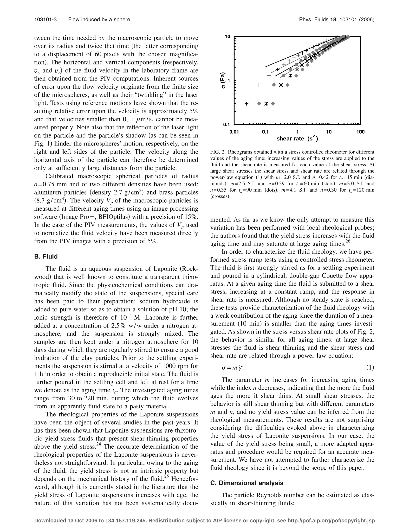
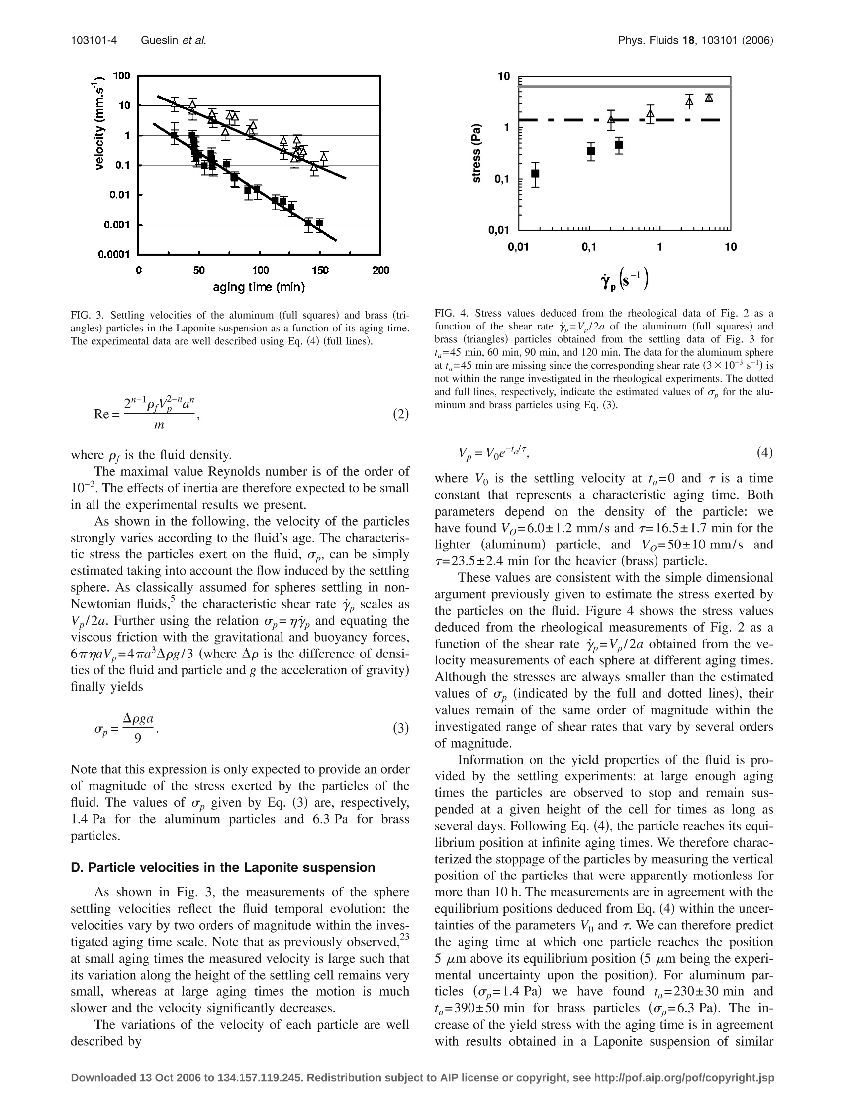
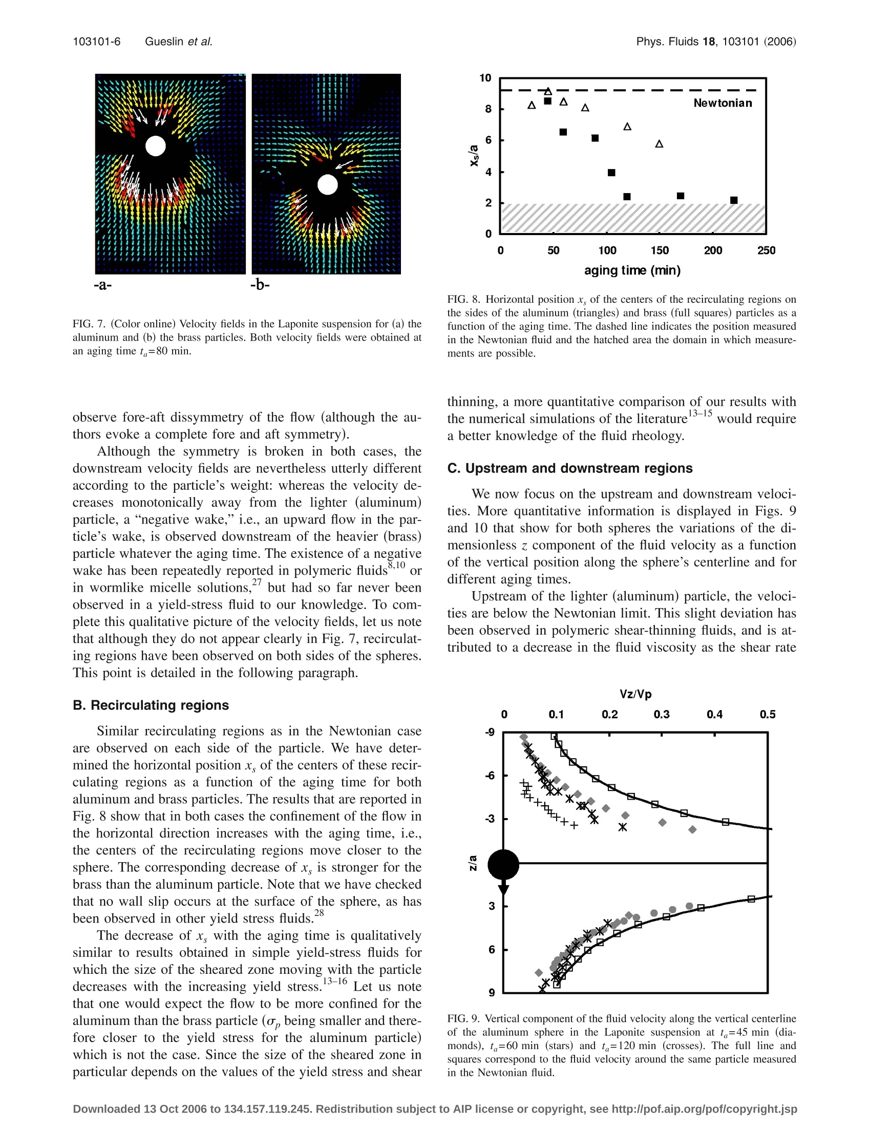
PHYSICS OF FLUIDS 18, 103101 (2006) 103101-2 Gueslin et al.Phys. Fluids 18, 103101 (2006) Flow induced by a sphere settling in an aging yield-stress fluid B. Gueslin Universite Pierre et Marie Curie-Paris 6, CNRS, and Universite Paris-Sud 11, UMR 7608,Orsay F-91405, France and Institut Francais du Petrole, I et 4 avenue de Bois Preau,92852 Rueil Malmaison, France L.Talini Universite Pierre et Marie Curie-Paris 6, CNRS, and Universite Paris-Sud 11, UMR 7608,Orsay F-91405, France B. Herzhaft and Y. Peysson Institut Francais du Petrole, l et 4 avenue de Bois Preau, 92852 Rueil Malmaison,France C. Allain Universite Pierre et Marie Curie-Paris 6, CNRS, and Universite Paris-Sud 11, UMR 7608,Orsay F-91405, France (Received 7 March 2006; accepted 15 August 2006; published online 5 October 2006) I. INTRODUCTION The settling of non-Brownian particles through a non-Newtonian medium is involved in various industrial applica-tions such as drilling of oil and gas wells. During the drillingprocess, a viscous mud is circulated downward through thetubing and upward to the surface. This drilling mud allowsthe removal of rock cuttings from the bottom hole to thesurface, where the solids are separated from the fluid. Mudsalso have to maintain the cuttings in suspension when thefluid circulation is stopped. Drilling fluids exhibit thereforevery complex rheological properties and are commonly de-scribed as thixotropic shear-thinning fluids with a yieldstress. Drilling muds show evidence of strong thixotropy:they develop gel strength when not sheared, and this gelstrength depends on the time of rest. These“aging”proper-ties are usually determined and controlled on site throughnormalized gel measurement, where the stress overshoot be-havior under very low shear is measured as a function of thetime of rest. Usually two measurements are carried out, after10 s (“Gel 0”) and 10 min (“Gel 10”) of rest. Settling of ( “Author to whom correspondence should be a d dressed. Laboratoire FAST, Bat. 502, Campus Universitaire, 91405 Orsay C e dex, France. E l ectronic mail: t alini@fast.u- p sud.fr ) cuttings or of weight material in drilling muds represents animportant issue for the successful completion of a drillingoperation. Transport of cuttings in drilling muds has as wellbeen investigated in order to propose industrial laws for flowrate determination for optimum hole cleaning.Transport ofsolid and settling is also very important in other industrieslike mining where the tailings are transported through a wa-ter and clay mixture. From a fundamental point of view, the settling of a“model"spherical particle through a non-Newtonian mediumhas been the object of numerous studies, either numerical orexperimental, in the past years. Owing to the various rheo-logical properties of non-Newtonian fluids, the resulting fluidflows exhibit a broad range of complex and unexpected fea-tures, some of them remaining poorly understood althoughthe problem of an isolated settling sphere is the simplest thatcan be encountered in sedimentation. In a Newtonian fluid.the creeping flow around a settling sphere presents a fore-aftsymmetry. This symmetry is broken in non-Newtonian fluidsexhibiting various rheological properties even at small Rey-nolds numbers. For instance, a negative wake, i.e., an up-ward motion of the fluid in the particle’s wake, can be ob-served in polymeric fluids that are viscoelastic and shearthinning. .10 Although this effect is well known, its underly- ing physical mechanism is still in debate; some authorshave attributed it to an interplay between shearing stresses inthe particle’s wake that drive a flow away from the sphereand extensional stresses that drive a flow toward the sphere,whereas others invoke a competition between extensionalstress and normal stress differences effects. In the case of yield-stress fluids, numerical results haveshown that during the creeping motion of a sphere in anunbounded Bingham fluid (i.e., a yield-stress fluid with aconstant viscosity and no thixotropy), the flow is confined inthe vicinity of the sphere within an envelope of fluid whosesize depends on the value of the yield stress.3 Outside of thisenvelope the stress is smaller than the yield stress and thefluid is motionless. Similar numerical results have been ob-tained in tubes filled either with Bingham fluids or withHerschel-Bulkley fluids that exhibit both yield stress andshear thinning.The shape of the yielded region indeed de-pends on both the sphere to tube diameter ratio and the varia-tions of the viscosity with the shear rate, but in any case theflow exhibits fore-aft symmetry, and the size of the yieldedregion is a decreasing function of the yield stress. Thesepredictions compare well with measurements performed inpolymeric yield-stress fluids that present both yield stressand shear thinning.16,17 Experimental data on the velocityfield induced by the settling in a yield-stress fluid remainscarce, however, owing in particular to the small number ofyield-stress fluids that are suited for such experimental char-acterizations. Among the existing experimental studies, only a fewdeal with the yield-stress fluids formed by aqueous clay sus-pensions. They yet constitute systems of interest for sedi-mentation studies since, from a fundamental point of view,their structure at the microscopic scale (and thus rheologicalbehavior) utterly differs from the one of the more studiedyield stress polymeric fluids and, from a practical point ofview, they are involved in many industrial processes. Suchfluids have aroused interest in the past years due to theiraging properties. Owing to their microscopic structure,which is still a matter of debate,18-21 the state of these fluidsevolves with time in an irreversible way that depends ontheir mechanical history. In particular, when at rest, theirapparent yield stress increases with time."From a rheologi-cal point of view, they constitute thixotropic fluids that arealso shear thinning above a yield stress. It has been shownthat in such fluids the settling behavior of a spherical particleis more complex than in simple yield-stress fluids. Whereasin the latter fluids one expects the particle velocity to beeither zero or of a constant value according to the relativevalues of the yield stress and the stress exerted by the par-ticle, in Laponite suspensions a settling regime characterizedby a decreasing particle velocity has been observed. Thisbehavior results from the aging of the fluid as the particlesettles. The aim of the present work is to characterize the creep-ing flow induced by a spherical particle settling in a yield-stress fluid that exhibits aging properties, a Laponite suspen-sion. We show in particular that the characteristics of thevelocity field can be strongly modified according to both thestress exerted by the particle on the fluid and the fluid’s age. FIG. 1. Typical image for PIV measurements. The particle (diameter1.5 mm) is moving to the bottom of the picture. The fluid that is seeded withglass microspheres is illuminated from the right of the picture using a lasersheet. The paper is organized as follows: in Sec. II we describe thematerials and experimental procedures, whereas Sec. III isdevoted to the experimental results, and Sec. IV to the mainconclusions. Il.MATERIALS AND PROCEDURES A. Experimental setup The settling cell is made of Plexiglas, is of a rectangularsection (inner dimensions 12 cm×2.4 cm), and of usefulheight 8 cm. Once filled with the fluid, it is sealed with a capthat has been specially designed to release several particlesin the center plane of the cell parallel to its largest walls. Thecap consists of a small tank whose bottom is drilled at regu-lar intervals along the length of the cell; the particles areimmersed in the tank and further released through the holesusing tweezers. This setup enables us to probe the samesample of fluid at different aging times, which is essentialconsidering the poor reproducibility of Laponite suspensions.Only one particle is released through each hole, and we haveverified that the distance between two neighboring holes islarge enough to ensure that the behavior of one particle is notinfluenced by the particles released through other holes. The fluid velocity is measured using the particle imagevelocimetry (PIV) technique. The fluid is therefore seededusing glass hollow microspheres (diameter 10 um) of den-sity close to that of the fluid. The concentration of micro-spheres (0.01% in weight) is small and the fluid rheology isnot modified by their presence within the time scale of theexperiments. The settling plane is illuminated by a lasersheet produced from a He-Ne laser. The width of the sheet is0.5 mm. The motions of the microspheres are imaged using acharge-coupled device (CCD) camera and further digitized.The velocity field is computed using a PIV commercial soft-ware (Davis, LaVision) that cross-correlates two successiveimages separated by a time interval At. A typical image isshown in Fig. 1, where the horizontal and vertical axes aredefined. The optimal range of At has been found to lie be- tween the time needed by the macroscopic particle to moveover its radius and twice that time (the latter correspondingto a displacement of 60 pixels with the chosen magnifica-tion). The horizontal and vertical components (respectively,u, and u) of the fluid velocity in the laboratory frame arethen obtained from the PIV computations. Inherent sourcesof error upon the flow velocity originate from the finite sizeof the microspheres, as well as their “twinkling”in the laserlight. Tests using reference motions have shown that the re-sulting relative error upon the velocity is approximately 5%and that velocities smaller than 0, 1 um/s, cannot be mea-sured properly. Note also that the reflection of the laser lighton the particle and the particle’s shadow (as can be seen inFig. 1) hinder the microspheres’motion, respectively, on theright and left sides of the particle. The velocity along thehorizontal axis of the particle can therefore be determinedonly at sufficiently large distances from the particle Calibrated macroscopic spherical particles of radiusa=0.75 mm and of two different densities have been used:aluminum particles (density 2.7 g/cm’) and brass particles(8.7 g/cm). The velocity V, of the macroscopic particles ismeasured at different aging times using an image processingsoftware (Image Pro+, BFIOptilas) with a precision of 15%.In the case of the PIV measurements, the values of V, usedto normalize the fluid velocity have been measured directlyfrom the PIV images with a precision of 5%. B. Fluid The fluid is an aqueous suspension of Laponite (Rock-wood) that is well known to constitute a transparent thixo-tropic fluid. Since the physicochemical conditions can dra-matically modify the state of the suspensions, special carehas been paid to their preparation: sodium hydroxide isadded to pure water so as to obtain a solution of pH 10; theionic strength is therefore of 10-4 M. Laponite is furtheradded at a concentration of 2.5% w/w under a nitrogen at-mosphere, and the suspension is strongly mixed. Thesamples are then kept under a nitrogen atmosphere for 10days during which they are regularly stirred to ensure a goodhydration of the clay particles. Prior to the settling experi-ments the suspension is stirred at a velocity of 1000 rpm for1 h in order to obtain a reproducible initial state. The fluid isfurther poured in the settling cell and left at rest for a timewe denote as the aging time t . The investigated aging timesrange from 30 to 220 min, during which the fluid evolvesfrom an apparently fluid state to a pasty material. The rheological properties of the Laponite suspensionshave been the object of several studies in the past years. Ithas thus been shown that Laponite suspensions are thixotro-pic yield-stress fluids that present shear-thinning propertiesabove the yield stress.4 The accurate determination of therheological properties of the Laponite suspensions is never-theless not straightforward. In particular, owing to the agingof the fluid, the yield stress is not an intrinsic property butdepends on the mechanical history of the fluid.2 Hencefor-ward, although it is currently stated in the literature that theyield stress of Laponite suspensions increases with age, thenature of this variation has not been systematically docu- FIG. 2. Rheograms obtained with a stress controlled rheometer for differentvalues of the aging time: increasing values of the stress are applied to thefluid and the shear rate is measured for each value of the shear stress. Atlarge shear stresses the shear stress and shear rate are related through thepower-law equation (1) with m=2.0 S.I. and n=0.42 for t =45 min (dia-monds), m=2.5 S.I. and n=0.39 for t=60 min (stars), m=3.0 S.I. andn=0.35 for ta=90 min (dots), m=4.1 S.I. and n=0.30 for ta=120 min(crosses). mented. As far as we know the only attempt to measure thisvariation has been performed with local rheological probes;the authors found that the yield stress increases with the fluida26ging time and may saturate at large aging times. In order to characterize the fluid rheology, we have per-formed stress ramp tests using a controlled stress rheometer.The fluid is first strongly stirred as for a settling experimentand poured in a cylindrical, double-gap Couette flow appa-ratus. At a given aging time the fluid is submitted to a shearstress, increasing at a constant ramp, and the response inshear rate is measured. Although no steady state is reached,these tests provide characterization of the fluid rheology witha weak contribution of the aging since the duration of a mea-surement (10 min) is smaller than the aging times investi-gated. As shown in the stress versus shear rate plots of Fig. 2,the behavior is similar for all aging times: at large shearstresses the fluid is shear thinning and the shear stress andshear rate are related through a power law equation: The parameter m increases for increasing aging timeswhile the index n decreases, indicating that the more the fluidages the more it shear thins. At small shear stresses, thebehavior is still shear thinning but with different parametersm and n, and no yield stress value can be inferred from therheological measurements. These results are not surprisingconsidering the difficulties evoked above in characterizingthe yield stress of Laponite suspensions. In our case, thevalue of the yield stress being small, a more adapted appa-ratus and procedure would be required for an accurate mea-surement. We have not attempted to further characterize thefluid rheology since it is beyond the scope of this paper. C. Dimensional analysis The particle Reynolds number can be estimated as clas-sically in shear-thinning fluids: FIG. 3. Settling velocities of the aluminum (full squares) and brass (tri-angles) particles in the Laponite suspension as a function of its aging time.The experimental data are well described using Eq. (4) (full lines). where pr is the fluid density. The maximal value Reynolds number is of the order of10-2. The effects of inertia are therefore expected to be smallin all the experimental results we present. As shown in the following, the velocity of the particlesstrongly varies according to the fluid’s age. The characteris-tic stress the particles exert on the fluid, o,, can be simplyestimated taking into account the flow induced by the settlingsphere. As classically assumed for spheres settling in non-Newtonian fluids, the characteristic shear rate y, scales asV2a. Further using the relation op=ry, and equating theviscous friction with the gravitational and buoyancy forces,6TnaV,=4Ta'Apg/3 (where Ap is the difference of densi-ties of the fluid and particle and g the acceleration of gravity)finally yields Note that this expression is only expected to provide an orderof magnitude of the stress exerted by the particles of thefluid. The values of o, given by Eq. (3) are, respectively,1.4 Pa for the aluminum particles and 6.3 Pa for brassparticles. D. Particle velocities in the Laponite suspension As shown in Fig. 3, the measurements of the spheresettling velocities reflect the fluid temporal evolution: thevelocities vary by two orders of magnitude within the inves-tigated aging time scale. Note that as previously observed,at small aging times the measured velocity is large such thatits variation along the height of the settling cell remains verysmall, whereas at large aging times the motion is muchslower and the velocity significantly decreases. The variations of the velocity of each particle are welldescribed by FIG. 4. Stress values deduced from the rheological data of Fig. 2 as afunction of the shear ratey,=V,/2a of the aluminum (full squares) andbrass (triangles) particles obtained from the settling data of Fig. 3 fort =45 min, 60 min, 90 min, and 120 min. The data for the aluminum sphereat t =45 min are missing since the corresponding shear rate (3×10⁻³ s-l) isnot within the range investigated in the rheological experiments. The dottedand full lines, respectively, indicate the estimated values of o, for the alu-minum and brass particles using Eq. (3). where Vo is the settling velocity at ta=0 and r is a timeconstant that represents a characteristic aging time. Bothparameters depend on the density of the particle: wehave found Vo=6.0±1.2 mm/s and 7=16.5±1.7 min for thelighter (aluminum)particle, andVo=50±10 mm/sandT=23.5±2.4 min for the heavier (brass) particle. These values are consistent with the simple dimensionalargument previously given to estimate the stress exerted bythe particles on the fluid. Figure 4 shows the stress valuesdeduced from the rheological measurements of Fig. 2 as afunction of the shear ratey=V,/2a obtained from the ve-locity measurements of each sphere at different aging times.Although the stresses are always smaller than the estimatedvalues of r, (indicated by the full and dotted lines), theirvalues remain of the same order of magnitude within theinvestigated range of shear rates that vary by several ordersof magnitude. Information on the yield properties of the fluid is pro-vided by the settling experiments: at large enough agingtimes the particles are observed to stop and remain sus-pended at a given height of the cell for times as long asseveral days. Following Eq.(4), the particle reaches its equi-librium position at infinite aging times. We therefore charac-terized the stoppage of the particles by measuring the verticalposition of the particles that were apparently motionless formore than 10 h. The measurements are in agreement with theequilibrium positions deduced from Eq. (4) within the uncer-tainties of the parameters Vo and r. We can therefore predictthe aging time at which one particle reaches the position5 um above its equilibrium position (5 um being the experi-mental uncertainty upon the position). For aluminum par-ticles (o,=1.4 Pa) we have found ta=230±30 min andta=390±50 min for brass particles (o,=6.3 Pa). The in-crease of the yield stress with the aging time is in agreementwith results obtained in a Laponite suspension of similar FIG. 5. (Color online) Velocity field in the Newtonian fluid. The white circleindicates the average vertical position of the particle. concentration (2.7% in weight).2 The discrepancy in the es-timated values may result from the different geometry andlength scale probed in the given reference, where a dynamicyield stress jis deduced from the rotating motion of amagnetic needle under the effect of an applied magnetictorque. Differences in the preparation of the suspensionsmay also explain this disagreement; in particular, in contrastto the cited work, our fluids are not filtered, which has aprobable consequence on the microscopic structure of thesuspensions. E. Experiments in a Newtonian fluid Preliminary experiments have been conducted in a New-tonian fluid (pure glycerol) in order to calibrate the PIV mea-surements. Aluminum particles were used and the Reynoldsnumber was Re=2×10⁻³. Figure 5 shows the correspondingvelocity field around the settling sphere. It exhibits a fore-aftsymmetry as expected at small Re. Note that this symmetryis not obvious in Fig. 5 owing to the representation of thePIV vectors: each vector corresponds to the velocity of thepoint lying at its origin. The indicated position of the spherecorresponds to its average position between times t andt+At. The recirculating regions on both sides of the sphere areconsequences of the finite size of the cell. The centers ofthese regions are located at (9.3±0.2) radii from the sphere’scenter which roughly corresponds to the mid-distance fromthe cell sidewall and the sphere’s center. This result is inagreement with experimental data obtained in a cylindricalcell." To our knowledge no data on the settling in a rectan-gular cell are available in the literature. Nevertheless, withinthe distances we probe, the lack of axisymmetry of the celldoes not significantly modify the velocity field from the onein a cylindrical cell. Figure 6 shows the variations of the dimensionless zcomponent of the fluid velocity as a function of the verticalposition along the sphere’s centerline. The experimental dataare compared with the Stokes’calculations for the velocity inan unbounded fluid. Away from the sphere the velocity de-creases to zero faster than in an unbounded fluid and signifi-cant differences are observed for z/a≥5. The downstream 0.2 1 FIG. 6. Vertical component of the fluid velocity along the vertical centerlineof the aluminum sphere in the Newtonian fluid. The full line represents theStokes’solution. and upstream velocity disturbances nevertheless extend far-ther than the visualization window. Note that in a cylindricalcell they are expected to be confined within a distance closeto the width of the cell.° Close to the sphere’s surface (z/a≤2) large discrepan-cies from Stokes’calculations are observed (experimentaldata not shown) owing to the principle of PIV computations:thevectors obtained by PIV do not correspond to the instan-taneous velocities of fluid particles, but to their displace-ments over a time spacing At during which the sphere itselfmoves (z=0 corresponds to its average vertical position be-tween times t and t+At). The correction resulting from thistemporal averaging can be computed by integrating theexpression for the fluid velocity over At, and we have foundit to be in agreement with the experimental data; no othersource of error is therefore involved in the observed discrep-ancy. The correction is close to 20% for z/a=1.5, whereasit becomes smaller than the experimental uncertainty forz/a=2.5. In conclusion, despite their unreliability in the vicinity ofthe sphere’s surface (within 1 radius), the PIV measurementsshow a good agreement with the velocity field expected in aNewtonian fluid. III. VELOCITY FIELDS IN THE LAPONITE SUSPENSION A. Qualitative description Figure 7 shows the velocity fields around the aluminumand brass particles at the same aging time. Note that thevectors scales are different in both figures since the particlevelocities differ by two orders of magnitude. The fore-aftsymmetry observed in a Newtonian fluid is broken for bothparticles in the Laponite suspension. In both cases the flowtherefore qualitatively differs from the one predicted and ob-served in non-thixotropic yield-stress fluids. 3-16 Note that,in the cited experimental study,the sphere being moved ata constant speed for the flow visualization, a rod is attachedat its rear stagnation point, which may make it difficult to -a- -b- FIG. 7. (Color online) Velocity fields in the Laponite suspension for (a) thealuminum and (b) the brass particles. Both velocity fields were obtained atan aging time ta=80 min. observe fore-aft dissymmetry of the flow (although the au-thors evoke a complete fore and aft symmetry). Although the symmetry is broken in both cases, thedownstream velocity fields are nevertheless utterly differentaccording to the particle’s weight: whereas the velocity de-creases monotonically away from the lighter (aluminum)particle, a“negative wake,”i.e., an upward flow in the par-ticle’s wake, is observed downstream of the heavier (brass)particle whatever the aging time. The existence of a negativewake has been repeatedly reported in polymeric fluids,'oOrin wormlike micelle solutions.but had so far never beenobserved in a yield-stress fluid to our knowledge. To com-plete this qualitative picture of the velocity fields, let us notethat although they do not appear clearly in Fig. 7, recirculat-ing regions have been observed on both sides of the spheres.This point is detailed in the following paragraph. B. Recirculating regions Similar recirculating regions as in the Newtonian caseare observed on each side of the particle. We have deter-mined the horizontal position x, of the centers of these recir-culating regions as a function of the aging time for bothaluminum and brass particles. The results that are reported inFig. 8 show that in both cases the confinement of the flow inthe horizontal direction increases with the aging time, i.e.,the centers of the recirculating regions move closer to thesphere. The corresponding decrease of x, is stronger for thebrass than the aluminum particle. Note that we have checkedthat no wall slip occurs at the surface of the sphere, as hasbeen observed in other yield stress fluids.28 The decrease of x, with the aging time is qualitativelysimilar to results obtained in simple yield-stress fluids forwhich the size of the sheared zone moving with the particledecreases with the increasing yield stress.13-16 Let us notethat one would expect the flow to be more confined for thealuminum than the brass particle (o, being smaller and there-fore closer to the yield stress for the aluminum particle)which is not the case. Since the size of the sheared zone inparticular depends on the values of the yield stress and shear FIG. 8. Horizontal position x, of the centers of the recirculating regions onthe sides of the aluminum (triangles) and brass (full squares) particles as afunction of the aging time. The dashed line indicates the position measuredin the Newtonian fluid and the hatched area the domain in which measure-ments are possible. thinning, a more quantitative comparison of our results withthe numerical simulations of the literature13-15would requirea better knowledge of the fluid rheology. C. Upstream and downstream regions We now focus on the upstream and downstream veloci-ties. More quantitative information is displayed in Figs. 9and 10 that show for both spheres the variations of the di-mensionless z component of the fluid velocity as a functionof the vertical position along the sphere’s centerline and fordifferent aging times. Upstream of the lighter (aluminum) particle, the veloci-ties are below the Newtonian limit. This slight deviation hasbeen observed in polymeric shear-thinning fluids, and is at-tributed to a decrease in the fluid viscosity as the shear rate Vz/Vp FIG. 9. Vertical component of the fluid velocity along the vertical centerlineof the aluminum sphere in the Laponite suspension at ta=45 min (dia-monds), t=60 min (stars) and t =120 min (crosses). The full line andsquares correspond to the fluid velocity around the same particle measuredin the Newtonian fluid. FIG. 10. Vertical component of the fluid velocity along the vertical center-line of the brass sphere in the Laponite suspension at t =45 min (diamonds),ta=60 min (stars) and t =105 min (full circles), ta=120 min (crosses) andt =170 min (full triangles). increases closer to the sphere. As shown in Fig. 7, no sig-nificant influence of the aging time on this deviation is ob-served. This is not the case downstream of the particle,where the velocity is much smaller than in a Newtonian fluidand decreases faster away from the particle as the aging timeincreases. As mentioned earlier, the shear-thinning propertiesof the Laponite suspension increase with the aging time,which is consistent with the increasing confinement of thedownstream flow. In the case of the heavier (brass) particle, the upstreamflow is even more confined and, as observed in the horizontaldirection (results not shown), its confinement increases withthe aging time, which is once more consistent with the exis-tence of yielded and unyielded zones. The presence of anegative wake, however, prevents further comparison be-tween this flow and the one in a simple yield-stress fluid. The features of the negative wakes shown in Fig. 10 arefurthermore quantitatively different from the ones observedin shear-thinning polymeric fluids. In particular, the stagna-tion point in the particle’s wake moves closer to the particleas the aging time increases. In polymeric shear-thinning flu-ids, the position of the stagnation point has been found to beindependent of the Deborah number, i.e., the ratio of thecharacteristic fluid relaxation time with the flow characteris-tic time, the latter scaling as a/V. In micelle solutions,however, the stagnation point moves away from the sphereas De increases.In a Laponite suspension, the viscoelasticrelaxation time varies with the aging time.24,26 It has further-more been shown that at large enough aging times and lengthscales, 29.the relaxation time is proportional to t Taking intoaccount the variations of the velocity with the aging time asdescribed in Eq. (4), the Deborah number is thus expected to vary as taVo/2ae-dr. Since the experiments are performedwithin ta>r for both particles, one expects the Deborahnumber to decrease with increasing aging times. Our resultsare therefore in qualitative agreement with the ones obtainedin micelle solutions. IV.CONCLUSIONS We have shown that the features of the flow induced bya particle settling in an aging yield-stress fluid strongly de-pend on the characteristic stress exerted by the particle. De-spite the stresses exerted by the two chosen particles being ofthe same order of magnitude, the flow confinement as well asthe velocity in the particle’s wake strongly differs from oneanother. We have also shown that no symmetric sheared zonearound the particle is observed as has been predicted andobserved in non-thixotropic, yield-stress fluids. Thixotropytherefore not only induces time-dependent rheological prop-erties, but also results in a breaking of the fore-aft symmetry.Whereas the existence of a yield stress can be inferred fromthe settling behavior, its influence on the velocity fieldaround the particles is not obvious. Although the exact criterion for the presence of a nega-tive wake is still in debate, the fluid extensional propertiesdoubtlessly play a crucial role in the apparition of a negativewake. A better knowledge of the extensional rheology of theLaponite suspensions is therefore needed to understand thepresent results. Such measurements have never been per-formed as far as we know. Laponite suspensions being con-stituted of colloidal disks whose interactions remain weak.their extensional viscosity is expected to be small comparedto the one ofpolymeric fluids; accurate measurements of theextensional viscosity of Laponite suspensions should there-fore constitute a difficult task. Finally let us note that although the flows around the twodifferent particles are qualitatively different, the settling be-haviors remain similar. The correlation between the velocityfield and the drag factor is therefore not obvious in the caseof the Laponite suspensions. ACKNOWLEDGMENTS We thank F. Moisy for his help in the PIV experimentsand R. J. Phillips for critical reading of the manuscript. Thethesis of B.G. is partially funded by ANRT. ( A. Saasen,“ S ag of weight materials in oil based drilling fluids,”Society of Petroleum Engineer Paper No. IADC/SPE 77190 ( 2 002). ) ( Y. Luo, P . A. Bern, B . D. C h ambers, an d D. S. Kellingray,“Simple charts to determine h ole c leaning r equirements i n deviated wells,”Society ofPetroleum E ngineer Paper No. IADC/SPE 77190 (2002). ) ( R . K. Clark and K. L. B ickham,“A me c hanistic mo d el for cu t tings t r ans-port , ” Society of Petroleum Engineer P aper N o. 28306 ( 1 994). ) ( “ C. A . S hook and M . C. Roco, Sl u rry Flow—Principle s and Practice, Se- ries in Chemical E ngineering ( Butterworth-Heinemann, Stoneham, MA , 1991). ) R. P. Chhabra, Bubbles, Drops and Particules in Non-Newtonian Fluids(CRC Press, Boca Raton, FL, 1993). ( G. H . McKinley,“St e ady and t ransient moti o n of spherical part i cles in ) ( viscoelastic fluids , ” in Transpor t Processe s i n Bubbles , Drops and P ar- ticles , edited b y R . P. Chhabr a an d D. D. Kee (Taylor & Francis, New Y ork, 2001 ) . ) ( 'M. T. Arigo, D. Rajagopalan , N . Shapley, and G. H . McKinley,“The s edimentation of a sphere through an elastic fluid, Part 1: S teady motion,"J. Non-Newtonian Fluid M ech. 60, 2 25(1995). ) ( M.T. Arigo and G. H. McKinley,“An e xpe r imental inve s tigation of n ega-tive wakes behind spheres settling in a sh e ar-thinning visc o elastic fl u id," R heol. A cta 3 7, 3 07 (1998). ) ( D. Fabris, S. J . Muller, and D. Liepmann,“Wake measurements for a flow a round a s p here i n a viscoelastic f luid," Phys. Fluids 1 1, 3559 ( 1999). ) ( 0. H a ssager,“ N egative wake behind bubbles i n non-Newtonian liquids," Nature 279,402(1979). ) ( O. G. Harlen, “ The n e gative wake behind a sphere s e dimenting through aviscoelastic fluid, ” J. Non-Newtonian F l uid Mech. 10 8 , 41 1 ( 2 0 02). ) ( M. B. Bush,“O n the stagnation flow behind a sphere in a shear-thinning v iscoelastic fluid,”J. Non-Newtonian F l uid M e ch. 55 , 22 9 (199 4 ). ) A. N. Beris, J. A. Tsamopoulos, R. C. Armstrong, and R. A. Brown,“Creeping motion of a sphere through a Bingham plastic,”J. Fluid Mech.158,219 (1985). ( "J. Blackery and E. Mitsoulis, “Creeping motion of a sphere in t u bes fill e dwith a Bingham p lastic material , ”J.Non-Newtonian Fluid Mech. 7 0, 59 (1997). ) M. Beaulne and E.Mitsoulis, “Creeping motion of a sphere in tubes filledwith Herschel-Buckley fluids,”J. Non-Newtonian Fluid Mech. 72, 55(1997). D. D. Attapatu, R. P. Chhabra, and P. H. T. Uhlherr, “Creeping spheremotion in Herschel-Buckley fluids: flow field and drag," J. Non-NNeewtWonian Fluid Mech. 59, 245 (1995). ( O.Me r kak,L. J o s sic, a n d A . Magnin,“Spheres and interactions betweenspheres m oving at very lo w vel o cities in a yie l d stress fluid,”J. N o n - Newtonian F luid Mech. 1 33,9 9 (2006). ) F. Pignon,J. M. Piau, and A. Magnin,“Structure and pertinent length scaleofa discotic clay gel," Phys. Rev. Lett. 76,4857 (1996). D. Bonn, H. Kellay, H. Tanaka, G. Wegdam, and J. Meunier,“Laponite:what is the difference between a gel and a glass ?"Langmuir 15, 7534(1999). 2P. Levitz, E. Lecolier, A. Mourchid, A. Delville, and S. Lyonnard,“Liquid-solid transition of Laponite suspensions at very low ionicstrength: Long-range electrostatic stabilisation of anisotropic colloids,"Europhys. Lett. 49, 672 (2000). P. Mongondry, “Structure et comportement rheolgique des suspensionsaqueuses de Laponite en presence de plusieurs additifs," Ph. D. thesis,University of Maine-Le Mans, 2003. "N. P. Chafe and J. R. de Bruyn, "Drag and relaxation in a bentonite claysuspension,”J. Non-Newtonian Fluid Mech. 131,44 (2005). 2T. Ferroir, H. T. Huynh, X. Chateau, and P. Coussot, “Motion of a solidobject through a pasty (thixotropic) fluid," Phys. Fluids 16, 594 (2004). “D. Bonn, S. Tanase, B. Abou, H. Tanaka, and J. Meunier, “Laponite: agingand shear rejuvenation of a colloidal glass,” Phys. Rev. Lett. 89, 015701(2002). P. Coussot, Q. D. Nguyen, H. Y. Huynh, and D. Bonn, “Avalanche behav-ior in yield stress fluids, Phys. Rev. Lett. 88, 175501 (2002). C. Wilhelm, F. Elias, J. Browaeys, A. Ponton, and J. C. Bacri,“Localrheological probes for complex fluids: Application to Laponite suspen-sions," Phys. Rev. E 66,021502(2002). S. Chen and J. P. Rothstein,“Flow of a wormlike micelle solution past afalling sphere,”J. Non-Newtonian Fluid Mech. 116, 205 (2004). 2L. Jossic and A. Magnin, “Drag and stability of objects in a yield stressfluid,” AIChE J. 47, 2666 (2001). "M. Bellour, A. Knaebel, J. L. Harden, F. Lequeux, and J.-P. Munch,“Ag-ing processes and scale dependence in soft glassy colloidal suspensions,"Phys. Rev. E 67,031405(2003). /$ American Institute of PhysicsDownloaded Oct to Redistribution subject to AIP license or copyright, see http://pof.aip.org/pof/copyright.jsp Downloaded Oct to Redistribution subject to AIP license or copyright, see http://pof.aip.org/pof/copyright.jsp
确定


还剩6页未读,是否继续阅读?

产品配置单

北京欧兰科技发展有限公司为您提供《老化,屈服应力,流体,球形沉降物中速度场,速度矢量场检测方案(粒子图像测速)》,该方案主要用于其他中速度场,速度矢量场检测,参考标准--,《老化,屈服应力,流体,球形沉降物中速度场,速度矢量场检测方案(粒子图像测速)》用到的仪器有德国LaVision PIV/PLIF粒子成像测速场仪
推荐专场


相关方案
更多
该厂商其他方案
更多