


方案详情
文
This paper presents flow field measurements of hydrogen/methane mixtures under near blowout
conditions. Previous high speed visualizations by our group of these flames shows that the blow off
phenomenology varies with percentage of hydrogen [1]. This paper further characterizes the flow field of these
flames using particle image velocimetry (PIV). A variety of highly dynamic flame and flow features are observed,
which vary substantially with the H2 levels in the fuel. This variation is apparently due to the enhanced strain
resistance of hydrogen augmented flames and flow dilatation ratio effects upon flow dynamics, particularly vortex
breakdown.
方案详情

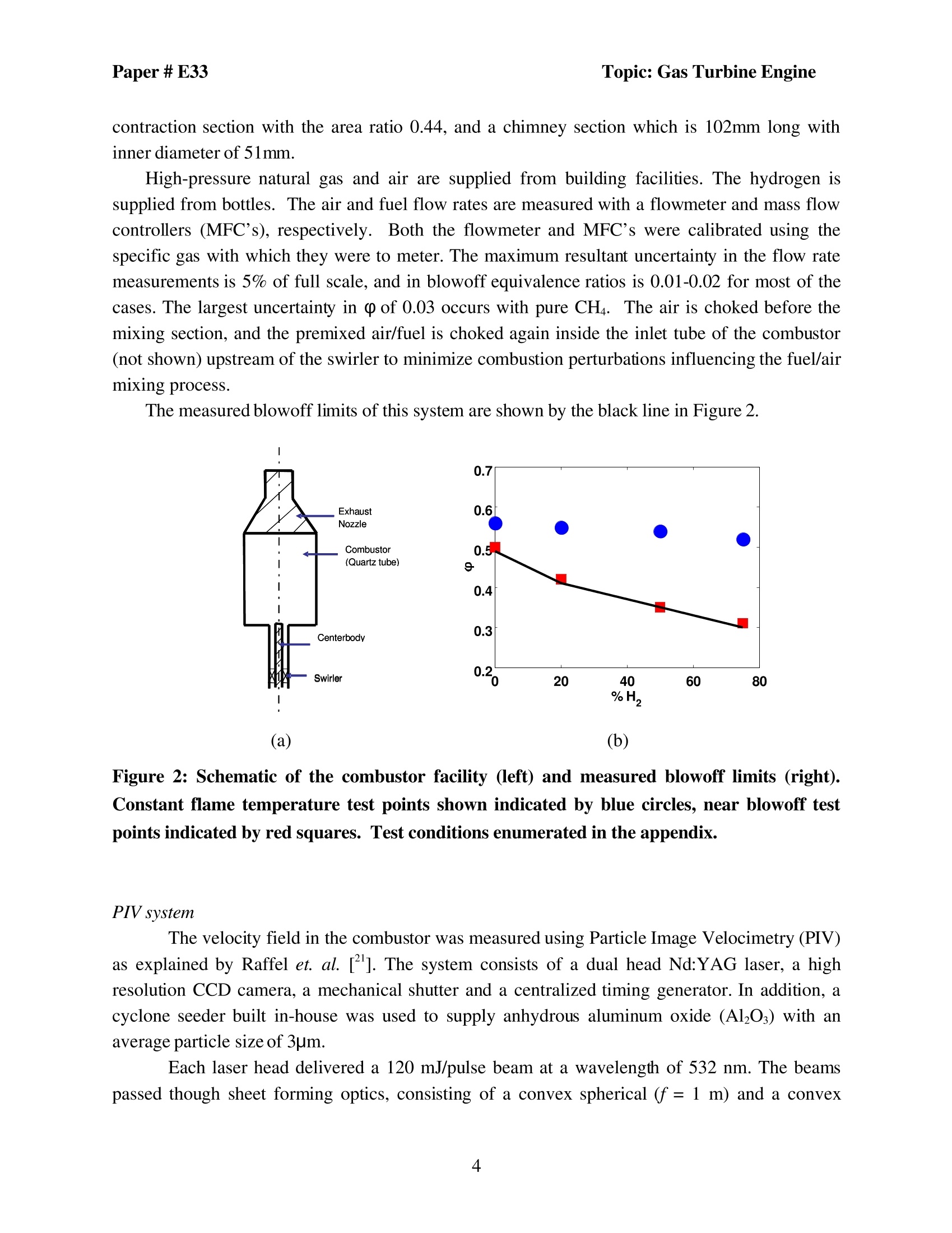
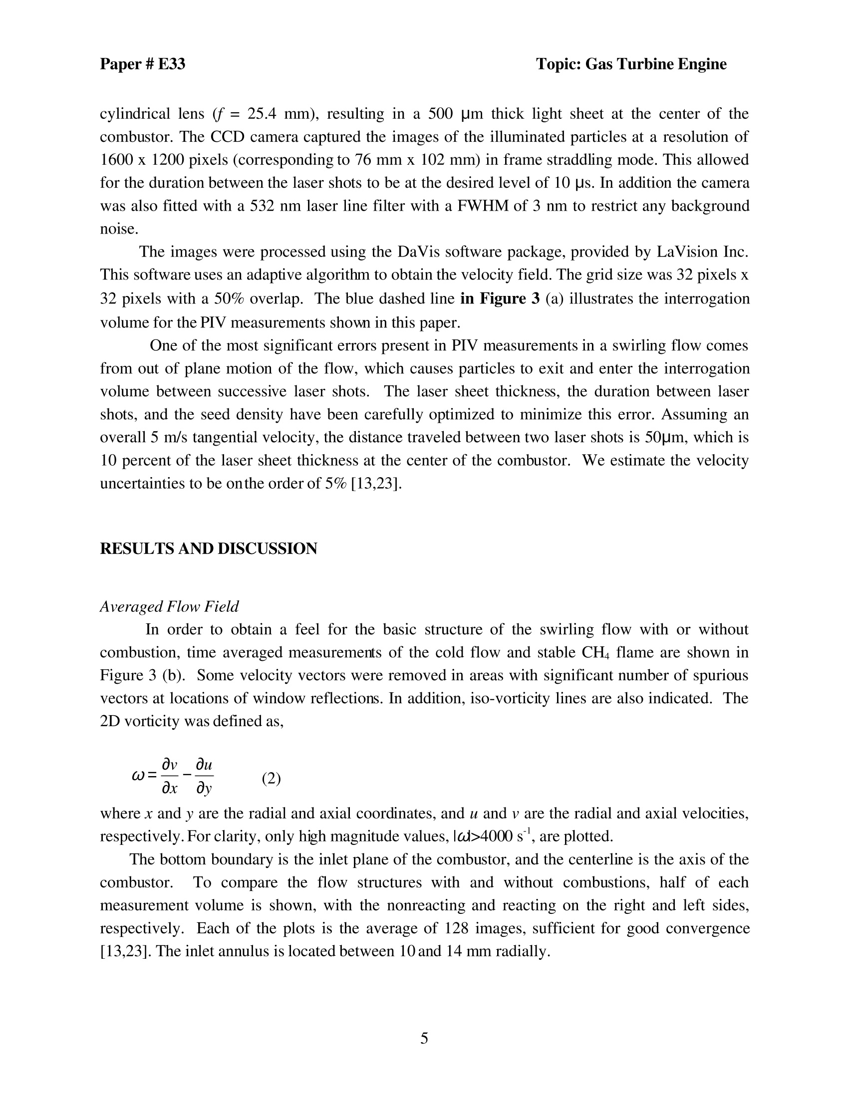
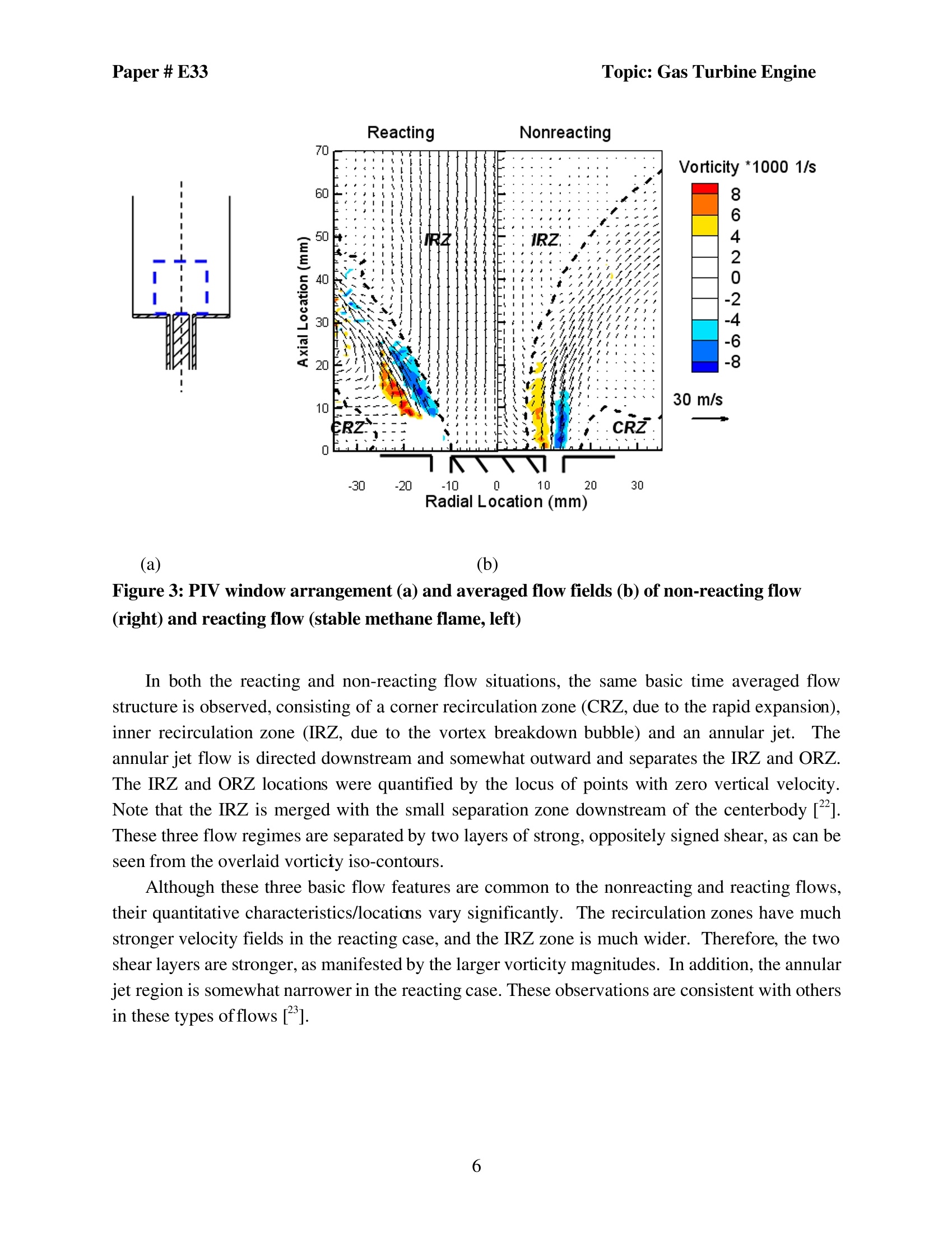
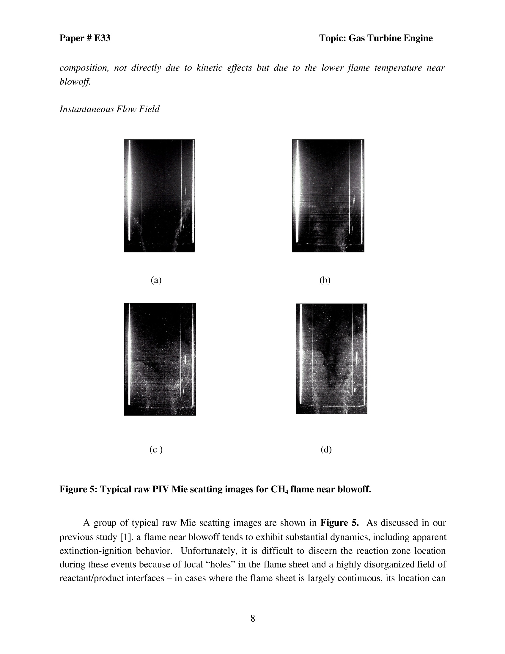
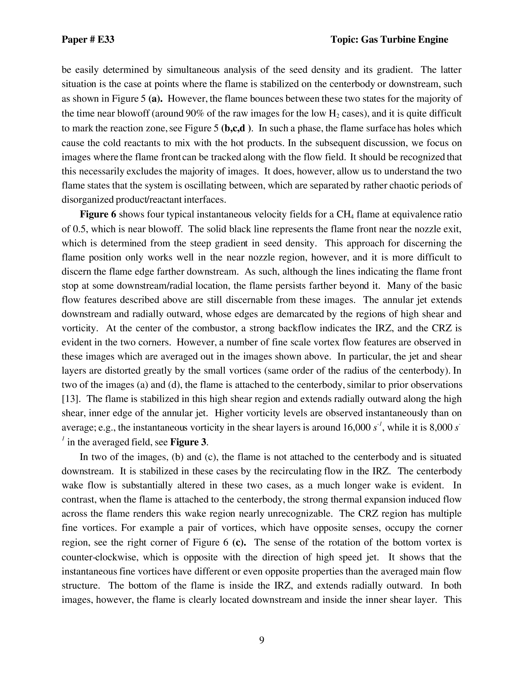
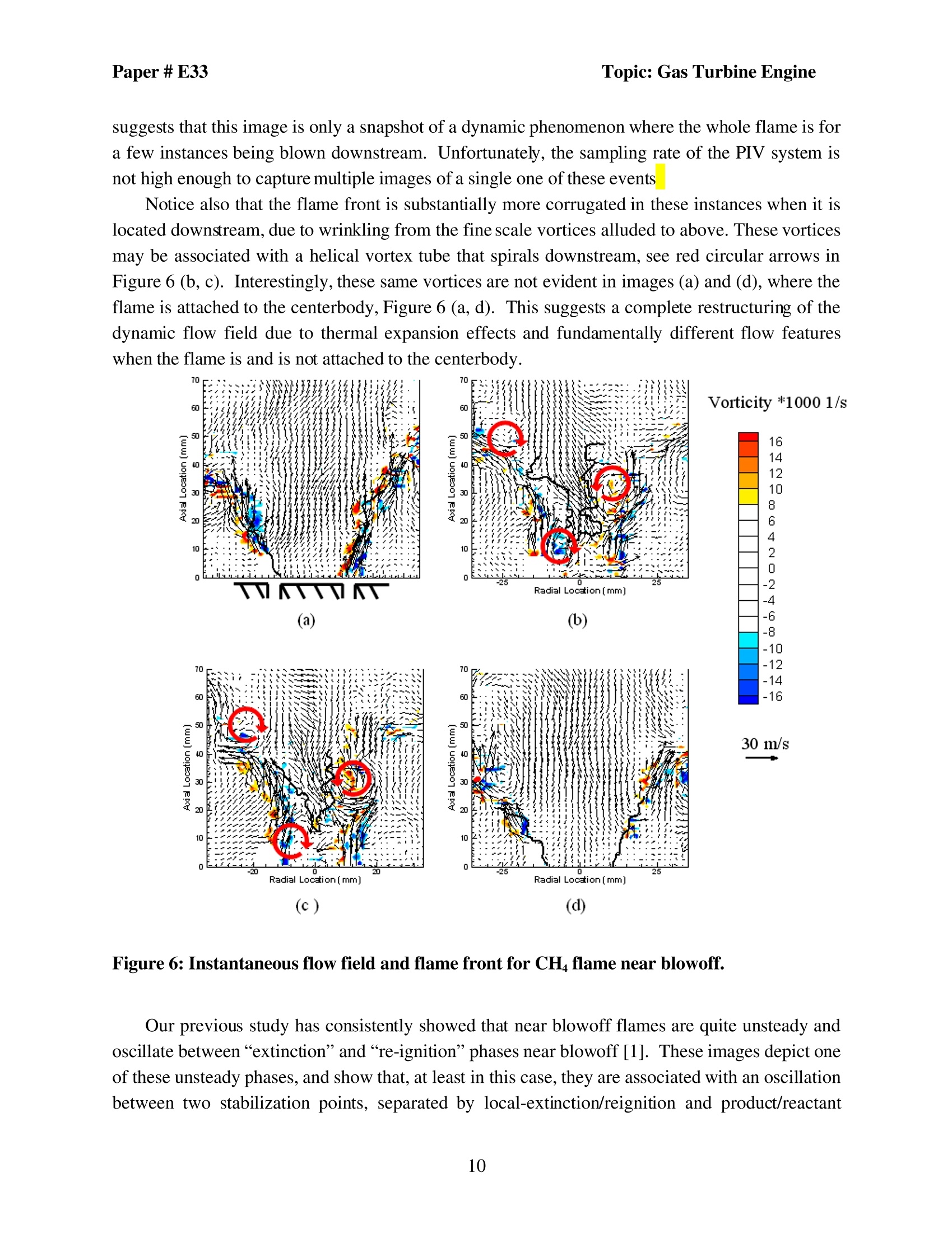
Topic: Gas Turbine EnginePaper# E33 Topic: Gas Turbine EnginePaper#E33 5th US Combustion MeetingOrganized by the Western States Section of the Combustion Instituteand Hosted by the University of California at San DiegoMarch 25-28.2007 PIV Measurements in H/CH4 Swirling Flames under nearBlowoff Conditions Qingguo Zhang, David R. Noble, Santosh J. Shanbhogue and Tim Lieuwen School ofAerospace EngineeringGeorgia Institute ofTechnologyAtlanta, GA 30332-0150 ABSTRACT This paper presents flow field measurements of hydrogen/methane mixtures under near blowoutconditions. Previous high speed visualizations by our group of these flames shows that the blow offphenomenology varies with percentage of hydrogen []. This paper further characterizes the flow field of theseflames using particle image velocimetry (PIV). A variety of highly dynamic flame and flow features are observed,which vary substantially with the H levels in the fuel. This variation is apparently due to the enhanced strainresistance of hydrogen augmented flames and flow dilatation ratio effects upon flow dynamics, particularly vortexbreakdown. Keyword: hydrogen, lean blowout,swirling INTRODUCTION This paper presents flow field measurements of hydrogen/methane mixtures under nearblowout conditions. This work is motivated by interest in developing combustors capable of highH operation, while producing minimal air pollutants.Prior experience with low emissionscombustion systems [] has indicated that several operational and performance issues are ofconcern, including blowout, flashback, combustion instabilities, and emissions []. The issue oflean blowout is the focus of this study, a concern due to the requirement to operate low NOxsystems under very fuel lean conditions and, therefore, close to their blowofflimits. A large literature on predicting, measuring, and correlating blowoff limits already exists [,,,,]. One of the key attractive qualities of hydrogen enriched fuels is their enhanced resistance to blowoff relative to natural gas. As such, a H2 doped mixture can potentially be operated stablyat a lower flame temperature, and therefore with lower NOx emissions []. Several recent studieshave focused on H/CH4 flames [10,11,1213] and shown that small additions of H substantiallyenhances the mixture's resistance to extinction or blowoff. The acceleration of the CH4 reactionrate by the radical pool created by the early breakdown of H has been suggested as a keymechanism for this behavior.For example, fundamental studies in opposed flow burnergeometries show that the extinction strain rate of methane flames is doubled with the addition of10% H [4,1s]. Similarly, extension of blowout limits in combustors operating with H enrichedfuels has been reported in a number of publications [10-13,6,17]. For example, our group hasobtained measurements of the blowout conditions of CH/CO/H2 mixtures over a range ofpressures and inlet temperatures. These results indicate that there is a monotonic reduction inequivalence ratio (left) and adiabatic flame temperature (right) at blowout with increases in H2levels in the fuel [], see Figure 1. Figure 1: Dependence of equivalence ratio (Left) and adiabatic flame temperature (Right) atLBO upon percentage of H at premixer velocity of 59 m/s, inlet temperature of 458 K and4.4 atmospheres However, in this same study, it was noted that the phenomenology of blowoff changedmarkedly with H levels in the fuel. For lower H2 mixtures (~<50%H by volume), the blowoffevent occurred abruptly and was precipitated by a small reduction in fuel/air ratio (althoughsometimes preceded by slight liftoff of the flame from the burner). However, for high H2mixtures, the flame liftoff and blowoff events were quite distinct. Furthermore, as the mixtureapproached blowoff, the flame became visibly weaker, lifted off from the holder and movedprogressively downstream. Finally, it was noted that the definition of blowoff at these very highH levels was somewhat arbitrary and very much a function of the definition of “blowoff". In a subsequent high speed imaging study of our group, we studied the dynamic blowoffprocess of different H/CH mixtures [1]. It reported that, near blowoff, a variety of highly dynamic flame features are observed, which vary substantially with the H levels in the fuel.These features involve complex interactions between the inner recirculation zone (vortexbreakdownbubble), outer recirculation zone oftherrapidexpansion,andflameextinction/reignition phenomenon. In addition, a columnar flame shape was observed for highhydrogen flame. However, the relative role of fluid mechanics and kinetics in these dynamicfeatures was unclear. The objective of this paper is to follow up on these observations and to further characterizethe flow field of these flames using particle image velocimetry (PIV). It should be emphasized thatthis blowoff phenomenology is geometry dependent and is a function of, for example, the degreeof constriction of the exhaust nozzle. As such, we took special effort to perform this study on awell characterized burner that is identical to studies performed at Sandia National Laboratory. INSTRUMENTATION AND FACILITY Combustor and flow control system Measurements were obtained in a lean, premixed swirl, combustor which is duplicated froman experimental rig developed at Sandia National Laboratories by Dr. Bob Schefer and Dr. JoeOefelein []. This was done in order to have the same test facility to facilitate comparisons of dataand simulations with the Sandia group. The combustor is shown in (a). The facility consists of aswirler/nozzle,combustor, and exhaust sections. Premixed gas, consisting of H/CH4 mixtures andair flows through a swirler housed swirler/nozzle section. The nozzle is an annular tube with innerdiameter of 28mm. The center body has an outer diameter of 20 mm. The overall flow arearemains constant at 3.0 cm inside the nozzle. Tests were performed with a six-vane, 45°swirler,which is located in the annulus between the centerbody and nozzle wall. TThe theoretical swirlnumber,which is 0.86, is calculated by ["], where dnand d are the diameters of centerbody and swirler, respectively, and 0 is the swirler vaneangle. The fuel is injected 150 cm upstream of the combustor to achieve a premixed condition.The combustor consists of a 305 mm (12 inches) long quartz tube, which permits the detection ofultraviolet (UV) radiation and imaging. The quartz tube has an inner diameter of 115 mm and restsin a circular groove in a base plate. An adapter slides in four standing bars, sitting on the top of thequartz tube, and the exhaust nozzle is connected to the adapter. The exhaust nozzle has a 127mm contraction section with the area ratio 0.44, and a chimney section which is 102mm long withinner diameter of 51mm. High-pressure natural gas and air are supplied from building facilities. The hydrogen issupplied from bottles. The air and fuel flow rates are measured with a flowmeter and mass flowcontrollers (MFC’s), respectively. lBoth the flowmeter and MFC’s were calibrated using thespecific gas with which they were to meter. The maximum resultant uncertainty in the flow ratemeasurements is 5% of full scale, and in blowoff equivalence ratios is 0.01-0.02 for most of thecases. The largest uncertainty in 中 of 0.03 occurs with pure CH4. The air is choked before themixing section, and the premixed air/fuel is choked again inside the inlet tube of the combustor(not shown) upstream of the swirler to minimize combustion perturbations influencing the fuel/airmixing process. The measured blowoff limits of this system are shown by the black line in Figure 2. 80 (a) (b) Figure 2: Schematic of the combustor facility (left) and measured blowoff limits (right).Constant flame temperature test points shown indicated by blue circles, near blowoff testpoints indicated by red squares. Test conditions enumerated in the appendix. PIV system The velocity field in the combustor was measured using Particle Image Velocimetry (PIV)as explained by Raffel et. al. ["]. The system consists of a dual head Nd:YAG laser, a highresolution CCD camera, a mechanical shutter and a centralized timing generator. In addition, acyclone seeder built in-house was used to supply anhydrous aluminum oxide (Al2O3) with anaverage particle size of 3um. Each laser head delivered a 120 mJ/pulse beam at a wavelength of 532 nm. The beamspassed though sheet forming optics, consisting of a convex spherical (f=1 m) and a convex cylindrical lens (f= 25.4 mm), resulting in a 500 um thick light sheet at the center of thecombustor. The CCD camera captured the images of the illuminated particles at a resolution of1600 x 1200 pixels (corresponding to 76 mm x 102 mm) in frame straddling mode. This allowedfor the duration between the laser shots to be at the desired level of 10 us. In addition the camerawas also fitted with a 532 nm laser line filter with a FWHM of 3 nm to restrict any backgroundnoise. The images were processed using the DaVis software package, provided by LaVision Inc.This software uses an adaptive algorithm to obtain the velocity field. The grid size was 32 pixels x32 pixels with a 50% overlap. The blue dashed line in Figure 3 (a) illustrates the interrogationvolume for the PIV measurements shown in this paper. One of the most significant errors present in PIV measurements in a swirling flow comesfrom out of plane motion of the flow, which causes particles to exit and enter the interrogationvolume between successive laser shots.The laser sheet thickness, the duration between lasershots, and the seed density have been carefully optimized to minimize this error. Assuming anoverall 5 m/s tangential velocity, the distance traveled between two laser shots is 50um, which is10 percent of the laser sheet thickness at the center of the combustor. We estimate the velocityuncertainties to be onthe order of 5%[13,23]. RESULTS AND DISCUSSION Averaged Flow Field In order to obtain a feel for the basic structure of the swirling flow with or withoutcombustion, time averaged measurements of the cold flow and stable CH flame are shown inFigure 3 (b). Some velocity vectors were removed in areas with significant number of spuriousvectors at locations of window reflections. In addition, iso-vorticity lines are also indicated. The2D vorticity was defined as, where x and y are the radial and axial coordinates, and u and v are the radial and axial velocities,respectively. For clarity, only high magnitude values, lwl>4000 s, are plotted. The bottom boundary is the inlet plane of the combustor, and the centerline is the axis of thecombustor. To compare the flow structures with and without combustions, half of eachmeasurement volume is shown, with the nonreacting and reacting on the right and left sides,respectively. Each of the plots is the average of 128 images, sufficient for good convergence[13,23]. The inlet annulus is located between 10 and 14 mm radially. (a) (b) Figure 3: PIV window arrangement (a) and averaged flow fields (b) of non-reacting flow(right) and reacting flow (stable methane flame, left) In both the reacting and non-reacting flow situations, the same basic time averaged flowstructure is observed, consisting of a corner recirculation zone (CRZ, due to the rapid expansion),inner recirculation zone (IRZ, due to the vortex breakdown bubble) and an annular jet.Theannular jet flow is directed downstream and somewhat outward and separates the IRZ and ORZ.The IRZ and ORZ locations were quantified by the locus of points with zero vertical velocity.Note that the IRZ is merged with the small separation zone downstream of the centerbody ["].These three flow regimes are separated by two layers of strong, oppositely signed shear, as can beseen from the overlaid vorticty iso-contours. Although these three basic flow features are common to the nonreacting and reacting flows,their quantitative characteristics/locations vary significantly. The recirculation zones have muchstronger velocity fields in the reacting case, and the IRZ zone is much wider. Therefore, the twoshear layers are stronger, as manifested by the larger vorticity magnitudes. In addition, the annularjet region is somewhat narrower in the reacting case. These observations are consistent with othersin these types offlows ["]. 8eldFlow 20% H, 50% H, 75%HH, Radiall aratian(mm) Figure 4: Contour lines of zero mean axial velocity for flames at the same adiabatic flametemperature (Left half) and near blowoff (Right half). In order to better understand the relative role of chemical kinetics and fluid mechanics in thissystem, a set of data were obtained where the relative H/CH mole fractions were varied, but byadjusting the overall mixture stoichiometry such that the gas expansion ratio across the flame andadiabatic flame temperature (calculated) remained nearly constant at 1590K. These test points areshown in Figure 2. Details of the stoichiometries and test conditions are shown in the appendix.Results illustrating the time averaged location ofthe IRZ and CRZ boundaries areshown in the lefthalf of Figure 4. These results show that all four reacting cases have essentially identical IRZboundaries, regardless of the fuel H/CH4 ratio. This result suggests that kinetic effects do notimpact the average flow field structure of constant temperature flames- rather, that it is controlledby the thermal expansion ratio acrossthe flame. Because the flames with higher hydrogen levels blow out at lower fuel/air ratio’s and flametemperatures, the thermal expansion ratio across the flame is different for the near blowoff flameswe consider in this paper; these test points are illustrated in Figure 2 (b). Although the flameshows a strongly dynamic behavior when blowoff is approached,for completeness we plot thecorresponding flow boundaries for the near blowoff cases in the right half of Figure 4. This figureshows that the size of the IRZ reduces as the percentage of H increases, apparently correspondingto the decrease in expansion ratio across the flame. As such, the fluid mechanic structure of theflow for the near blowoff flames considered in more detail below certainly varies with the fuel Topic: Gas Turbine Engine composition, not directly due to kinetic effects but due to the lower flame temperature nearblowoff Instantaneous Flow Field (a) (b) (c) (d) Figure 5: Typical raw PIV Mie scatting images for CH flame near blowoff. A group of typical raw Mie scatting images are shown in Figure 5. As discussed in ourprevious study [1], a flame near blowoff tends to exhibit substantial dynamics, including apparentextinction-ignition behavior.. Unfortunately, it is difficult to discern the reaction zone locationduring these events because of local“holes”in the flame sheet and a highly disorganized field ofreactant/product interfaces - in cases where the flame sheet is largely continuous, its location can Topic:Gas Turbine Engine be easily determined by simultaneous analysis of the seed density and its gradient. The lattersituation is the case at points where the flame is stabilized on the centerbody or downstream, suchas shown in Figure 5 (a). However, the flame bounces between these two states for the majority ofthe time near blowoff (around 90% of the raw images for the low H2 cases), and it is quite difficultto mark the reaction zone, see Figure 5 (b,c,d). In such a phase, the flame surface has holes whichcause the cold reactants to mix with the hot products. In the subsequent discussion, we focus onimages where the flame frontcan be tracked along with the flow field. It should be recognized thatthis necessarily excludes the majority of images. It does, however, allow us to understand the twoflame states that the system is oscillating between, which are separated by rather chaotic periods ofdisorganized product/reactant interfaces. Figure 6 shows four typical instantaneous velocity fields for a CH flame at equivalence ratioof 0.5, which is near blowoff. The solid black line represents the flame front near the nozzle exit,which is determined from the steep gradient in seed density.. This approach for discerning theflame position only works well in the near nozzle region, however, and it is more difficult todiscern the flame edge farther downstream. As such, although the lines indicating the flame frontstop at some downstream/radial location, the flame persists farther beyond it. Many of the basicflow features described above are still discernable from these images. The annular jet extendsdownstream and radially outward, whose edges are demarcated by the regions of high shear andvorticity. At the center of the combustor, a strong backflow indicates the IRZ, and the CRZ isevident in the two corners. However, a number of fine scale vortex flow features are observed inthese images which are averaged out in the images shown above. In particular, the jet and shearlayers are distorted greatly by the small vortices (same order of the radius of the centerbody). Intwo of the images (a) and (d), the flame is attached to the centerbody, similar to prior observations[13]. The flame is stabilized in this high shear region and extends radially outward along the highshear, inner edge of the annular jet. Higher vorticity levels are observed instantaneously than onaverage; e.g., the instantaneous vorticity in the shear layers is around 16,000 s, while it is 8,000 sin the averaged field, see Figure 3. In two of the images, (b) and (c), the flame is not attached to the centerbody and is situateddownstream. It is stabilized in these cases by the recirculating flow in the IRZ. The centerbodywake flow is substantially altered in these two cases, as a much longer wake is evident..Incontrast, when the flame is attached to the centerbody, the strong thermal expansion induced flowacross the flame renders this wake region nearly unrecognizable. The CRZ region has multiplefine vortices. For example a pair of vortices, which have opposite senses, occupy the cornerregion, see the right corner of Figure 6 (C). The sense of the rotation of the bottom vortex iscounter-clockwise, which is opposite with the direction of high speed jet. It shows that theinstantaneous fine vortices have different or even opposite properties than the averaged main flowstructure.The bottom of the flame is inside the IRZ, and extends radially outward. In bothimages,however, the flame is clearly located downstream and inside the inner shear layer. This suggests that this image is only a snapshot of a dynamic phenomenon where the whole flame is fora few instances being blown downstream. Unfortunately, the sampling rate of the PIV system isnot high enough to capture multiple images of a single one of these events Notice also that the flame front is substantially more corrugated in these instances when it islocated downstream, due to wrinkling from the fine scale vortices alluded to above. These vorticesmay be associated with a helical vortex tube that spirals downstream, see red circular arrows inFigure 6 (b, c). Interestingly, these same vortices are not evident in images (a) and (d), where theflame is attached to the centerbody, Figure 6 (a, d). This suggests a complete restructuring of thedynamic flow field due to thermal expansion effects and fundamentally different flow featureswhen the flame is and is not attached to the centerbody. Figure 6: Instantaneous flow field and flame front for CH flame near blowoff. Our previous study has consistently showed that near blowoff flames are quite unsteady andoscillate between“extinction"and“re-ignition”phases near blowoff [1]. These images depict oneof these unsteady phases, and show that, at least in this case, they are associated with an oscillationbetween two stabilization points, separated by local-extinction/reignition and product/reactant mixing. Presumably,the local strain rate at the flame attachment point becomes too high and theflame locally extinguishes, causing it to blow downstream. During this process, reactants canpenetrate the wake region, causing substantial product-reactant mixing and making the reactionzone region unintelligible. Farther downstream, the two flame branches merge and, after sometransient, the flow is again divided into regions of only high and low seed density - making itpossible to determine flame location. This flame then moves back upstream. Notice that thevelocity vectors in these cases are pointing upstream,showing that the flame is moving upstream.Interestingly, we have almost no images where the post flame velocity field is movingdownstream.This shows that during these instances of downstream movement, substantialproduct-reactant mixing is present and the reaction location is not discernable. Figure 7 shows the four typical instantaneous velocity fields for a near blowoff flame,consisting of 50%CH /50% H2 at an equivalence ratio of 0.35. Note that this corresponds to alower flame temperature than the pure methane result. A similar flow structure and dynamicalsequence of events is observed in Figure 7 as in Figure 6. The flame is also stabilized in the innershear layer, when the flame is attached to the centerbody, see Figure 7 (a,d) and by therecirculating flow when it is lifted off, see Figure 7 (b,c). (c) (d) Figure 7: Instantaneous flow field and flame front for 50%CH /50% H flame near blowoff. Higher hydrogen level flames near blowoff exhibit different dynamics because they never arestabilized on the inner centerbody shear layer, but only downstream. Furthermore, the flameexhibits a thin, columnar shape, evident in some cases in the 50%/50% case. Further increases inthe hydrogen content cause this columnar flame to more and more prominently dominate the flowphysics. In fact, at very high Hlevels, the flow prior to blowoff becomes much less unstable, andconsists simply of a nearly steady columnar flame (clearly, most of the reactants are exiting thecombustor unburned in this situation). This is associated with a substantially higher percentage ofthe images having clear seed density interfaces corresponding to the flame- roughly 50%.Although these images closely resemble those shown above in cases where the flame isdownstream, this point should be kept in mind as the more typical, larger number of events are notshown. Figure 8 shows four typical results for 25%CH4 /75% H flame at an equivalence ratio of0.31, which is close to the blowoff limit. A columnar flame is not obvious in this plot due to onlya small part of the flame is plotted; however, it is very obvious from direct visualization. Acolumnar flame stabilized near the nozzle and extends to the exit of the combustor. Direct imagingof this flame are presented in ourprior publication, see Ref.[1]. 700 70 Figure 8: Instantaneous velocity field and flame front for 25%CH/75%H, flame nearblowoff. This PIV image shows many of the same basic features as described in the earlier cases.There are some hot products between the bottom of the flame and the centerbody, which aredetermined by low seed density regions,see red circles in Figure 9. Normally,the hot productsexist as small, unconnected wrinkled regions. Analysis of the seed density gradient suggests thatthese interfaces are not flame fronts. (a) (b) Figure 9: Raw Mie scatting images in PIV measurements for 25%CH/75% H, flame nearblowoff. An important question relates to the relative roles of fluid mechanics and chemical kineticsin causing the above described variation in near blowoff phenomenology. Fluid mechanicscertainly exert some role as the average gas expansion ratio monotonically decreases as the Hlevels increase, due to the lower flame temperatures these mixtures can sustain, see Figure 2 andFigure 4. This variation in gas expansion ratio and flow velocity must cause some variations in thefluid mechanics of the flow. Kinetics, particularly strain sensitivities, certainly exerts a role on the dynamic oscillationbetween the attached and unattached flames shown for the lower hydrogen level flames.Theseflames were never observed to persist downstream in the steady state, as was observed with higherhydrogen flames. It seems likely that the strain that the flame is subjected to is substantially lowerdownstream, so this is a puzzling result. In contrast, high H, flames under very near blowoffconditions are never observed to attach to the centerbody, suggesting that the local strain rateexceeds the extinction value. However, the flame can exist downstream. For example,many PIVimages clearly show the flame interface right at the boundaries of high vorticity regions (this couldalso reflect the reduction in vorticity across the flame, however). Perhaps one of the reasons forthe lack of a stable downstream configuration with low H flames, in contrast to high H flames, isthe different flow field in the two stuations because of the differing flame dilatation ratios. It is well known that H2 addition substantially increases the extinction strain rate of CHflames. The situation is more complex when comparing near blowoff flames because the flametemperature and stoichiometry monotonically decreases with increasing H levels - possibly theextinction strain rate of the high H flames near blowoff is lower than the lower H flames. Topic: Gas Turbine Engine CONCLUDING REMARKS These measurements emphasize the effects of H2, and its enhanced strain resistance, uponthe flow field of hydrogen/methane mixtures under near blowout conditions. High H flames canpersist attached to the nozzle exit for lower stoichiometries and flame temperatures, presumablydue to their higher extinction strain rates.Moreover, they can also stabilize downstream,something not observed with the low H flames except during transients.One of the keyconclusions from this study, however, is the need for direct reaction sheet imaging, such as CHPLIF, due to the ambiguities that present themselves in flames with localized extinction. APPENDIX This appendix summarizes the test points in Figure 2 and Figure 4. Fuel Composition(volumetric) Constant TemperatureTest Near Blowoff Tests H2 CH4 山 Tad (K) Tad (K) 100 0.56 1595 0.5 1480 20 80 0.55 1587 0.42 1329 50 50 0.54 1594 0.35 1201 75 25 0.52 1595 0.31 1141 REFERENCES Zhang, Q.,Noble, D.R., Santosh J. Shanbhogue, Lieuwen, T., “Impacts of Hydrogen Addition on Near-Lean Blowout Dynamics in A Swriling Combustor”,ASME Paper # GT2007-27308 Richards, G.A., McMillian, M.M., Gemmen, R.S., Rogers,W.A., and Cully,S.R., ‘“Issues for Low-Emission, Fuel-Flexible PowerSystem”, Prog. Energy Comb. Sci.,27, 2001, pp.141-169 ’Lieuwen,T., McDonell,V., Petersen, E., Santavicca, D.,“ Fuel Flexibility Influence on PremixedCombustor Blowout Flashback Autoignition and Stability”, ASME Paper # GT2006-90770 ( 4 A.A. P u tnam, R . A. Jensen,“Application o f Dimensionless N u mbers to Fl a sh-back and Ot h erCombustion Phenomena”, Proc. Comb. In s t., 3", 1 949, pp89-98. ) ( ’S. Hoffmann,P. Habisreuther, B. Lenze,“Development and Assessment of Correlations for PredictingStability Limits of Swirling Flames”,Chemical Engineering and Processing, 33 (1 9 94), pp 393-400 ) ( °Plee, S .L, Mellor, A .M.,“Characteristic Time Correlation for Lean Blo w off of Bluff Body StabilizedFlames”, Comb. Flame, 35, 1 979, pp.61-80 ) ’Radhakrishnan, K., Heywood, J., Tabaczynski, R., “Premixed Turbulent Flame Blowoff VelocityCorrelation Based on CoherentStructures in Turbulent Flows”,Comb. Flame, 42, 1981, pp. 19-33. ( 8 ’ Strakey, P., Sidwell , T.,Ontko, J, “Investigation o f the Effects of Hydrogen Addition on L ean Extinction in a Swirl Stabilized combustor”, Proc. Comb. Inst.,31th, 200 6 ) ( "Moliere, M.,“Benefiting from th e Wide Fue l Cap a bility of Gas Turbines: A Review of ApplicationOpportunities”,ASME Paper #GT-2002-30017. ) 10Schefer, R. W.,“Hydrogen Enrichment for Improved Lean Flame Stability”, International Journal ofHydrogen Energy, 28, 2003,pp. 1131-1141. ( 11Schefer, R. W., Wicksall, D. M., Agrawal, A.K.,“ C ombustion of Hydrogen-Enriched Methane in aLean Premixed Swirl-Stabilized Burner”, Proc. Comb. Inst.,29", pp.843-851 ) ( Wicksall, D. M. , Agrawal, A.K., Sche f er, R. W., Kell e r, J. O.,“The Interaction of Flame and FlowField in a Lean Premixed Swirl-Stabilized Combustor Operated on H/CH/Air”, Proc. Comb. I n st.,30",pp.2875-2883 ) ( ’ Wicksall, D. M ., Agrawal, A.K., S c hefer, R. W., K e ller, J. O., “Influence of Hydrogen Addition o n Flow Structure in Confined Swirling Methane Flame”,J. Propulsion and Power, Vol 21,No. 1, 2005. ) ( “Sankaran, Ramanan, Im, H ong G, “Dynamic Flammability L i mits of Methane/Air Premixed Flameswith M ixture Composition Fluctuations”, Pro c . Comb. Inst. , 29", p p. 77-8 4 . ) ’Jackson, Gregory S., Sai, Roxanne, Plaia, Josephi M., Boggs,Christopher M., Kiger, Kenneth T.,,“Influence of H2 on the Response of Lean Premixed CH4 Flames to High Strained Flows”, Comb.Flame,132,2003,pp.503-511. ( 1 ° 6 V ijaykant, S., Agrawal, A .K.,“ N u merical Investigation of Swirl stabilized Combustion of LeanPremixed Methane and H ydrogen EnrichedMethane”,AIAA-2005-167 ) ( Wicksall, D., Agrawal, A., “ Effects of Fuel Composition on Flammability Limit of a Lean, PremixedCombustor”,ASME Paper #2001-GT-0007 ) ( Zhang, Q. , Nob l e, D.R., Meyers, A., Xu, K., Lie u wen,T.,“Char a cterization Of F u el Comp o sitionEffects In H/CO/CH Mixtures Upon Lean Blowout”, ASME Paper # GT2005-68907 ) ( Williams, T. C., S c hefer, R. W., Oefelein, J . C. a n d S h addix, C. R.,“An Idealized Gas TurbineCombustor for Performance Research and Validation of Large Eddy Simul a tions”, Review of Scientific Instruments (submitted) 2006 ) Lilley,D. G.,“ Swirl Flows in Combustion: a Review”,AIAA J. vol 15, No. 8, 1977 ( Raffel, M., Willert, C. and Kompenhans, J.“Particleimage Velocimetry: A Practical Guide”, Springer, 1998 (3" edition). ) ( Huang, Ying, Yang, Vigor,“ Swirling Flow Structures and Fl a me Characteristics in a Lean -Premixed Combustor”,AIAA-2004-0978 ) ( Ji, Jun, Gore P. Jay,“ F low Structure in le a n Premixed Swirling Combustion”, Proc. Comb. Inst., Vol. 29,2002, pp.861-867 )
确定


还剩15页未读,是否继续阅读?

产品配置单

北京欧兰科技发展有限公司为您提供《流体中速度场检测方案(粒子图像测速)》,该方案主要用于其他中速度场检测,参考标准--,《流体中速度场检测方案(粒子图像测速)》用到的仪器有德国LaVision PIV/PLIF粒子成像测速场仪
推荐专场


相关方案
更多
该厂商其他方案
更多