方案详情
文
Research on laser-liquid interaction and its induced fluid flows, as well as microbubbles, is important in many applications, such as laser ophthalmic microsurgery, manufacturing and repairing of micro-electronic-mechanical devices, laser deposition of thin liquid film to a specific location in micro system, etc. This work was focused on the interaction mechanisms of a laser pulse with distilled/degassed water as well as the characteristics of the microbubbles. Microbubbles and optohydrodynamic flows induced by a Nd:YAG pulse laser (New Wave Research) were studied. A recently improved PIV and PDA system were used to analyze the bubble dynamics and fluid flow quantitatively. Two CCD cameras were used to capture the images of microbubbles and visualize the laser induced Optohydrodynamic flows. The experimental results show that a bright fluid beam (density flow) with duration less than 127μs is produced by a focused laser pulse while an explosive cavitation just around the focus point is also occurred. Immediately following the fluid beam and the explosive cavitation, two new fluid regions which may be formed with the superheated dense fluid were found. One of them is just under the fluid beam due to the optical pressure while the other one is around the explosion area due to the force caused by the explosive cavitation. As shown in Figure 1, Single and multi microbubbles were generated immediately after the cavitation explosion when the nucleation conditions were satisfied. In addition, the characteristics, such as bubble velocities and diameters, were measured by a recently improved phase-Doppler
anemometry (PDA). These results will help to have a better understanding of the mechanisms of laser-induced optohydrodynamic flows and bubbles related phenomena, which is crucial to numerical modeling.
方案详情

(b)t=40ms,(c)t=120ms Experimental Studies of Laser-Induced Hydrodynamics and Bubbles by PIV and PDA by X.S. Wang,z.L. Xueand H.-H. Qiu Department of Mechanical Engineering The HONG KONG University of Science & Technology Clear Water Bay, Kowloon,Hong Kong SAR, China (1E-Mail: xswang@ust.hk (2)E-Mail: lanzy@ust.hk 3E-Mail: meqiu@ust.hk ABSTRACT Research on laser-liquid interaction and its induced fluid flows, as well as microbubbles, is important in manyapplications, such as laser ophthalmic microsurgery, manufacturing and repairing of micro-electronic-mechanicaldevices, laser deposition of thin liquid film to a specific location in micro system, etc. This work was focused on theinteraction mechanisms of a laser pulse with distilled/degassed water as well as the characteristics of the microbubbles.Microbubbles and optohydrodynamic flows induced by a Nd:YAG pulse laser (New Wave Research) were studied. Arecently improved PIV and PDA system were used to analyze the bubble dynamics and fluid flow quantitatively.TwoCCD cameras were used to capture the images of microbubbles and visualize the laser induced Optohydrodynamic flows.The experimental results show that a bright fluid beam (density flow) with duration less than 127us is produced by afocused laser pulse while an explosive cavitation just around the focus point is also occurred. Immediately following thefluid beam and the explosive cavitation, two new fluid regions which may be formed with the superheated dense fluidwere found. One of them is just under the fluid beam due to the optical pressure while the other one is around theexplosion area due to the force caused by the explosive cavitation. As shown in Figure 1, Single and multi microbubbleswere generated immediately after the cavitation explosion when the nucleation conditions were satisfied. In addition, thecharacteristics, such as bubble velocities and diameters, were measured by a recently improved phase-Doppleranemometry (PDA). These results will help to have a better understanding of the mechanisms of er-in cedoptohydrodynamic flows and bubbles related phenomena, which is crucial to numerical modeling. Figure 1 Micro bubble generation-induced by a 30 mJ laser pulse; (a) first frame after the pulse shot (t=0ms), 1.INTRODUCTION Research on laser-induced microbubbles and optohydrodynamic flows is important in many applications, such as laserophthalmic microsurgery, manufacturing and repairing of micro-electronic-mechanical devices, laser deposition of thinliquid film to a specific location in micro system, and diffusion of a pollutant liquid, etc. (Longtin and Tien 1997; Shozudeet al. 1999; Baghdassarian and Chu, et al., 2001; Casner and Delville, 2003; Tomohiro, et al., 2004). Furthermore, somerecently developed micro actuators utilizing pulse heater as the driving force. To optimize those devices, a betterunderstanding of ultra fast pulse heating is crucial. Akhatov et al. (2001) studied collapse and rebound of a laser-inducedcavitation bubble preliminary. However, there are several major challenges to the understanding of transport phenomenainvolving ultra fast pulse heating and transient nucleation, namely, the small time and space scales; the coupling ofinterfacial heat transfer, fluid dynamics, phase change, thermal capillary effect and mass transfer; and the fluctuationnucleation at/near the interface with homogeneous and heterogeneous boiling. For instance, when the heating surface isreduced to micro size and the heating rate is reaching to 10" K/s or higher, it is important to know how large superheatwill be generated locally and whether the boiling regime will remain unchanged. It is also important to understand whatthe mechanisms of ebullition at the micro-scale size and near the interface are. The effective cooling of chips for GHzpulse devises becomes the dominate parameter in the chip design. It is well known that when a high intensity laser beanris illuminating a mini/micro channel, both the liquid and the substrate will be heated. However, the heating mechanismsare quite different. The former is directly heating through the relaxation of absorbed photons, ionized and dissociatedmolecules, while the later is through heat conduction and nucleate boiling from the substrate. Due to the complexities ofnon-linear absorption effect, the mixing of homogeneous and heterogeneous nucleation boiling, and thermal capillaryeffect in a micro channel, the relationship between the evaporation rate, laser intensity, liquid film thickness andproperties, and substrate temperature is not well understood. For example, for laser cleaning it is important to vaporize amoisture droplet in a micro system without burning the channel substrate. Furthermore, when a droplet in a microchannel is heated by a laser pulse, the heating induced evaporation and internal flow may change the force balance andcause thermal capillary effects. This will have a great effect on the further evaporation and the motion, as well as breakup, of the droplet. Therefore, it is important that the interaction between the thermal energy, fluid flow and the nucleationboiling in the liquid and near the heating substrate can be clarified. Many techniques have been used or developed to investigate the hydrodynamics and micro bubbles behaviors. Forinstance, Ohl et al. (1998) recorded the acoustic transients at bubble generation and at bubble collapse with a PVDF(Polyvinylidene fluoride) hydrophone as well as an intensified CCD system (PicoStar, LaVision) with a gatedmultichannel plate and a photocathode were used to suppress the intense continuum light emission of the dielectricbreakdown process. Akhatov et al. (2001) also recorded the acoustic transients at laser breakdown and bubble collapsewith a PVDF hydrophone while the shock wave was measured with a fiber optic probe hydrophone and the bubbledynamics was filmed with a high speed camera (227 000 frames per second). Baghdassarian et al. (2001) analyzed theluminescence spectrum of the laser-induced bubbles with a photomultiplier monitored the bubble radius versus time by ashadowgraph technique. However, due to the complexities of non-linear absorption effect, the mixing of homogeneousand heterogeneous nucleation boiling, the relationship between the evaporation rate, bubble size, liquid flow velocity,laser intensity, and repetition frequency has not been well understood, especially,the mechanisms of the generation ofmicro bubbles with a pulsed laser are still not clear. Therefore, ultra fast heating, microbubble generation, and micro bubbly flows in water have been investigatedexperimentally in this study utilizing recently improved PIV and PDA system, respectively. This study is mainly focusedon the interaction mechanisms of the laser pulse with distilled water as well as the characteristics of the microbubbles.The microbubbles and optohydrodynamic flows were induced by a New Wave 200 mJ Nd:YAG pulse laser, where twoCCD cameras were used to capture the images of the induced microbubbles and visualize the laser inducedOptohydrodynamic flows. These images provide some new information ongeneration of microbubbles andoptohydrodynamic flows. For instance, a bright fluid beam with duration less than 127 us is caused by a focused laserpulse while a cavitation explosion just around the focus point is also occurred, although the later one has a little longerduration than the former one. Followed the fluid beam and the cavitation explosion, two new fluid regions are formedwith the superheated dense fluid, one is just near the end of the fluid beam and with ellipse like shape due to the opticalpressure while the other one is around the cavitation explosion area due to the force caused by the cavitation explosion.The single or multi microbubbles are generated just after the cavitation explosion when the nucleation conditions aresatisfied for the expanded superheated fluid, and the bubble behavior show that the moving direction of the bubble isalso influenced by the explosive cavitation. 2. EXPERIMENTAL SETUP As shown in Figure 2, a LaVision PIV system was used to investigate the laser-induced optohydrodynamic flows andmicrobubbles, where a Qswitched Nd:YAG laser (Tempest and Gemini PIV 200) was used to delivers pulse atwavelength of 532nm with 5 ns duration. The maximum pulse energy is about 100 mJ at 532 nm as well as 200 mJ at 1064nm. The repetition rate of the laser can be adjusted to the experimental needs between 1 to 15 Hz. In order to increase thefocused pulse energy, a beam expander was used to expand the 5 mm laser light to about 20 mm, and then the expandedlaser is focused into a cuvette (about 6 mm under the water surface) that is filled with distilled water with a 50 mm focus lens. Figure 2 Schematic diagram of the experimental setup A MEGAPLUS camera (ES 1.0) with a 45x long-distance micro lens wasused to visualize the laser-inducedoptohydrodynamic flows. This camera has a maximum repetition rate of 30 Hz, 1008(H)×1008(V) light sensitive elements(pixels) and possible exposure time of 127 us. Both the camera and the laser can be properly triggered via DaVis PIVSoftware. In addition, a JVC TK-C1381EG video camera coupled with a 35x micro lens together with a SONY DCR-TRV20E digital video camera (1,070,000 pixels) was used to image the microbubbles. A UNOMAT LX901GZ lamp wasused to illuminate optohydrodynamic flows and microbubbles. The bubble size and velocity were measured by PDAsystem, as well as the velocity field of the induced flow was reconstructed with DaVis PIV system. The watertemperature was kept fairly constant at the room temperature of 22°C during the experiments. 3. EXPERIMENTAL RESULTS AND DISCUSSION It is well known that when an intense laser pulse is focused into a liquid, an optical breakdown may occur, which leads toplasma formation and produce cavitation bubbles, where the bubble is produced by the plasma expanding (Vogel et al.,1996). However, the problems, such as what is the fluid behavior after the optical breakdown and when the cavitationbubbles are generated, are still not clear. Therefore, a LaVision PIV system was adjusted to visualize the fluid flow whena pulsed laser focused into the liquid,where a bright fluid beam was clearly seen just after the pulse shot. As shown inFigure 3 (with single frame/single pulse mode of the PIV camera), a bright beam is formed just along the pulse light pathwith length about 1 to 2 mm while a area with expanding fluid is formed just around the position of the pulse focus. Andit is obviously shown that the higher the pulse energy is, the longer the fluid beam as well as the larger the area of theexpanding fluid will be. To our understanding, the bright fluid beam may be mainly caused by ultra fast heating of thewater which within a bulk confined by the waist of a Gauss light. In order to observe their onset and duration of the fluidbeam and the cavitation explosion caused expanding fluid area, the LaVision PIV system was then adjusted to work with double frame/single pulse mode, and the results show that before the second camera starts to capture images, i.e., atleast about 127 us after the pulse shot, the bright fluid beam is vanished but the cavitation explosion caused expandingfluid area is still alive (as shown in Figure 4). This phenomenon can be explained as the duration of the former one ismainly related to the pulse shot which has the duration shorter as 3 to 5 ns, while the later one is caused not only by theoptical breakdown (e.g., the explosive cavitation) but the processes of the superheated fluid expanding andrecombination,etc. Figure 3 Patterns oflaser-induced optohydrodynamic flows with different pulse energies (the exposure time is 127us) (a) (b) (c) Figure 4 Images ofoptohydrodynamic flows captured with double frame/single pulse mode (the exposure time ofthefirst frame (1#) is 127us) In addition, Figure 3 (c) and Figure 4 (c) show when the pulse energy, P, is increased to a higher value (e.g., 26 mJ in thisstudy), single-/multi-microbubble(s) will be generated although the bright fluid beam and the cavitation explosionoccurred during almost the cases.This illuminates that both of the fluid beam and the expanded fluid are not the cause ofthe bubble generation, and the bubble may be produced at the same time at the onset of these two flows when thesaturation conditions are satisfied. In other words, all of the bright fluid beam, the expanded fluid and the microbubblesare three different newly generated flows due to the optical breakdown, where the first one has the shortest duration(less than 127 ps) while the last one has the longest life (can exceed several seconds) to survive. Figure 5 (a) and (b) givethe pattern of these three fluid flows generated with different pulse energies, which are captured with the JVC TK-C1381EG video camera coupled with a 35x micro lens with the rate of 25 frames per second. Figure 5 Patterns oflaser-induced optohydrodynamic flows and micro bubbles; (a) and (b): first frame after the 30and 45 mJ pulse shots at t=0ms,respectively; (c) and(d) the frames at t=40ms As signed in these images,“A”is just represents the cavitation explosion zone due to the optical breakdown where thebright fluid beam is not clearly seen, this may be caused by its shorter duration (less than 127 us) and the longer imaging time (i.e., 40 ms).“B”is a newly formed zone contains the superheated dense fluids and expanded due to the cavitationexplosion. And“C"is also a newly formed elliptic like zone contains the superheated fluids and compressed due to theoptical pressure. Single bubble was produced within the range of the expanding fluid flow, and moved upward orradically away from the light path. Its moving direction maybe depends not only upon the balance between opticalpressure, buoyancy and gravity, but the forces caused by the cavitation explosion. As shown in Figure 5 (a) and (b), thecavitation explosion is not homogeneous in expanding,the strong force is formed at the both sides of the light path(within the viewing plane). Therefore, if the bubble is produced just at the center position of the cavitation explosion, itwill move upward due to the buoyancy or downward due to the optical pressure and gravity. And while the bubbleproduced at the left or right side of the light path, it then will move left or right away from the path. Sometime, the bubblealso can move downward at first, and then upward. All of these dynamic behaviors can be seen in Figure 6. (a) (b) (c Figure 6 Dynamic behavior of the laser induced micro bubbles (a), P=30 mJ (b): P=40mJ(c) P=45 mJ Microbubbles and optohydrodynamic flows induced by multi-laser pulse exposures were measured by using therecently developed phase-Doppler anemometry as described by Qiu and Hsu (2003) as shown in Figure 7. Figure 7 Optical layout of four-detector phase Doppler anemometry: APD, avalanche photodiode According to previous analysis by Qiu and Hsu (2003), the optimized receiving angle o can be determined from: where m is the refractive index of medium. Furthermore, the recently improved particle image velocimetry (Tian and Qiu, 2002) was also utilized in the measurementsto eliminate any unnecessary background scattering. The measurement results are shown in Figure 8 and Figure 9 forflow velocity and bubble dynamics, respectively. (a) (b) Figure 8 Velocity of laser-induced optohydrodynamic flows reconstructed with PIV; (a) laser repetition frequency, f=5Hz, (b) laser repetition frequency,f=10Hz, In Figure 8, the beam is propagating downwards along the vertical centerline of the image with different repetitionfrequencies. The microbubbles were formed along the laser beam. The measured velocities of the flow field along thecenterline are also moving downwards which is contradicting to the buoyancy force direction (upwards) ofmicrobubbles. This phenomenon may be caused by the effect of laser induced pressure wave and explosive cavitation.Circulations were formed along the centerline of the laser beam, but they were slightly asymmetric. The flow field showsa different pattern when the repetition of laser pulse frequency is changed. It was found that the laser power and thelaser repetition rate have great impact on the bubble generation and dynamics. Figure 9 Bubble velocity and diameter measured by PDA The velocity and diameter of microbubbles were measured with PDA system as described previously. Figure 9 gives thetypical measured results. It was found that the microbubbles have several maximum positive velocities (movingdownwards) along the centerline. The positive velocity may be caused by the pressure wave induced by the laserpulses. At other positions along the centerline all of them have a negative velocity (moving upwards) caused bybuoyancy force and there are some places where the bubble velocity is about zero, although the measured flow fieldshown in Figure 9 demonstrates a downwards velocity along the whole centerline. Therefore, it is necessary todistinguish the velocities between the flow and microbubbles. The measured mean bubble diameters are shown in Figure 9. They are ranged between 35 to 110um. It is interesting tonote that the largest and smallest bubble diameters along the centerline were found at Z=6mm (at the focus position) andZ-4mm (2mm above the focus position), respectively, where Z indicates the coordinate value from the water surface. Themechanisms behind these phenomena can be explained with the consideration of the effects of the cavitation explosion and the buoyancy force. As discussed above, the bubble generally moves downward at first due to the optical pressureand the forces caused by the cavitation explosion, and then moves upward due to the buoyancy force. During thisdynamic process, the bubble size decreased extremely due to more times collapse and re-expand. In other words, themeasured position, Z=6 mm is just at the location where the first maximum collapse radius occur, while Z=4 mm just metthe minimum collapse radius. Based on the theory of bubble collapsing that was first proposed by Rayleigh (1917), thecollapse time corresponds to the maximum radius of the collapsing bubble, te, can be determined via Rayleigh’s formu laas: where ?=998.2 kg/m is the density of water, Po=10Pa is the ambient pressure, and P,=2330 Pa is the vapor pressure.Based on the measured results of bubble diameters, t. was estimated with the value less than 10 us. Therefore, if abubble with the velocity of 0.6 mm/s is considered, there will be hundreds times collapse during its moving from Z=6 mmto Z=4 mm. Such size reduction can also be seen in Figure 10 (for single bubble) and Figure 11 (for multi bubbles), wheret=0 denotes the time at which the laser pulse is shot. (a) Figure 10 Dynamic process of single laser-induced bubble (P=35mJ);(a) t=40ms (b) t=200ms (c) t=400ms (dt=600ms (e) t=700ms 4. CONCLUSIONS Laser-induced optohydrodynamic flows and micro bubbles had been investigated utilizing a LaVision PIV system and anovel PDA system. The image patterns of the laser-induced optohydrodynamic flows and micro bubbles under differentpulse energies were visualized. The experimental results show that a bright fluid beam with duration less than 127 us isproduced by a focused laser pulse while a cavitation explosion just around the focus point is also occurred, although thelater one has a little longer duration than the former one. Followed the fluid beam and the cavitation explosion, two newfluid regions which may be formed with the superheated dense fluid are formed, one is just under the fluid beam due tothe optical pressure while the other one is around the explosion area due to the force caused by the cavitation explosion.And the single or mu lti microbubbles are generated just after the cavitation explosion when the nucleation conditions aresatisfied. Both of the fluid beam and the cavitation explosion caused expanding fluid are not the cause of the bubblegeneration, and the bubble may be produced at the same time at the onset of these two flows when the saturatiorconditions are satisfied. In other words, all of the bright fluid beam, the expanded fluid and the microbubbles are threedifferent newly generated flows due to the optical breakdown, where the first one has the shortest duration (less than127 us) while the last one has the longest life (can exceed several seconds) to survive. In addition, the characteristics,such as bubble velocities and diameters, were measured by a recently improved phase-Doppler anemometry (PDA), andit was found that the largest and smallest bubble diameters were measured just around and 2 mm above the focusposition along the center line, these may mainly due to bubble dynamical behavior as well as its collapsing. Future work will focus on measurement of the temperature distribution of the laser-induced optohydrodynamic flows andnumerical investigation of the bubble generation and its dynamics. Figure 11 Dynamic process oflaser-induced multi bubbles (P=50mJ); (a)t=40ms (b)t=150ms (c)t=300 ms (d)t=400 ms (The scale is same as indicated in Figure 10) ACKNOWLEDGEMENT This research was supported by the Hong Kong Government and Hong Kong University of Science and Technologyunder RGC/EGR (RESEARCH GRANTS COUNCIL/Earmarked Grant for Research) grant No. HKUST 6214/01E andHKUST6230/02E. REFERNCES Akhatov I., Lindau O., Topolnikov A., et al.(2001).“Collapse and rebound of a laser-induced cavitation bubble”PHYSICS OF FLUID,13, pp.2805. Baghdassarian O., Chu H.C., Tabbert B. and Williams G.A.(2001).“Spectrum of luminescence from laser-inducedbubbles in water and cryogenic liquid”,CAV2001:A2.001,pp.1-7. Casner A. and Delville J.-P.(2003). “Laser-induced hydrodynamic instability of fluid interfaces”, Physical ReviewLetters, 90,pp.144503-1. Longtin, J. P., and Tien. C. L.(1997).“Efficient laser heating of transparent liquids using multiphoton absorption”, Int. J.Heat Mass Transfer, 40, pp.951-959. Ohl C.D., Lindau O. and Lauterborn W. (1998).).“Luminescence from spherically and aspherically collapsing laserinduced bubbles”, PHYSICAL REVIEW LETTER, 80,pp.393. Okamoto K., Nishio S., Saga T. and Kobayashi T. (2000). 6“0Standard images for particle-image velocimetry”,Measurement Science and Technology,11, pp.685-691. Qiu H. -H. and Hsu C. T. (2003):“The Impact of High Order Refraction on Optical Microbubble Sizing in MultiphaseFlows,”Experiments in Fluids, 36, 100-107, Springer-Verlag. Rayleigh L. (1917).“On the pressure developed in a liquid during the collapse of a spherical void”, Philos Mag.,34,pp.94-98. Shozude A., J. Ohta, Y. Murai, T. Kamitsu, and F. Yamamoto (1999).“An internal flow of a liquid bridge in a narrowhorizontal converging channel", The Asian Symposium on Multiphase Flow, Takatsuki,Osaka, Japan, pp.207-212. Tian J. D. and Qiu H. -H. (2002).“Eliminating background noise effect in micro-resolution particle image velocimetry”55Applied Optics,41,pp.6849-6857. Tomohiro Ohki, Atsuhiro Nakagawa, Takayuki Hirano, et al.(2004).“Experimental Application of Pulsed Nd:YAG Laser-Induced Liquid Jet as a Novel Rigid Neuroendoscopic Dissection Device”, Lasers in Surgery and Medicine, 34, pp.227-234. Vogel A, Brush S., Parlitz U. Shock (1996)..“Wave emission and cavitation bubble generation by picosecond andnanosecond optical breakdown in water”. J. Acoust. Soc. Am., 100, pp.148-65.
确定


还剩10页未读,是否继续阅读?
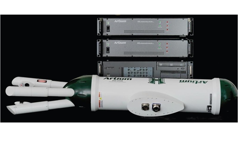
北京欧兰科技发展有限公司为您提供《激光诱导液体流动,气泡中激光诱导液体流动,动力学,气泡生成,速度场,浓度场检测方案(干涉仪)》,该方案主要用于其他中激光诱导液体流动,动力学,气泡生成,速度场,浓度场检测,参考标准--,《激光诱导液体流动,气泡中激光诱导液体流动,动力学,气泡生成,速度场,浓度场检测方案(干涉仪)》用到的仪器有激光相位多普勒干涉仪LDV,PDI,PDPA,PDA、德国LaVision PIV/PLIF粒子成像测速场仪、Artium PDI-FP 双量程可机载飞行探头
推荐专场
相关方案
更多
该厂商其他方案
更多


