


方案详情
文
Although turbulent jets have been studied extensively, one configuration that has not received much attention is the viscosity-stratified jet, wherein a turbulent jet of lower viscosity issues into a densitymatched host liquid of higher viscosity. We present
experimental data for scalar dispersion and two-dimensional velocity measurements in the axial plane of a turbulent axisymmetric jet with a Reynolds number (Re) of 2,000 issuing into a viscous host liquid at viscosity ratios (m) ranging from 1 to 55. The presence of a
strong viscosity discontinuity across the jet edge results in a significant decrease in the scalar spread rate. We attribute this to the rapid reduction in turbulence intensity and the suppression of large engulfing eddies at the jet edge. The velocity profile, on the other hand, indicates that the velocity width and mass flux reduce
with increasing m up to about 20, but then increase for higher values of m. This non-monotonic variation is explained by the growing influence of viscous stress for m>20. The scalar spread rate, the velocity spread rate, the centerline velocity decay rate, and the jet mass flux are all minimized for m20 for Re=2,000.
方案详情

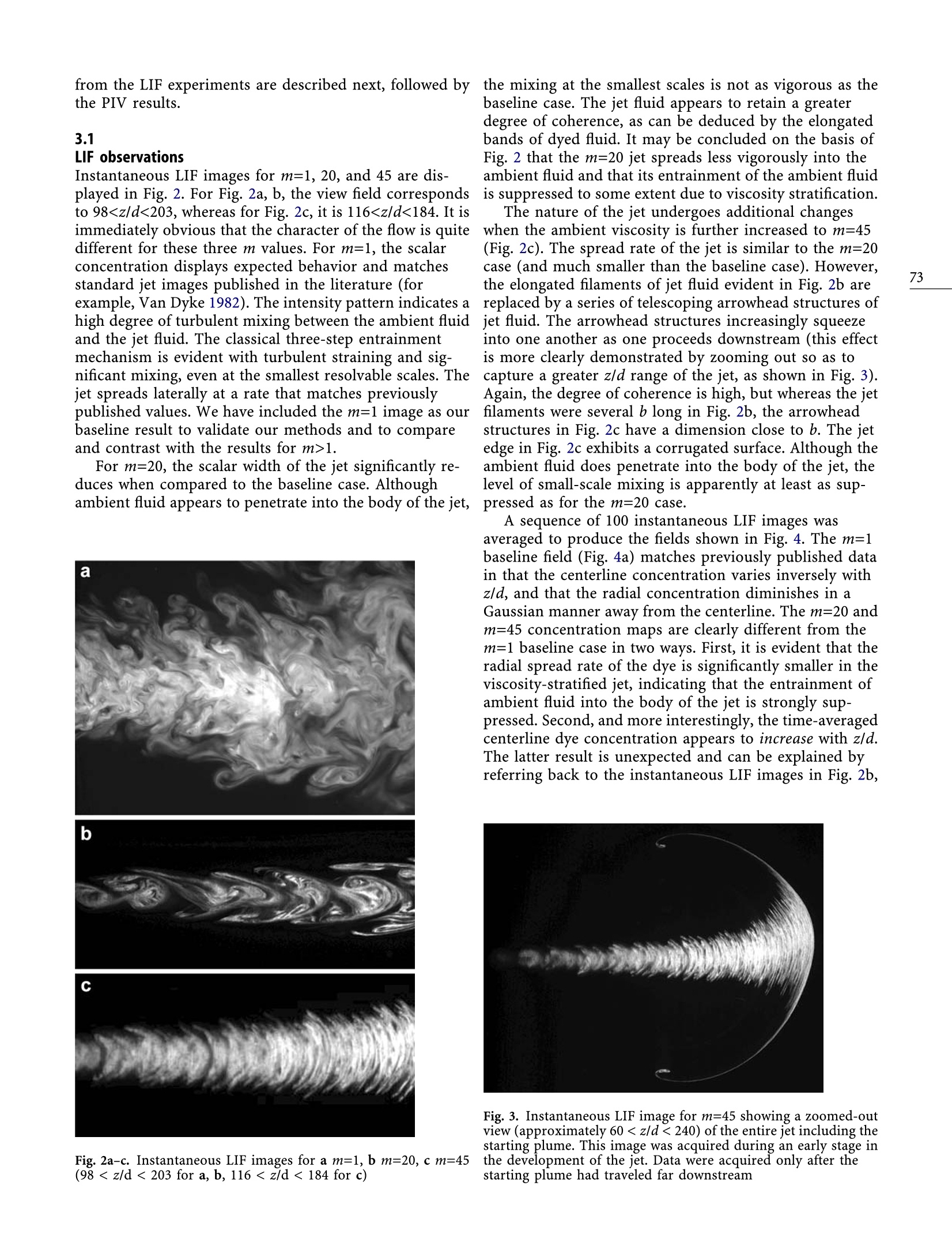
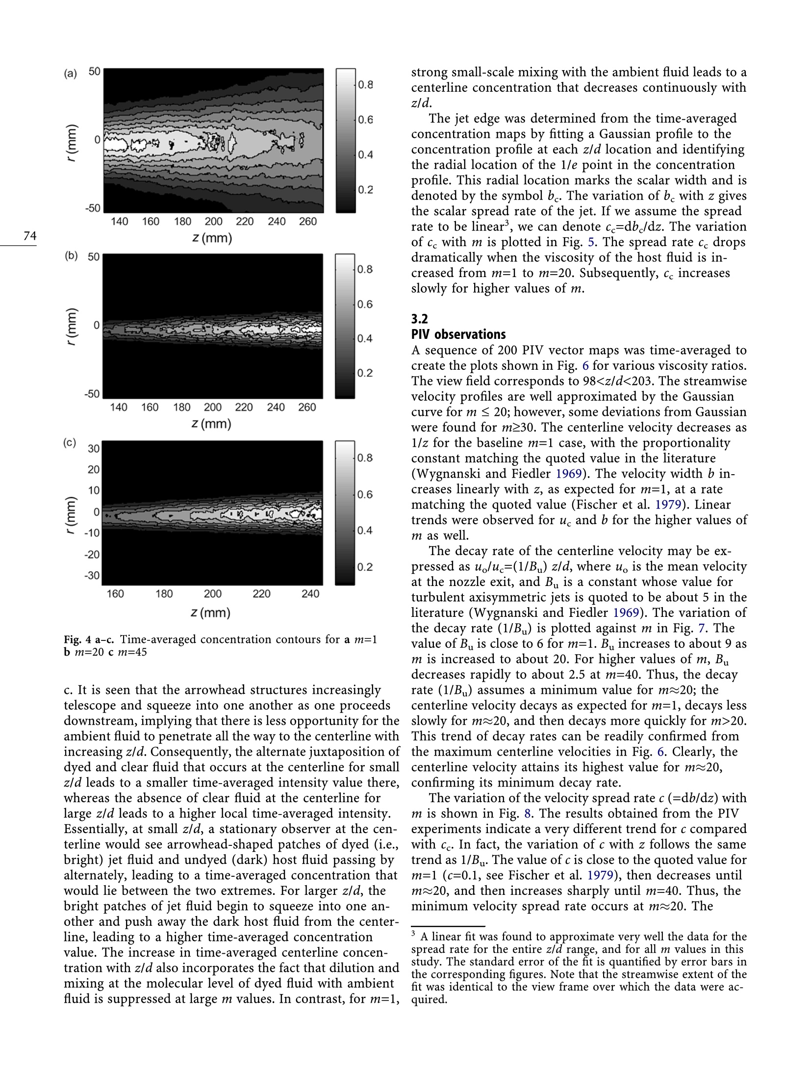
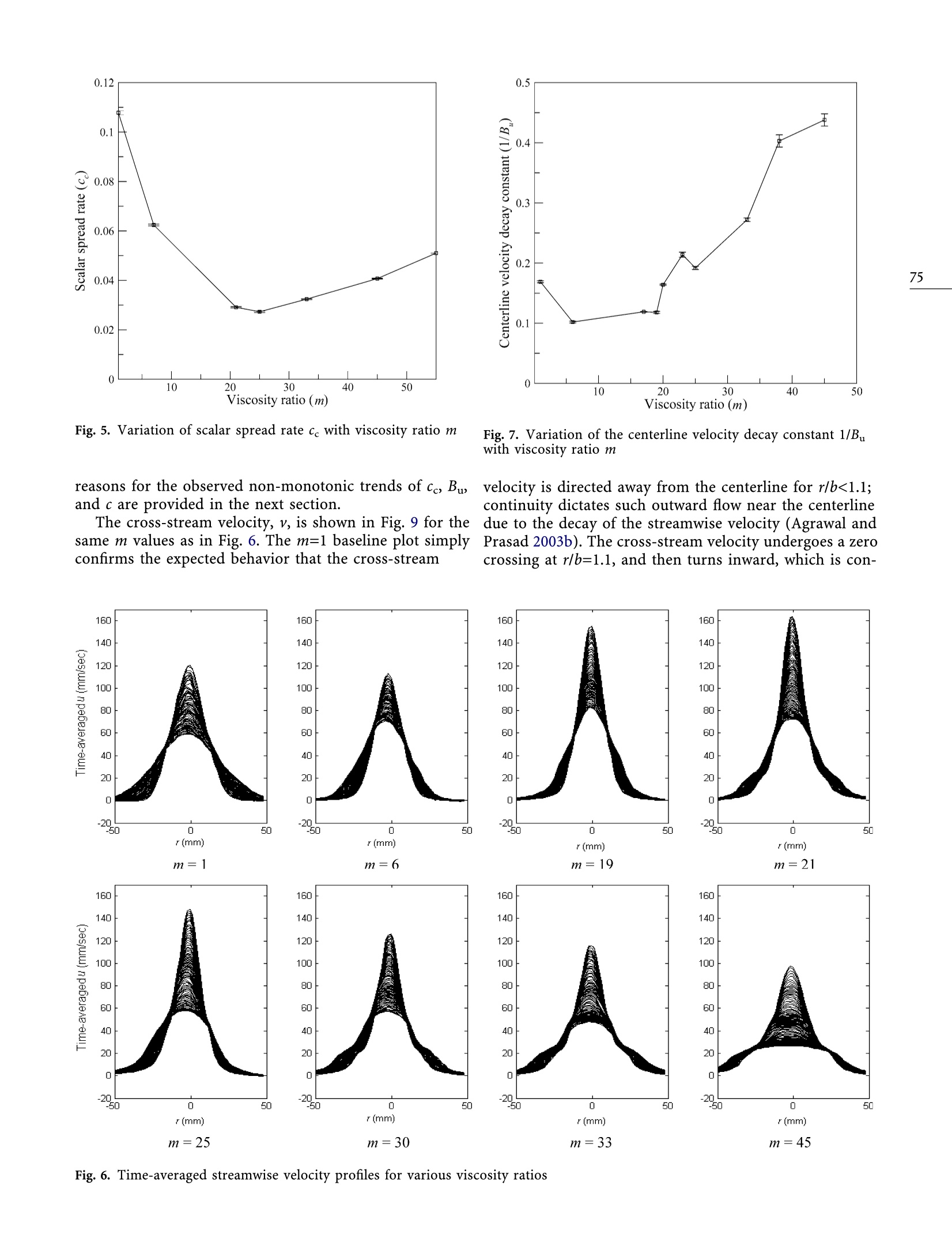
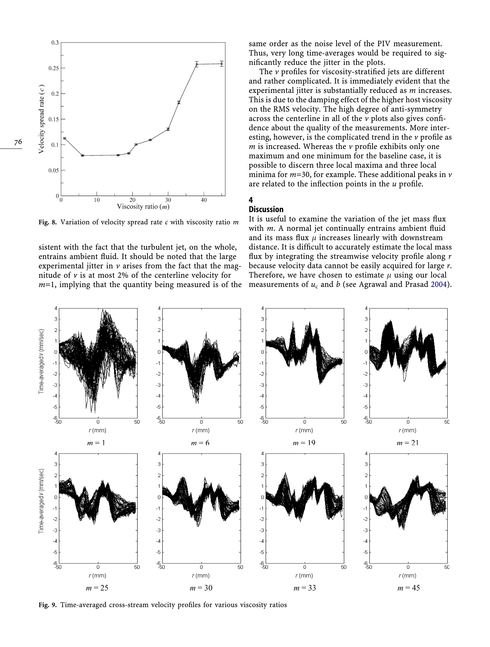
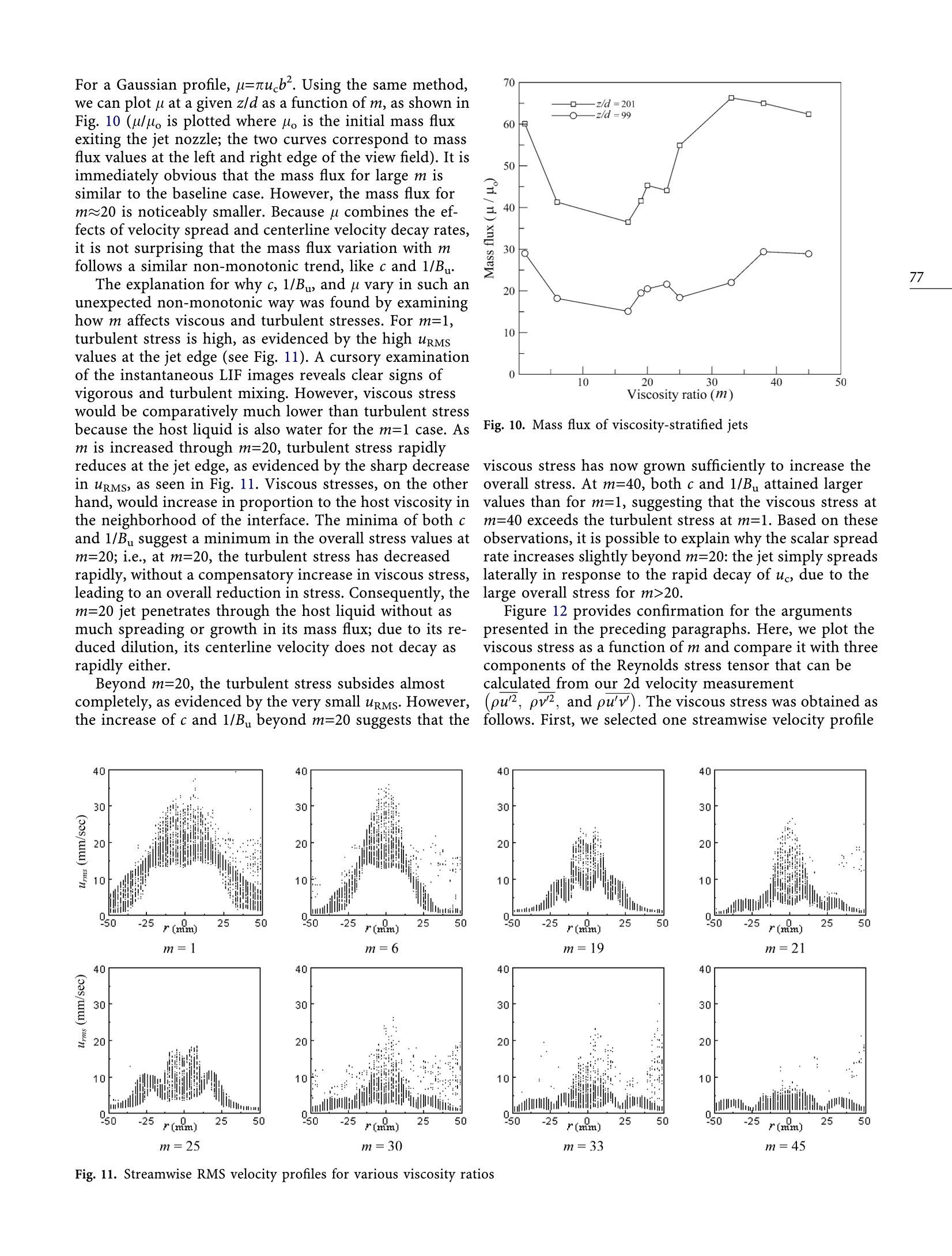
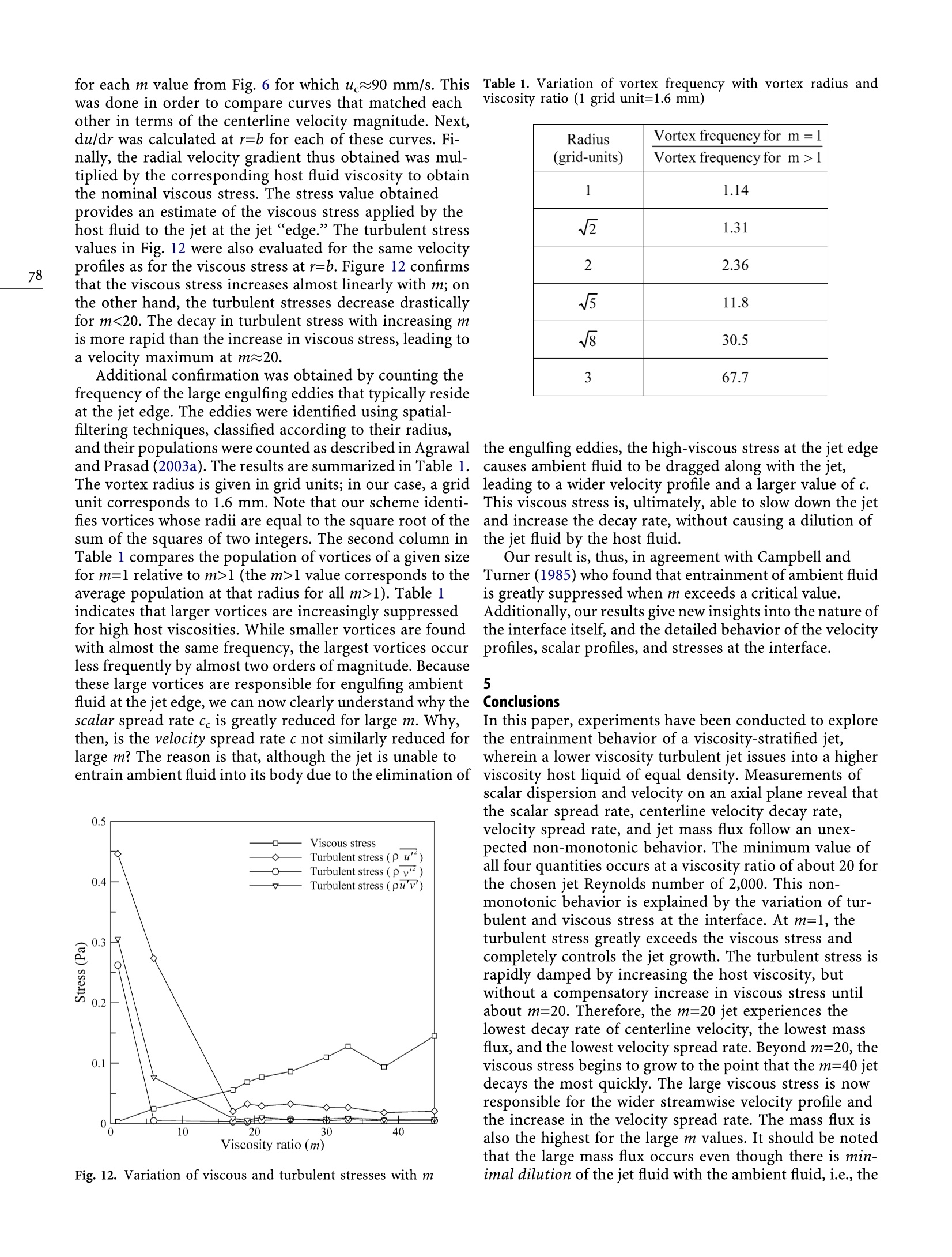
Experiments in Fluids 38 (2005) 70-79DOI 10.1007/s00348-004-0888-x70 71 The entrainment behavior of a turbulent axisymmetric jetin a viscous host fluid Sudhaker Chhabra, Thomas N. Shipman, Ajay K. Prasad Abstract Although turbulent jets have been studiedextensively, one configuration that has not receivedmuch attention is the viscosity-stratified jet, wherein aturbulent jet of lower viscosity issues into a density-matched host liquid of higher viscosity. We presentexperimental data for scalar dispersion and two-dimen-sional velocity measurements in the axial plane of aturbulent axisymmetric jet with a Reynolds number (Re)of 2,000 issuing into a viscous host liquid at viscosityratios (m) ranging from 1 to 55. The presence of astrong viscosity discontinuity across the jet edge resultsin a significant decrease in the scalar spread rate. Weattribute this to the rapid reduction in turbulenceintensity and the suppression of large engulfing eddies atthe jet edge. The velocity profile, on the other hand,indicates that the velocity width and mass flux reducewith increasing m up to about 20, but then increase forhigher values of m. This non-monotonic variation isexplained by the growing influence of viscous stress form>20. The scalar spread rate, the velocity spread rate,the centerline velocity decay rate, and the jet mass fluxare all minimized for m~20 for Re=2,000. 11 Introduction Jets belong to the class of free-shear flows and occur in alarge number of engineering and environmental situa-tions. They are driven purely by momentum supplied atthe source and are fairly simple to create, and are,therefore, frequently used as models for experimental andcomputational testing purposes. Our subject of inquiryhere is the axisymmetric turbulent jet. Specifically, we areinterested in the entrainment behavior when a density-matched, lower viscosity jet issues into a higher viscosityhost fluid. This specific multiphase configuration of tur-bulent jets has not been studied previously. Applicationsinclude the injection of hot magma into magma chambers(Campbell and Turner 1985), deep-sea hydrothermal Received: 14 May 2004 / Accepted: 21 September 2004 ( Published online: 4 November 2004 O S pringer-Verlag 2004 ) ( S. Chhabra, T.N. Shipman, A.K. Prasad(区) Department of Mechanical Engineering,University of Delaware, ) ( Newark, Deleware 19716-3140, USA ) ( E-mail:prasad@me.udel.edu ) vents where superheated water at temperatures reaching300°C issues into ambient water at about 2°℃ (corre-sponding to m~10, see Sengers and Kamgar-Parsi 1984),and industrial mixing processes. It is also known that thefuel jet in a jet diffusion flame is surrounded by fluid ofhigher viscosity, which can affect its entrainment (Takeno1994). From similarity considerations, the ordinary (m=1)axisymmetric jet spreads laterally at a linear rate, whileits centerline velocity uc varies inversely with axial dis-tance z. The time-averaged velocity and scalar concen-tration at z/d>40 are well described by a Gaussian profile.The time-averaged streamwise velocity profile may bewritten as: where b is the local jet width at the 1/e point of theGaussian profile. Turner (1986) gives uc=6.9Mz, whereM is the jet momentum and b=0.107z. The mass-flux of thejet u~Mz and du/dz=0.25M2. The entrainment rate ofthe ambient fluid into the jet is usually quantified by theentrainment coefficient o, where du/dz=2nbou. It is easyto show then, that o=0.5db/dz=0.054, and that the jetspreads with a half-angle of about 6°. The spread rate forthe scalar concentration is higher by about 20% (Turner1986). The process of entrainment in turbulent jets is under-stood to occur in three phases (Roshko 1976; Dimotakis1986). The first step, known as the induction phase, in-volves the engulfment of ambient fluid driven by the Biot-Savart-induced velocity of large vortices residing at theedge of the jet. The inducted fluid, although still irrota-tional, forms a part of the moving turbulent fluid. Sub-sequent turbulent straining of the inducted fluid reducesits spatial scale to a small enough value at which viscousdiffusion dominates (diastrophy). Finally, viscous diffu-sion enables the inducted fluid to mix at the molecularlevel with the turbulent flow (infusion). Obviously, anymechanism that interferes with the induction process willalso affect entrainment. Our current goal is to examinehow a higher viscosity ambient fluid can affect theentrainment process. The entrainment behavior of free-shear flows isinfluenced by a number of internal and externalparameters. For example, these could include densitystratification of the host fluid, buoyancy addition to thejet (both at source and off source), ambient pressure gradient, and the effect of other body forces (Sreenivasand Prasad 2000). The literature contains several in-stances of such studies (Chen and Rodi 1980). However,one aspect of turbulent entrainment that has receivedscant attention in the literature is the effect of viscositystratification across the interface between the turbulentjet flow and the ambient fluid. Our study is aimed atexamining how classical entrainment mechanisms, whichare abundantly described in the literature for ordinaryjets (Turner 1986), are affected by the introduction ofviscosity stratification between the jet and the hostfluids. The only experimental study on this topic is byCampbell and Turner (1985).Their study was motivatedby the mixing of hot, lower viscosity magma injections inmagma chambers. They injected a lower viscosity liquidof higher density vertically upwards into a tank con-taining a higher viscosity host liquid of lower density tocreate a“turbulent fountain."The injected liquid jet roseto some height into the host liquid and then fell back onitself due to its excess density. The injected fluid under-went mixing with the host fluid during its upward travelthrough the tank, and also during its bending back anddownward travel. The amount of mixing was measuredby the “filling-box method,"i.e., by noting the height towhich the mixed liquid collected in the bottom of thetank at the end of the injection period. Campbell andTurner (1985) found that, when the viscosity of the hostfluid exceeds some critical value, mixing and entrainmentare completely suppressed. Their experimental tech-niques, while highly effective for their objectives,provided only global entrainment estimates. Moreimportantly however, the turbulent fountain flow con-figuration involves an unavoidable density mismatch thatcomplicates the entrainment process. 2.1Experimental setup As shown in Fig. 1, the jet apparatus was housed within arectangular glass tank with dimensions 91.5×31×40 cm,with a horizontally oriented jet nozzle assembly mountedon one side of the tank. A simple stainless steel tube withan internal diameter of 1.33 mm acted as the nozzle. Atube length of 180 mm was chosen to ensure a fullydeveloped flow for the operating Reynolds number. Thenozzle was connected via flexible tubing, a gate valve, andflow meter to a constant head fluid source mounted on anadjustable height platform. This arrangement was used toset the desired flow rate, and, hence, the Reynolds numberfor the jet at a constant value throughout the experiment.During the experiments, the height of host fluid in theglass tank was equal to the tank width (31 cm), and thenozzle was centered on this square cross-section at oneend of the tank, as shown in Fig. 1. The dimensions of thetank relative to the jet nozzle diameter were comparable toprevious jet experiments conducted in our laboratory(Agrawal and Prasad 2002a,2002b,2003a),and ensuredthat the finiteness of the host fluid did not influence jetdevelopment in any measurable way. The jet fluid for all experimentation was de-ionizedwater. The host fluid into which the jet issued was also de-ionized water, but modified to obtain different viscositiesby adding specific amounts of sodium carboxymethylcel-lulose (NaCMC). By using a lookup table and an electronicbalance accurate to 0.1 g, appropriate amounts of NaCMCwere added to achieve desired viscosities. The preciseviscosity of the host fluid was subsequently checked usinga Physica MCR 500 rheometer. A measured amount ofThe experiment described in this paper eliminates the table sugar was added to the jet fluid to match its densitydensity difference between the injected and the host fluids. to that of the host fluid. For laser-induced fluorescenceCampbell and Turner (1985) required three parameters to (LIF) measurements, seven values of viscosity ratio (de-characterize their flow: inflow Reynolds number Re=u,d/noted as m) were chosen, including m=1, 6, 21, 25, 33, 45,v1, viscosity ratio m=v2/vi, and the internal Froude num-and 55. Nine values of m were used for particle imageber uo/(g’d)2, where u, is the input jet velocity, d is the jetvelocimetry (PIV) measurements, including m=1, 6,17, 19,orifice diameter, vi and v2 are the jet and host viscosities,21,25,33,38,and 45. Although aqueous NaCMC solutionsand g=gAplp, where p and Ap are the density of the hostL(can display shear-thinning behavior, the dilute NaCMCfluid and the excess density of the jet, respectively. In concentrations used here along with the small shear ratescontrast, matching the jet and host fluid densities simpli-ensured that the shear-thinning effects were minimal. Infies our problem to a two-parameter family (Re and m). addition, the interfacial tension between the two fluids wasNow, the turbulent fountain flow will not occur and the determined using a Kriss GmbH digital tension meterflow will revert to the simpler jet flow, albeit with viscosity(model K 10T); the corresponding Weber number (definedvariations across the jet edge. It is, thus, possible to isolateas pu b/yi, where yiis the interfacial tension) was esti-the effect of viscosity stratification and to make direct mated to be of order 10. Thus, the interfacial tension wascomparisons with the entrainment behavior for an or- not significant in our study. All measurements were con-dinary round jet, for which, a tremendous body of litera-ducted using a fully turbulent jet with Re=2,000.ture already exists. Finally,density-matching implies thatit is not necessary to orient the jet vertically. Accordingly,we have used a horizontally oriented jet in our experi-ments. 2.2Measurement techniques As shown in Fig. 1, LIF and PIV measurements wereconducted in an axial plane of the jet over a region ofinterest centered 200 mm downstream from the nozzle.The region of interest was illuminated by twin Nd-YAGlasers (Continuum Surelite II), operating at 10 Hz, andproviding 30 mJ per pulse (pulse duration=6 ns) at a ( Note, however, t h at we maintained a constant Re in the currentstudy. ) wavelength of 532 nm. The laser beams were passedthrough a sheet-forming module and steering optics toproduce a 1-mm thick vertical laser sheet that was directeddownward into the tank through the top surface, as shownin Fig. 1. A 10-bit LaVision Imager Intense PIV/LIF cam-era, with a 1,376x1,040-pixel array was oriented orthogo-nal to the illuminated plane. The camera magnificationwas set to capture a width of the jet corresponding toapproximately ±1.5b about the jet axis. For LIF measure-ments, a 140-mm wide view frame was used for m=1, 6,and 21. A 90-mm wide view field was used for all other mvalues. For PIV measurements, all view fields were set to140 mm wide. A small quantity of Rhodamine 6G dye was dissolved inthe jet fluid to conduct the LIF measurements. Whenilluminated by the Nd-YAG laser, the dye fluoresces inlinear proportion to its concentration. This linear rela-tionship was confirmed by a series of intensity tests usingdifferent (but uniform) concentrations of dye. Addition-ally, Rhodamine diffusivity is small enough" that observedintensity distributions were purely due to jet flow, and notdue to molecular diffusion. Images were captured at1 frame/s so as to ensure statistical independence betweenimages while keeping run lengths short enough to avoidcontamination of the ambient fluid with dye. At the end ofeach run, additional dye was added to the tank, and the f ( We estimate the Peclet number (=RexSc, where Sc is theSchmidt number for the diffusivity of Rhodamine) for the current flow t o be o f order 10'. ) Fig. 1. Schematic of experimental setup(dimensions are not to scale) tank was thoroughly mixed to ensure a uniform concen-tration. Then, a sequence of calibration images was re-corded.These calibration images were averaged and usedto normalize the jet images. Thus, any variation of laserintensity across the view field was filtered from the finalresults. The relative error in the intensity measurementamounted to less than 1% at the centerline. To obtain PIV data, both the host and the jet fluid wereseeded with 20-40 um fluorescent particles. The timeseparation between laser pulses was set to maximize in-plane particle displacement (reducing random error) whilestill restricting the out-of-plane particle motion toacceptable levels. Time separation values ranged from1 ms to 4 ms, depending on the viscosity ratio. The imageswere acquired at 1 double-frame/s. Cross correlation withdouble-pass grid refinement was used for the PIV pro-cessing, resulting in a final interrogation spot size of32×32 pixels with a 50% overlap. The particle displace-ment measurement error is about 0.1 pixels, which cor-responds to a relative error in the velocity measurement ofabout 1-2% at the centerline. A long-wave filter was mounted onto the camera lensfor both the LIF and PIV measurements to block the elasticscattering of laser light while allowing fluorescence to passthrough and improve the overall signal quality. 3Experimental observations LIF and PIV measurements were conducted for viscosityratios from 1 to 55, as described in Sect. 2.2. The results 3.1LIF observations Instantaneous LIF images for m=1, 20, and 45 are dis-played in Fig. 2. For Fig. 2a, b, the view field correspondsto 981. For m=20, the scalar width of the jet significantly re-duces when compared to the baseline case. Althoughambient fluid appears to penetrate into the body of the jet, Fig. 2a-c. Instantaneous LIF images for a m=1, b m=20, c m=45(98< z/d <203 for a, b, 11620.This trend of decay rates can be readily confirmed fromthe maximum centerline velocities in Fig. 6. Clearly, thecenterline velocity attains its highest value for m~20, The variation of the velocity spread rate c (=db/dz) withm is shown in Fig.8. The results obtained from the PIVexperiments indicate a very different trend for c comparedwith c. In fact, the variation of c with z follows the sametrend as 1/B. The value of c is close to the quoted value form=1 (c=0.1, see Fischer et al. 1979), then decreases untilm~20, and then increases sharply until m=40. Thus, theminimum velocity spread rate occurs at m~20. The ( A linear fit was f o und to approximate very well the data for thespread rate for t he e ntire z /d range, and f o r a l l m v a lues i n this study. The standard error of the fit is quantified by error bars in the corresponding figures. Note that the streamwise extent of thefit was identical to the view frame over which t he data were ac-quired. ) Fig.5. Variation of scalar spread rate ce with viscosity ratio m Fig.7. Variation of the centerline velocity decay constant 1/Buwith viscosity ratio m reasons for the observed non-monotonic trends of c, Bu velocity is directed away from the centerline for r/b<1.1;and c are provided in the next section. same m values as in Fig. 6. The m=1 baseline plot simplyconfirms the expected behavior that the cross-stream continuity dictates such outward flow near the centerlineThe cross-stream velocity, v, is shown in Fig. 9 for the due to the decay of the streamwise velocity (Agrawal and1Prasad 2003b). The cross-stream velocity undergoes a zerocrossing at r/b=1.1, and then turns inward, which is con- Fig. 6. Time-averaged streamwise velocity profiles for various viscosity ratios Fig. 8. Variation of velocity spread rate c with viscosity ratio m sistent with the fact that the turbulent jet, on the whole,entrains ambient fluid. It should be noted that the largeexperimental jitter in v arises from the fact that the magg.-nitude of v is at most 2% of the centerline velocity form=1, implying that the quantity being measured is of the same order as the noise level of the PIV measurement.Thus, very long time-averages would be required to sig-nificantly reduce the jitter in the plots. The v profiles for viscosity-stratified jets are differentand rather complicated. It is immediately evident that theexperimental jitter is substantially reduced as m increases.This is due to the damping effect of the higher host viscosityon the RMS velocity. The high degree of anti-symmetryacross the centerline in all of the v plots also gives confi-dence about the quality of the measurements. More inter-esting, however, is the complicated trend in the v profile asm is increased. Whereas the v profile exhibits only onemaximum and one minimum for the baseline case, it ispossible to discern three local maxima and three local1minima for m=30, for example. These additional peaks in vare related to the inflection points in the u profile. 4Discussion It is useful to examine the variation of the jet mass fluxwith m. A normal jet continually entrains ambient fluidand its mass flux u increases linearly with downstreamdistance. It is difficult to accurately estimate the local massflux by integrating the streamwise velocity profile along rbecause velocity data cannot be easily acquired for large r.Therefore, we have chosen to estimate u using our localmeasurements of uc and b (see Agrawal and Prasad 2004). Fig. 9. Time-averaged cross-stream velocity profiles for various viscosity ratios For a Gaussian profile, u=nucb’. Using the same method,we can plot p at a given z/d as a function of m, as shown inFig. 10 (uluo is plotted where uois the initial mass fluxexiting the jet nozzle; the two curves correspond to massflux values at the left and right edge of the view field). It isimmediately obvious that the mass flux for large m issimilar to the baseline case. However,the mass flux form20 is noticeably smaller. Because u combines the ef-fects of velocity spread and centerline velocity decay rates,it is not surprising that the mass flux variation with mfollows a similar non-monotonic trend, like c and 1/B.. The explanation for why c, 1/Bu, and vary in such anunexpected non-monotonic way was found by examininghow m affects viscous and turbulent stresses. For m=1,turbulent stress is high, as evidenced by the high uRMsvalues at the jet edge (see Fig.11). A cursory examinationof the instantaneous LIF images reveals clear signs ofvigorous and turbulent mixing. However, viscous stresswould be comparatively much lower than turbulent stressbecause the host liquid is also water for the m=1 case. Asm is increased through m=20, turbulent stress rapidlyreduces at the jet edge, as evidenced by the sharp decreasein uRMs, as seen in Fig. 11. Viscous stresses, on the otherhand, would increase in proportion to the host viscosity inthe neighborhood of the interface. The minima of both cCand 1/Bu suggest a minimum in the overall stress values atm=20; i.e., at m=20, the turbulent stress has decreasedrapidly, without a compensatory increase in viscous stress,leading to an overall reduction in stress. Consequently, them=20 jet penetrates through the host liquid without asmuch spreading or growth in its mass flux; due to its re-duced dilution, its centerline velocity does not decay asrapidly either. Beyond m=20, the turbulent stress subsides almostcompletely, as evidenced by the very small uRMs. However,the increase of c and 1/B beyond m=20 suggests that the Fig. 10. Mass flux of viscosity-stratified jets [ viscous stress has now grown sufficiently to increase theoverall stress. At m=40, both c and 1/Bu attained largervalues than for m=1, suggesting that the viscous stress atm=40 exceeds the turbulent stress at m=1. Based on theseobservations, it is possible to explain why the scalar spreadrate increases slightly beyond m=20: the jet simply spreadslaterally in response to the rapid decay of uc, due to thelarge overall stress for m>20. Figure 12 provides confirmation for the argumentspresented in the preceding paragraphs. Here, we plot theviscous stress as a function of m and compare it with threecomponents of the Reynolds stress tensor that can becalculated from our 2d velocity measurement e (pu2, pv2, and pu’v). The viscous stress was obtained asfollows. First, we selected one streamwise velocity profile Fig. 11. Streamwise RMS velocity profiles for various viscosity ratios for each m value from Fig. 6 for which uc~90 mm/s. Thiswas done in order to compare curves that matched eachother in terms of the centerline velocity magnitude. Next,du/dr was calculated at r=b for each of these curves. Fi-nally, the radial velocity gradient thus obtained was mul-tiplied by the corresponding host fluid viscosity to obtainthe nominal viscous stress. The stress value obtainedprovides an estimate of the viscous stress applied by thehost fluid to the jet at the jet“edge." The turbulent stressvalues in Fig. 12 were also evaluated for the same velocityprofiles as for the viscous stress at r=b. Figure 12 confirmsthat the viscous stress increases almost linearly with m;onthe other hand, the turbulent stresses decrease drasticallyfor m<20. The decay in turbulent stress with increasing mis more rapid than the increase in viscous stress, leading toa velocity maximum at m~20. Additional confirmation was obtained by counting the frequency of the large engulfing eddies that typically resideat the jet edge. The eddies were identified using spatial-filtering techniques, classified according to their radius,and their populations were counted as described in Agrawaland Prasad (2003a). The results are summarized in Table 1.The vortex radius is given in grid units; in our case, a gridunit corresponds to 1.6 mm. Note that our scheme identi-fies vortices whose radii are equal to the square root of thesum of the squares of two integers. The second column inTable 1 compares the population of vortices of a given sizefor m=1 relative to m>1 (the m>1 value corresponds to theaverage population at that radius for all m>1). Table 1indicates that larger vortices are increasingly suppressedfor high host viscosities. While smaller vortices are foundwith almost the same frequency, the largest vortices occurless frequently by almost two orders of magnitude. Becausethese large vortices are responsible for engulfing ambient 5fluid at the jet edge, we can now clearly understand why thescalar spread rate cc is greatly reduced for large m. Why,then, is the velocity spread rate c not similarly reduced for tlarge m? The reason is that, although the jet is unable to entrain ambient fluid into its body due to the elimination of v Fig. 12. Variation of viscous and turbulent stresses with m Table 1. Variation of vortex frequency with vortex radius andviscosity ratio (1 grid unit=1.6 mm) Radius(grid-units) Vortex frequency for m=1 Vortex frequency for m >1 1 1.14 2 1.31 2 2.36 5 11.8 √8 30.5 3 67.7 the engulfing eddies, the high-viscous stress at the jet edgecauses ambient fluid to be dragged along with the jet,leading to a wider velocity profile and a larger value of c.This viscous stress is, ultimately, able to slow down the jetand increase the decay rate, without causing a dilution ofthe jet fluid by the host fluid. Our result is, thus, in agreement with Campbell andTurner (1985) who found that entrainment of ambient fluidis greatly suppressed when m exceeds a critical value.Additionally, our results give new insights into the nature ofthe interface itself, and the detailed behavior of the velocityprofiles, scalar profiles, and stresses at the interface. : Conclusions In this paper, experiments have been conducted to explorethe entrainment behavior of a viscosity-stratified jet,wherein a lower viscosity turbulent jet issues into a higherviscosity host liquid of equal density. Measurements ofscalar dispersion and velocity on an axial plane reveal thatthe scalar spread rate, centerline velocity decay rate,velocity spread rate, and jet mass flux follow an unex-pected non-monotonic behavior. The minimum value ofall four quantities occurs at a viscosity ratio of about 20 forthe chosen jet Reynolds number of 2,000. This non-monotonic behavior is explained by the variation of tur-bulent and viscous stress at the interface. At m=1, theturbulent stress greatly exceeds the viscous stress andcompletely controls the jet growth. The turbulent stress israpidly damped by increasing the host viscosity, butwithout a compensatory increase in viscous stress untilabout m=20. Therefore, the m=20 jet experiences thelowest decay rate of centerline velocity, the lowest massflux, and the lowest velocity spread rate. Beyond m=20, theviscous stress begins to grow to the point that the m=40 jetdecays the most quickly. The large viscous stress is nowresponsible for the wider streamwise velocity profile andthe increase in the velocity spread rate. The mass flux isalso the highest for the large m values. It should be notedthat the large mass flux occurs even though there is min-imal dilution of the jet fluid with the ambient fluid, i.e., the jet is now comprised of an inner core of original jet fluidsurrounded by an annular coflow of the higher-viscosityambient fluid. References Agrawal A, Prasad AK (2002a) Properties of vortices in the self-sim-ilar turbulent jet. Exp Fluids 33:565-577 ( Agrawal A, Prasad AK (2002b) Organizational modes of vortices in anaxisymmetric turbulent jet. Flow Turbul Combust 68:359-377 ) ( Agrawal A, Prasad AK (2003a) Measurements within vortex cores in a turbulent j et. J Fluid Eng 125:561-568 ) ( Agrawal A, Prasad A K (2 0 03b) Integral so l utions fo r the flow profiles of turbulent jets, plumes and wakes. J Fluid Eng 125:813-822 ) ( Agrawal A, Prasad AK (2004) Evolution of a turbulent jet subjected to volumetric heating. J Fluid Mech 511:95-123 ) ( Campbell IH, Turner JS (1985) Turbulent mixing between fl u ids w i th different viscosities . Nature 313:39-42 ) ( Chen C J, Rodi W ( 1 980) Vertical t urbulent b uoyant jets-a review o f experimental data. Pergamon, Oxford, UK ) Dimotakis PE (1986) Two-dimensional shear-layer entrainment.AIAA J 24:1791-1796 Fischer HB, List EJ, Koh RCY, Imberger J, Brooks NH (1979) Mixingin inland and coastal waters. Academic Press, New York Roshko A (1976) Structure of turbulent shear flows: a new look. AIAAJ 14:1349-1357 Sengers JV, Kamgar-Parsi B (1984) Representative equations for theviscosity of water substance. J Phys Chem Ref Data 13:185-205 Sreenivas KR, Prasad AK (2000) A vortex-dynamics model forentrainment in jets and plumes. Phys Fluids 12:2101-2107 Takeno T (1994) Transition and structure of jet diffusion flames. In:Proceedings of the 25th international symposium on combustion,Irvine, California, July/August 1994. The Combustion Institute,Pittsburgh, Pennsylvania, pp 1061-1073 Turner JS (1986) Turbulent entrainment: the development of theentrainment assumption, and its application to geophysical flows.J Fluid Mech 173:431-471 Van Dyke M (1982) An album of fluid motion. Parabolic Press,Stanford,California Wygnanski I, Fiedler H (1969) Some measurements in a self-preserving jet. J Fluid Mech 38:577-612
确定

还剩8页未读,是否继续阅读?

产品配置单

北京欧兰科技发展有限公司为您提供《流体,喷射中速度场, 夹带行为检测方案(粒子图像测速)》,该方案主要用于其他中速度场, 夹带行为检测,参考标准--,《流体,喷射中速度场, 夹带行为检测方案(粒子图像测速)》用到的仪器有德国LaVision PIV/PLIF粒子成像测速场仪
推荐专场


相关方案
更多
该厂商其他方案
更多