


方案详情
文
This contribution highlights recent advances in laser diagnostics at high repetition rates. Based on
recent improvements in all-solid-state diode-pumped laser- and CMOS-camera technology, well
known methods such as Mie scattering, particle image velocimetry (PIV) or planar laser-induced
fluorescence (PLIF) are adapted and extended to repetition rates in the kHz-regime, and applied
simultaneously to a turbulent opposed jet burner. The high temporal resolution enables one to
track transient events in turbulent combustion, such as flame extinction and ignition. New
perspectives into turbulent combustion are thus possible by quasi-4D imaging or multidimensional
conditioning on transient phenomena.
方案详情

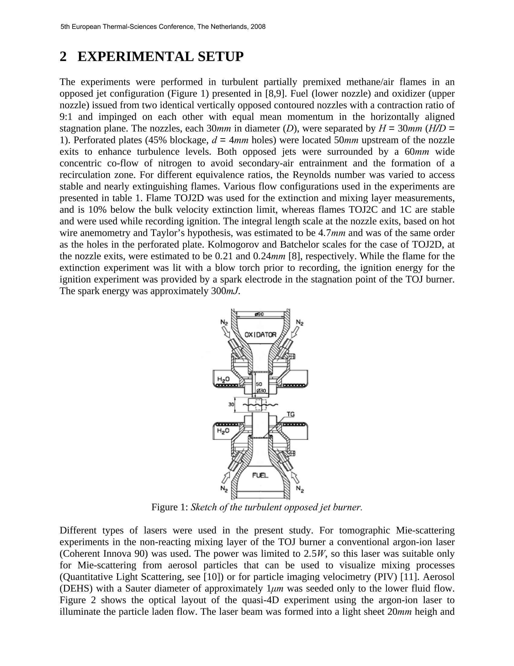
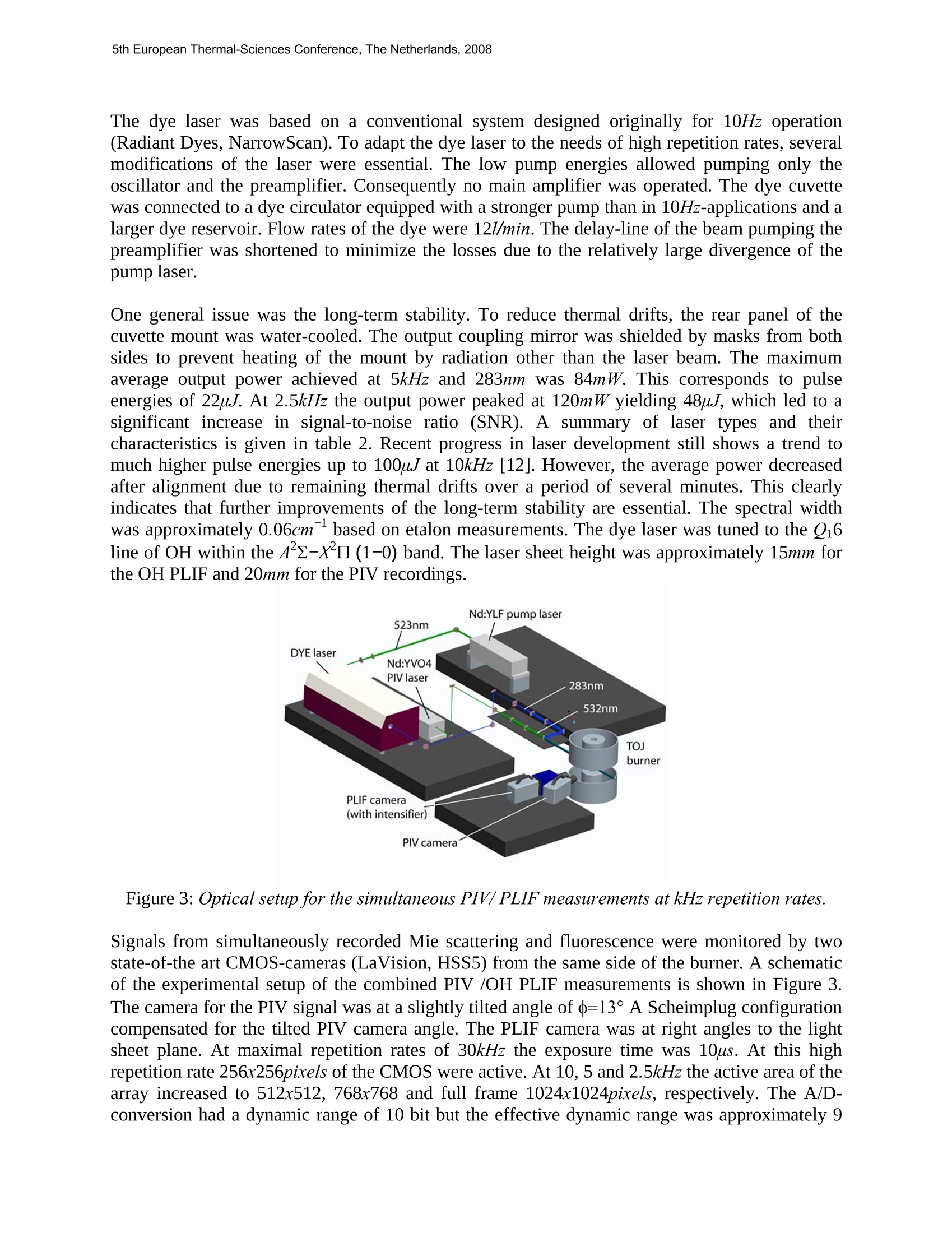
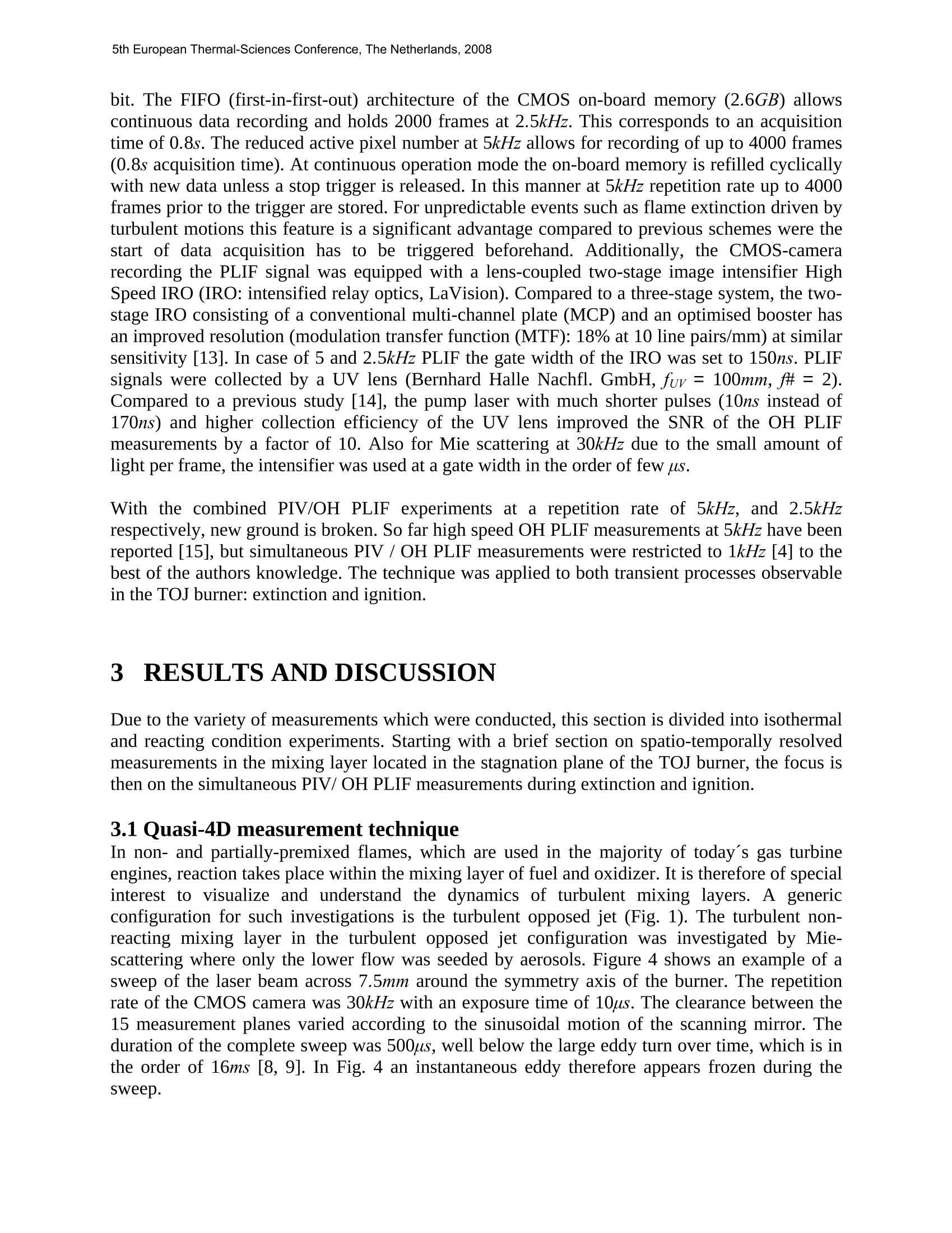
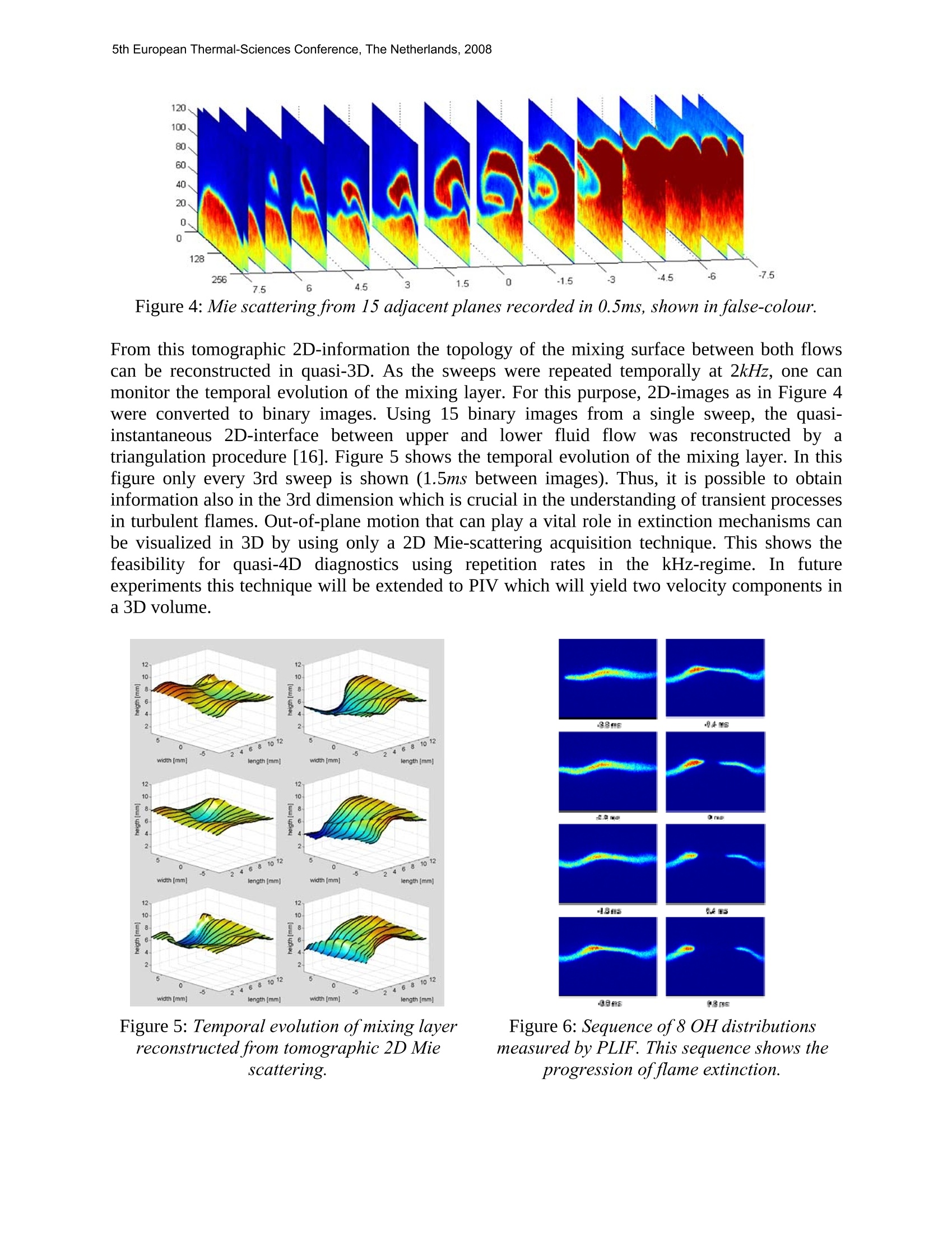
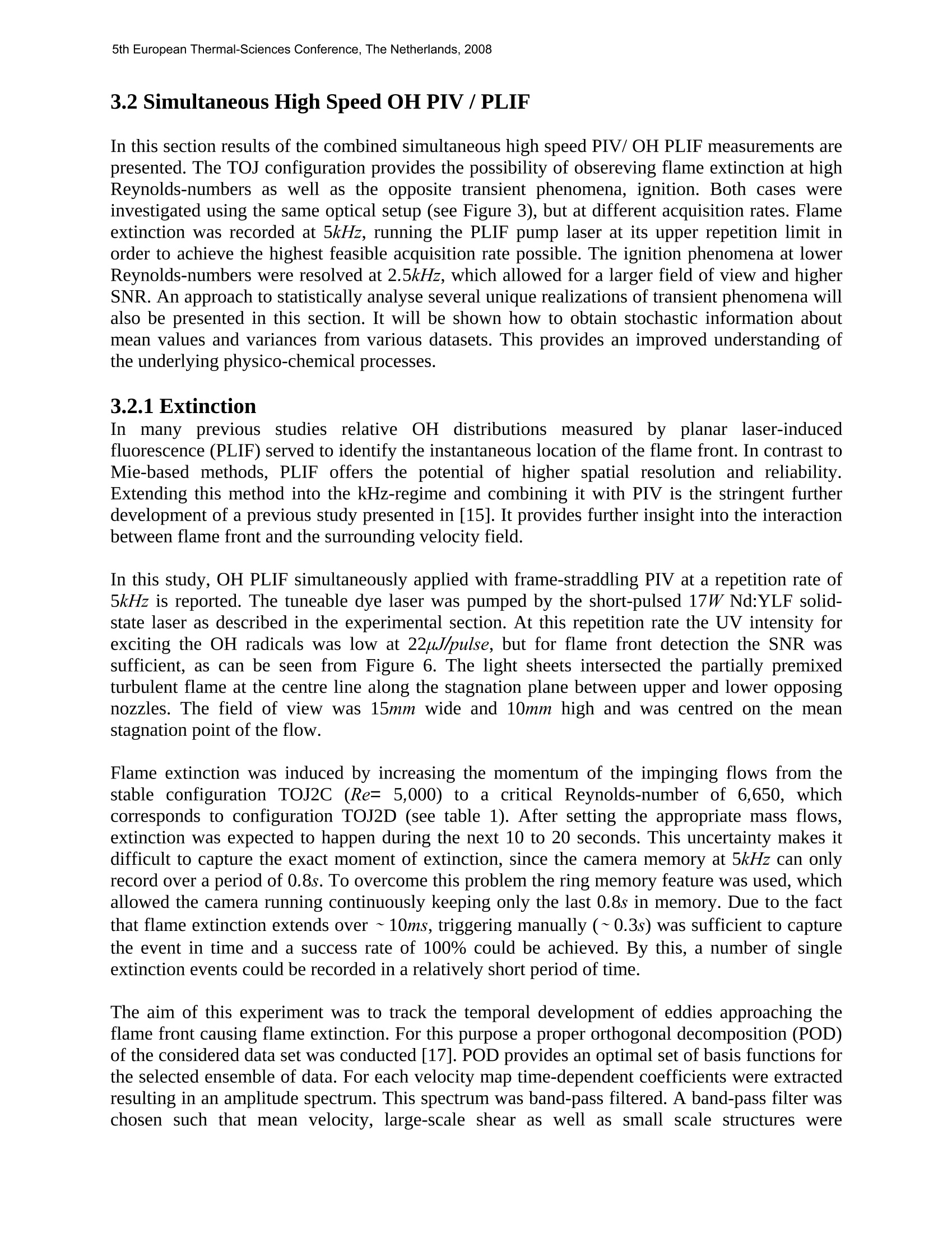
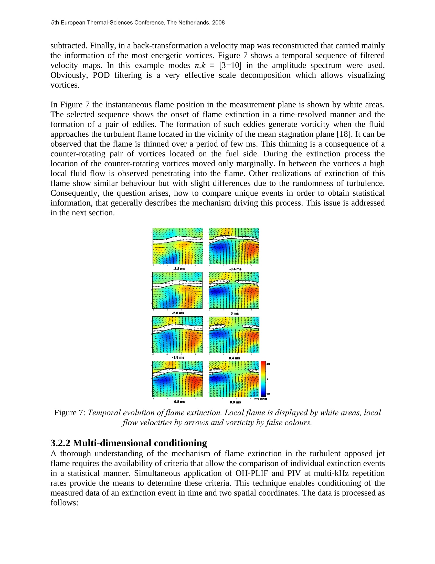
5th European Thermal-Sciences Conference, The Netherlands, 2008 PLANAR HIGH-SPEED COMBUSTION DIAGNOSTICS C. Kittler, B. Bohm, R. Gordon, A. Dreizler TU Darmstadt, FG Energie- und Kraftwerkstechnik, Darmstadt, Germany Abstract This contribution highlights recent advances in laser diagnostics at high repetition rates. Based onrecent improvements in all-solid-state diode-pumped laser- and CMOS-camera technology, wellknown methods such as Mie scattering, particle image velocimetry (PIV) or planar laser-inducedfluorescence (PLIF) are adapted and extended to repetition rates in the kHz-regime, and appliedsimultaneously to a turbulent opposed jet burner. The high temporal resolution enables one totrack transient events in turbulent combustion, such as flame extinction and ignition. Newperspectives into turbulent combustion are thus possible by quasi-4D imaging or multi-dimensional conditioning on transient phenomena. 1Introduction Present understanding of turbulent combustion processes is based partly on non-intrusive opticaldiagnostics methods. Over the last three decades a variety of different diagnostics weredeveloped and applied to study flow and scalar fields of very different flames spanning fromgeneric to practical. The advent of sensitive CCD cameras allowed researchers to measureinstantaneous spatial distributions of different flow and scalar quantities. Spatial gradients andcorrelations became accessible in addition to “single-point-statistics(mean and variances ofvelocity components, temperature or chemical species concentrations). Until recently these planardiagnostics were restricted to sampling rates much slower than typical turbulent time-scales. Thisresulted in statistically uncorrelated information. Inherently transient processes such as flameextinction, ignition or flashback and their associated temporal correlations were not accessible bythese low repetition rates. Recent developments in all-solid-state diode-pumped laser (DPSS) and high frame rate CMOS-camera technology enable the advancement of combustion diagnostics towards temporallysequential, three-dimensional data acquisition (quasi 4D). In particular, transient events can betracked in a cinematographic manner over sufficiently long periods to study temporal evolutionsin turbulent flames from a very different perspective [1-5]. In contrast to earlier studies whichused Nd:YAG-laser and ICCD-camera clusters [6], the structure of the CMOS on-board memoryallows one to release a trigger after an event (such as flame extinction or auto-ignition offlammable mixtures) has occurred. In this manner data-sequences recorded prior to the trigger arestored. In contrast to previous technology, the success rate of recording essential time-intervals isincreased to virtually 100% and data-sequences consist of up to several thousand frames. In this review simultaneous particle image velocimetry (PIV) and OH-radical planar laser-induced fluorescence (PLIF) measurements with repetition rates up to 5 kHz are presented. Whenapplied to transient phenomena such as extinction, ignition [6,7] or flashback, it is shown thatthese measurements enable a perspective on complex interactions between turbulent flows andchemical reactions that is very different from statistically uncorrelated sampling. 2EXPERIMENTAL SETUP The experiments were performed in turbulent partially premixed methane/air flames in anopposed jet configuration (Figure 1) presented in [8,9]. Fuel (lower nozzle) and oxidizer (uppernozzle) issued from two identical vertically opposed contoured nozzles with a contraction ratio of9:1 and impinged on each other with equal mean momentum in the horizontally alignedstagnation plane. The nozzles, each 30mm in diameter (D), were separated by H= 30mm (H/D=1). Perforated plates (45% blockage, d=4mm holes) were located 50mm upstream of the nozzleexits to enhance turbulence levels. Both opposed jets were surrounded by a 60mm wideconcentric co-flow of nitrogen to avoid secondary-air entrainment and the formation of arecirculation zone. For different equivalence ratios, the Reynolds number was varied to accessstable and nearly extinguishing flames. Various flow configurations used in the experiments arepresented in table 1. Flame TOJ2D was used for the extinction and mixing layer measurements,and is 10% below the bulk velocity extinction limit, whereas flames TOJ2C and 1C are stableand were used while recording ignition. The integral length scale at the nozzle exits, based on hotwire anemometry and Taylor’s hypothesis, was estimated to be 4.7mm and was of the same orderas the holes in the perforated plate. Kolmogorov and Batchelor scales for the case of TOJ2D, atthe nozzle exits, were estimated to be 0.21 and 0.24mm [8], respectively. While the flame for theextinction experiment was lit with a blow torch prior to recording, the ignition energy for theignition experiment was provided by a spark electrode in the stagnation point of the TOJ burner.The spark energy was approximately 300mJ. Figure 1: Sketch of the turbulent opposed jet burner. Different types of lasers were used in the present study. For tomographic Mie-scatteringexperiments in the non-reacting mixing layer of the TOJ burner a conventional argon-ion laser(Coherent Innova 90) was used. The power was limited to 2.5W, so this laser was suitable onlyfor Mie-scattering from aerosol particles that can be used to visualize mixing processes(Quantitative Light Scattering, see [10]) or for particle imaging velocimetry (PIV) [11]. Aerosol(DEHS) with a Sauter diameter of approximately lum was seeded only to the lower fluid flow.Figure 2 shows the optical layout of the quasi-4D experiment using the argon-ion laser toilluminate the particle laden flow. The laser beam was formed into a light sheet 20mm heigh and 1mm wide. The beam was scanned across the probe volume by a galvanic mirror (GSILumonics). The maximum scan rate per sweep was 2kHz. Multiple tomographic 2D planes weremonitored successively over a range of 15mm. The depth of field of the camera lens was adaptedto this range. The field of view in this case was 12x12mm. Table 1 Operational conditions for differentflames. Table 2 Specifications of various lasers used inthis study. 一 kHz] TOJ2D power [W] TOJ2C length [ns] TOJID pulse energy [mJ] Re 6.650 5.000 6,650 0.7 币 2.0 2.0 3.18 3.4 Bulk velocity [ms-1] 3.4 2.55 3.4 3.4 Bulk strain rate [s-1] 231 175 175 0.022 Residence time [ms] 4.3 5.7 5.7 0.048 Ar-Ion CW 2.5 The Mie scattering from solid particles was used for the high-speed PIV evaluations of thecombined PIV/PLIF measurements of the extinction experiments, and the Mie scattering fromaerosol droplets was used for the PIV of the ignition experiments. Two independently controlleddiode-pumped frequency-doubled Nd:YVO4 slab lasers in one housing, that were flexible ingenerating double pulses, were used for these experiments (EdgeWave, IS4II-DE). The Q-switched edge-pumped slab design is capable of yielding 21.3W each at repetition rates up to32.5kHz and 8.5ns pulse duration, but the experiment was limited by the maximum repetition rateof the simultaneously running PLIF pump laser to 5kHz. Figure 2: Experimental setup for quasi-4D measurements using Mie scattering. For the laser-induced fluorescence of radicals relevant to combustion processes such as hydroxyl(OH), tuneable radiation in the ultraviolet spectral range is required. For this purpose afrequency-doubled diode-pumped Nd:YLF slab laser (Edge-Wave, IS 8II-E, 523nm) was used topumpatuneable dye laser at:5kHz(extinction measurements)and2.5kHz(ignitionmeasurements) repetition rates. The Q-switched edge-pumped slab design yielded up to 17.5W at5kHz. This corresponded to single-pulse energies of 3.4mJ. The pulse length was 8.8ns, which, inconnection with a smooth beam profile, is favourable for frequency-doubling. The dye laser was based on a conventional system designed originally for 10Hz operation(Radiant Dyes, NarrowScan). To adapt the dye laser to the needs of high repetition rates, severalmodifications of the laser were essential. The low pump energies allowed pumping only theoscillator and the preamplifier. Consequently no main amplifier was operated. The dye cuvettewas connected to a dye circulator equipped with a stronger pump than in 10Hz-applications and alarger dye reservoir. Flow rates of the dye were 12l/min. The delay-line of the beam pumping thepreamplifier was shortened to minimize the losses due to the relatively large divergence of thepump laser. One general issue was the long-term stability. To reduce thermal drifts, the rear panel of thecuvette mount was water-cooled. The output coupling mirror was shielded by masks from bothsides to prevent heating of the mount by radiation other than the laser beam. The maximumaverage output power achieved at 5kHz and 283nm was 84mW. This corresponds to pulseenergies of 22pJ. At 2.5kHz the output power peaked at 120mW yielding 48pJ, which led to asignificant increase in signal-to-noise ratio (SNR). A summary of laser types and theircharacteristics is given in table 2. Recent progress in laser development still shows a trend tomuch higher pulse energies up to 100pJ at 10kHz [12]. However, the average power decreasedafter alignment due to remaining thermal drifts over a period of several minutes. This clearlyindicates that further improvements of the long-term stability are essential. The spectral widthwas approximately 0.06cm based on etalon measurements. The dye laser was tuned to the Q16line of OH within the A2-XII (1-0) band. The laser sheet height was approximately 15mm forthe OH PLIF and 20mm for the PIV recordings. Figure 3: Optical setup for the simultaneous PIV/ PLIF measurements at kHz repetition rates. Signals from simultaneously recorded Mie scattering and fluorescence were monitored by twostate-of-the art CMOS-cameras (LaVision, HSS5) from the same side of the burner. A schematicof the experimental setup of the combined PIV /OH PLIF measurements is shown in Figure 3.The camera for the PIV signal was at a slightly tilted angle of 0=13° A Scheimplug configurationcompensated for the tilted PIV camera angle. The PLIF camera was at right angles to the lightsheet plane. At maximal repetition rates of 30kHz the exposure time was 10us. At this highrepetition rate 256x256pixels of the CMOS were active. At 10,5 and 2.5kHz the active area of thearray increased to 512x512, 768x768 and full frame 1024x1024pixels, respectively. The A/D-conversion had a dynamic range of 10 bit but the effective dynamic range was approximately 9 bit. The FIFO (first-in-first-out) architecture of the CMOS on-board memory (2.6GB) allowscontinuous data recording and holds 2000 frames at 2.5kHz. This corresponds to an acquisitiontime of 0.8s. The reduced active pixel number at 5kHz allows for recording of up to 4000 frames(0.8s acquisition time). At continuous operation mode the on-board memory is refilled cyclicallywith new data unless a stop trigger is released. In this manner at 5kHz repetition rate up to 4000frames prior to the trigger are stored. For unpredictable events such as flame extinction driven byturbulent motions this feature is a significant advantage compared to previous schemes were thestart of data acquisition has to be triggered beforehand. Additionally, the CMOS-camerarecording the PLIF signal was equipped with a lens-coupled two-stage image intensifier HighSpeed IRO (IRO: intensified relay optics, LaVision). Compared to a three-stage system, the two-stage IRO consisting of a conventional multi-channel plate (MCP) and an optimised booster hasan improved resolution (modulation transfer function (MTF): 18% at 10 line pairs/mm) at similarsensitivity [13]. In case of 5 and 2.5kHz PLIF the gate width of the IRO was set to 150ns. PLIFsignals were collected by a UV lens (Bernhard Halle Nachfl. GmbH, fuv = 100mm,f#=2).Compared to a previous study [14], the pump laser with much shorter pulses (10ns instead of170ns) and higher collection efficiency of the UV lens improved the SNR of the OH PLIFmeasurements by a factor of 10. Also for Mie scattering at 30kHz due to the small amount oflight per frame, the intensifier was used at a gate width in the order of few us. With the combined PIV/OH PLIF experiments at a repetition rate of 5kHz, and 2.5kHzrespectively, new ground is broken. So far high speed OH PLIF measurements at 5kHz have beenreported [15], but simultaneous PIV / OH PLIF measurements were restricted to 1kHz [4] to thebest of the authors knowledge. The technique was applied to both transient processes observablein the TOJ burner: extinction and ignition. 3RESULTS AND DISCUSSION Due to the variety of measurements which were conducted, this section is divided into isothermaland reacting condition experiments. Starting with a brief section on spatio-temporally resolvedmeasurements in the mixing layer located in the stagnation plane of the TOJ burner, the focus isthen on the simultaneous PIV/ OH PLIF measurements during extinction and ignition. 3.1 Quasi-4D measurement technique In non- and partially-premixed flames, which are used in the majority of today’s gas turbineengines, reaction takes place within the mixing layer of fuel and oxidizer. It is therefore of specialinterest to visualize and understand the dynamics of turbulent mixing layers. A genericconfiguration for such investigations is the turbulent opposed jet (Fig. 1). The turbulent non-reacting mixing layer in the turbulent opposed jet configuration was investigated by Mie-scattering where only the lower flow was seeded by aerosols. Figure 4 shows an example of asweep of the laser beam across 7.5mm around the symmetry axis of the burner. The repetitionrate of the CMOS camera was 30kHz with an exposure time of 10us. The clearance between the15 measurement planes varied according to the sinusoidal motion of the scanning mirror. Theduration of the complete sweep was 500us, well below the large eddy turn over time, which is inthe order of 16ms [8, 9]. In Fig. 4 an instantaneous eddy therefore appears frozen during thesweep. Figure 4: Mie scattering from 15 adjacent planes recorded in 0.5ms, shown in false-colour. From this tomographic 2D-information the topology of the mixing surface between both flowscan be reconstructed in quasi-3D. As the sweeps were repeated temporally at 2kHz, one canmonitor the temporal evolution of the mixing layer. For this purpose, 2D-images as in Figure 4were converted to binary images. Using 15 binary images from a single sweep, the quasi-instantaneousS2D-interface between upper and lower fluid flowwas reconstructed by atriangulation procedure [16]. Figure 5 shows the temporal evolution of the mixing layer. In thisfigure only every 3rd sweep is shown (1.5ms between images). Thus, it is possible to obtaininformation also in the 3rd dimension which is crucial in the understanding of transient processesin turbulent flames. Out-of-plane motion that can play a vital role in extinction mechanisms canbe visualized in 3D by using only a 2D Mie-scattering acquisition technique. This shows thefeasibility for quasi-4D diagnostics using repetition ratesin the kHz-regime. In futureexperiments this technique will be extended to PIV which will yield two velocity components ina 3D volume. Figure 5: Temporal evolution ofmixing layerreconstructed from tomographic 2D Miescattering. Figure 6: Sequence of 8 OH distributionsmeasured by PLIF. This sequence shows theprogression of flame extinction. 3.2 Simultaneous High Speed OH PIV/PLIF In this section results of the combined simultaneous high speed PIV/ OH PLIF measurements arepresented. The TOJ configuration provides the possibility of obsereving flame extinction at highReynolds-numbers as well as the opposite transient phenomena, ignition. Both cases wereinvestigated using the same optical setup (see Figure 3), but at different acquisition rates. Flameextinction was recorded at 5kHz, running the PLIF pump laser at its upper repetition limit inorder to achieve the highest feasible acquisition rate possible. The ignition phenomena at lowerReynolds-numbers were resolved at 2.5kHz, which allowed for a larger field of view and higherSNR. An approach to statistically analyse several unique realizations of transient phenomena willalso be presented in this section. It will be shown how to obtain stochastic information aboutmean values and variances from various datasets. This provides an improved understanding ofthe underlying physico-chemical processes. 3.2.1 Extinction In1 many previousstudies relative OH distributions measured by planar laser-inducedfluorescence (PLIF) served to identify the instantaneous location of the flame front. In contrast toMie-based methods, PLIF offers the potential of higher spatial resolution and reliability.Extending this method into the kHz-regime and combining it with PIV is the stringent furtherdevelopment of a previous study presented in [15]. It provides further insight into the interactionbetween flame front and the surrounding velocity field. In this study, OH PLIF simultaneously applied with frame-straddling PIV at a repetition rate of5kHz is reported. The tuneable dye laser was pumped by the short-pulsed 17W Nd:YLF solid-state laser as described in the experimental section. At this repetition rate the UV intensity forexciting the OH radicals was low at 22pJ/pulse, but for flame front detection the SNR wassufficient, as can be seen from Figure 6. The light sheets intersected the partially premixedturbulent flame at the centre line along the stagnation plane between upper and lower opposingnozzles. The field of view was 15mm wide and 10mm high and was centred on the meanstagnation point of the flow. Flame extinction was induced by increasing the momentum of the impinging flows from thestable configuration TOJ2C (Re= 5,000) to a critical Reynolds-number of 6,650, whichcorresponds to configuration TOJ2D (see table 1). After setting the appropriate mass flows,extinction was expected to happen during the next 10 to 20 seconds. This uncertainty makes itdifficult to capture the exact moment of extinction, since the camera memory at 5kHz can onlyrecord over a period of 0.8s. To overcome this problem the ring memory feature was used, whichallowed the camera running continuously keeping only the last 0.8s in memory. Due to the factthat flame extinction extends over ~10ms, triggering manually (~0.3s) was sufficient to capturethe event in time and a success rate of 100% could be achieved. By this, a number of singleextinction events could be recorded in a relatively short period of time. The aim of this experiment was to track the temporal development of eddies approaching theflame front causing flame extinction. For this purpose a proper orthogonal decomposition (POD)of the considered data set was conducted [17]. POD provides an optimal set of basis functions forthe selected ensemble of data. For each velocity map time-dependent coefficients were extractedresulting in an amplitude spectrum. This spectrum was band-pass filtered. A band-pass filter waschosen such that mean velocity, large-scale shear as well as small scale structures were subtracted. Finally, in a back-transformation a velocity map was reconstructed that carried mainlythe information of the most energetic vortices. Figure 7 shows a temporal sequence of filteredvelocity maps. In this example modes n,k = [3-10] in the amplitude spectrum were used.Obviously, POD filtering is a very effective scale decomposition which allows visualizingvortices. In Figure 7 the instantaneous flame position in the measurement plane is shown by white areas.The selected sequence shows the onset of flame extinction in a time-resolved manner and theformation of a pair of eddies. The formation of such eddies generate vorticity when the fluidapproaches the turbulent flame located in the vicinity of the mean stagnation plane [18]. It can beobserved that the flame is thinned over a period of few ms. This thinning is a consequence of acounter-rotating pair of vortices located on the fuel side. During the extinction process thelocation of the counter-rotating vortices moved only marginally. In between the vortices a highlocal fluid flow is observed penetrating into the flame. Other realizations of extinction of thisflame show similar behaviour but with slight differences due to the randomness of turbulence.Consequently, the question arises, how to compare unique events in order to obtain statisticalinformation, that generally describes the mechanism driving this process. This issue is addressedin the next section. Figure 7: Temporal evolution of flame extinction. Local flame is displayed by white areas, localflow velocities by arrows and vorticity by false colours. 3.2.2 Multi-dimensional conditioning A thorough understanding of the mechanism of flame extinction in the turbulent opposed jetflame requires the availability of criteria that allow the comparison of individual extinction eventsin a statistical manner. Simultaneous application of OH-PLIF and PIV at multi-kHz repetitionrates provide the means to determine these criteria. This technique enables conditioning of themeasured data of an extinction event in time and two spatial coordinates. The data is processed asfollows: Step 1: For each individual extinction event the first frame where the flame (marked by the OH-contour) breached is set to zero in time. Step 2: The origin of the radial coordinate r is shifted to the centre of the flame gap (r). Step 3: Finally, the axial coordinate is fixed to the lower OH-contour at r*= 0 for each time step,thus enabling the quantification of the flow field characteristics in the local reference frame of theflame itself. The resulting shift to conditioned spatial coordinates at conditioned time t*=0 can be seen inFigure 8. With multidimensional conditioning in space and time, a rigorous statistical analysis offlow quantities at the point of extinction is possible. Figure 9 shows results from 8 conditionedand averaged flame extinction events. The absolute strain at the origin of the conditionedcoordinate system is plotted against the conditioned time. The extinction event is seen to beginapproximately 4ms before the flame is fully breached. This time scale is in good agreement withthe previously estimated residence time of the flow in the stagnation region of this flame. It wasseen that during extinction events, turbulent vortices immediately above and below the flametended to be aligned. Pairs of counter-rotating vortices form below and/or above the flame andconvect toward the reaction zone. Through the expansion of hot gas at the flame front the vorticesdistort and accelerate. Thus, they linger in approximately the same spatial location as theirvorticity rapidly increases. This results in a continuously increasing absolute strain at the reactionzone and is seen to reach a maximum approximately 0.5ms before the flame is breached. It isinteresting to note, not all breaches in the flame result in global extinction. Occasionally,particularly when the breach occurs significantly away from the central axis of the flame, thebreach will convect outwards in radial direction but the flame re-establishes itself along thecentreline. Figure 8: Depiction of conditional coordinates. Figure 9: Averaged (closed symbols) andindividual absolute strain monitored at theorigin of the new conditional coordinate system. 3.2.3 Ignition The transition from spark plasma to a flame kernel is of major importance in the ignition processof various combustion systems. After the reaction has started in a limited location the flame hasto stabilise itself in the flow. This important aspect in the change-over from an isothermal flow toa stable burning flame is addressed in this section of the paper. The experiments are motivated to describe the path and the propagation speed of the flame through the mixing layer of the TOJburner after a flame kernel has developed. In a first attempt this is recorded by PIV usingevaporating aerosol droplets and will be supplemented by mixture fraction measurements infuture experiments. Figure 10: Sequence ofraw images showing the transition to a self-sustaining turbulent flame byedge flame propagation. Left: OH PLIF, right: Mie scattering from aerosol. For the ignition experiments a spark ignition device (from Cambridge University) with arcduration of 200us and 300mJ spark energy was positioned at different locations (centred and off-axis) within the mixing layer between the two opposing nozzles. The chemically inert MgOparticles were replaced by oil droplets and double pulses from the Nd:YVO4 laser with a pulse-to-pulse separation of 100us were generated at an overall repetition rate of 2.5kHz. The data post-processing was based on a PIV-algorithm presented in [18]. Interrogation areas of 16x16pixelcorresponded to 400x400um in the measurement plane. The OH PLIF system was simultaneously operated at 2.5kHz. Reducing the repetition rate by afactor of two resulted in an UV pulse energy of 48uJ (see table 2), which is twice as muchcompared to the 5kHz operation mode. The sensitive image intensifier (HS-IRO) was protectedfrom the spark by delaying the acquisition by △t =1ms. Additionally, the field of view wasshifted by r=4mm. A single realization of the flame ignition is shown in Figure 10. The fuel-airmixture between the nozzles is ignited at the right hand side, 4mm off-axis in the stagnationplane. The cross marks the stagnation point and the star the location of the spark. Thisexperiments show that flame front tracking by OH and evaporating droplets results in differentspatial positions. From Figure 10 can be seen that this displacement is in the order of 0.5-1mm.Since the spatial offset between OH contour and evaporating droplets is constant, the latter can still be used to measure large structures of the flame front topology. Also, an evaluation oftemporally-resolved flame tip propagation speed is possible. The Mie-scattering of the droplets inthe cold gas can be used simultaneously to process the instantaneous two-component velocityfield. Analysis of individual transitions from initial flame kernels to fully developed turbulent flamesexhibits an acceleration of the flame tip during the progression. A preliminary analysis shows,that this acceleration occurs mainly due to the convection of the bulk opposed flow, rather thanincreasing burning rates. In near future a statistical analysis of hundreds of single realizations atdifferent Reynolds-numbers and equivalent ratios will be performed based on the earlierpresented multi-dimensional conditioning to obtain information about ignition mechanisms inpartially premixed and non-premixed combustion systems. 4 CONCLUSIONS This paper demonstrates the simultaneous application of different optical diagnostic methods atrepetition rates in the kHz-regime. For the selected examples the temporal resolution was shortenough to resolve flow and flame dynamics at least of the larger scales. It was demonstrated thatby rapid scanning of a measurement plane quasi-4D information can be gained. Furthermoretransient events such as ignition and extinction can be investigated by simultaneous high speedPIV/OH PLIF and thereby tracked temporally over thousands of frames. Parts of the completesequence can be selected to extract information on flow field or scalar properties of the flow priorto and during the occurrence of transient events. This selection can be referred to as "multi-dimensional conditioning” on transient event. These high-speed diagnostics complement theresearch on turbulent flames that has been investigated mainly with statistically independentsampling. ACKNOWLEDGMENTS Financial support by Sonderforschungsbereich 568, projects A4 and B1, Graduiertenkolleg1344/1 and DFG-project DR 374/6-1 is kindly acknowledged. This work was conducted in partin cooperation with I. Boxx (DLR Stuttgart), W. Meier (DLR Stuttgart), S.F. Ahmed (UCAM)and E. Mastorakos (UCAM). REFERENCES [1]Fajardo, C. M., Smith, J. D., and Sick, V., 2006, Sustained simultaneous high-speedimaging of scalar and velocity fields using a single laser, Applied Physics B-Lasers andOptics,85(1),25-30. [2] Upatnieks, A., Driscoll, J., and Ceccio, S., 2002, Cinema particle imaging velocimetry timehistory of the propagation velocity of the base of a lifted turbulent jet flame, Proc. Combust.Inst., 29, 1897-1003. ( [3] Wienecke, B., and Reckers, W., 2000, High-speed PIV using high-frequency diode-pumpedsolid state laser and multi-frame CCD, 9th international Symposium on flow visualization, 439-1-439-4. ) ( [41 Winkler, A., Wasle, J., and Sattelmayer, T., 2004, Laserinduzierte Fluoreszenz in Echtzeit Zur Bestimmung des Flammenlarms.In Fachtagung ?Lasermethodenin der Stromungsmesstechnik”. ) ( [5] Smith, J. D., and Sick, V., 2005, Crank-angle resolved imaging of biacetyl laser-inducedfluorescence in an optical internal combustion engine, Applied Physics B-Lasers andOptics,81(5),579-584. ) ( [6] Kaminski, C., Hult, J., Alden, M., Lindenmaier, S., Dreizler, A., Maas, U., and Baum, M.,2000, Spark ignition of t urbulent methane/air mixtures revealed by time resolved planarlaser-induced fluorescence and direct numerical simulations, Proc. Combust. Inst., 29, 2653(2002).,28,399-405. ) ( [7] Ahmed, S. F., Mastorakos, E., 2006, Spark ignition of lifted turbulent jet flames,Combustion and Flame,146(1-2),215-231. ) ( [8] Geyer, D., Kempf, A., Dreizler, A., and Janicka, J., 2005, Scalar dissipation rates inisothermal and reactive turbulent opposed-jets: 1d-Raman/Rayleigh experiments supportedby LES, Proc. Combust. Inst., 30,681-689. ) ( [9] Geyer, D., Kempf, A., Dreizler, A., and Janicka, J., 2005, Turbulent opposed-jet flames: Acritical benchmark experiment for combustion LES, Combustion and Flame, 143(4),524- 548. ) ( [10] ( Carl, M., Behrendt, T., Fleing, C., Frodermann, M., Heinze, J., Hassa, C., Meier, U., Wolff-Gassmann, D., Hohmann, S., and Zarzalis, N., 2001, Experimental and numericalinvestigation of a planar combustor sector at realistic operating conditions, Journal ofEngineering for Gas Turbines and Power, 123(4), 810-816. ) ( [11]Raffel, M.,Willert, C., and Kompenhans, J., 1998, Particle Image Velocimetry. A PracticalGuide, Experimental Fluid Mechanics. Springer-Verlag. ) ( 121 Jauernik, P., and Jauernik, S., 2007, Private communication. ) 131LaVision, 2007, Private communication. ( [14] Bohm, B., Kittler, C., and Dreizler, A., 2007, Diagnostics at high repetition rates: newinsights into transient combustion phenomena, In European Combustion Meeting. ) ( [15]Kittler, C., and Dreizler, A., 2007, Cinematographic imaging of hydroxyl radicals inturbulent flames by planar laser-induced fluorescence up to 5 kHz repetition rate, AppliedPhysics B: Lasers and Optics, 89(2-3),163-166. ) ( [16]Delaunay, B., 1934, Sur la sphere vide, Bulletin of Academy of Sciences of the USSR, 793-800. ) ( [17]Adrian, R. J., Christensen, K. T., and Liu, Z. C., 2000, Analysis and interpretation ofinstantaneous turbulent velocity fields, Experiments in Fluids, 29(3),275-290. ) ( [181 Bohm, B., Geyer, D., Dreizler, A., Venkatesan, K. K., Laurendeau, N. M., and Renfro, M.W., 2007, Simultaneous PIV/PTV/OH PLIF imaging: conditional flow field statistics inpartially-premixed turbulent opposed jet flames, Proc. Combust. Inst., 31, 709-718. )
确定


还剩10页未读,是否继续阅读?

产品配置单


北京欧兰科技发展有限公司为您提供《火焰中平场高帧频(时间分辨)燃烧诊断检测方案(粒子图像测速)》,该方案主要用于其他中平场高帧频(时间分辨)燃烧诊断检测,参考标准--,《火焰中平场高帧频(时间分辨)燃烧诊断检测方案(粒子图像测速)》用到的仪器有德国LaVision PIV/PLIF粒子成像测速场仪、Imager sCMOS PIV相机、PLIF平面激光诱导荧光火焰燃烧检测系统
推荐专场


相关方案
更多
该厂商其他方案
更多