


方案详情
文
This paper discusses the measurement of transparent particles and droplets from a few microns to mm in diameter with the Droplet Imaging Velocimeter and Sizer (DIVAS), a two-dimensional technique to measure particle size and velocity. Unlike Interferometric Laser Imaging for Droplet Sizing (ILIDS), DIVAS can measure sprays with realistic concentrations, size distributions from microns to millimeters, and non-spherical spray features. The measurement of particles with a broad range of diameters is discussed to illustrate the capability of DIVAS and signal analysis strategies are suggested to expand the measurement envelop and accuracy of the technique. DIVAS uses a Particle Imaging Velocimetry (PIV) configuration; that is, pulsed lasers illuminate the droplets in the measurement plane and CCD cameras collect the off-axis scattered light, thus yielding a small measurement volume and correspondingly a high number density measurement capability. Particle sizing is based on measuring the separation of cross-polarized glare points captured by two separate cameras.
方案详情

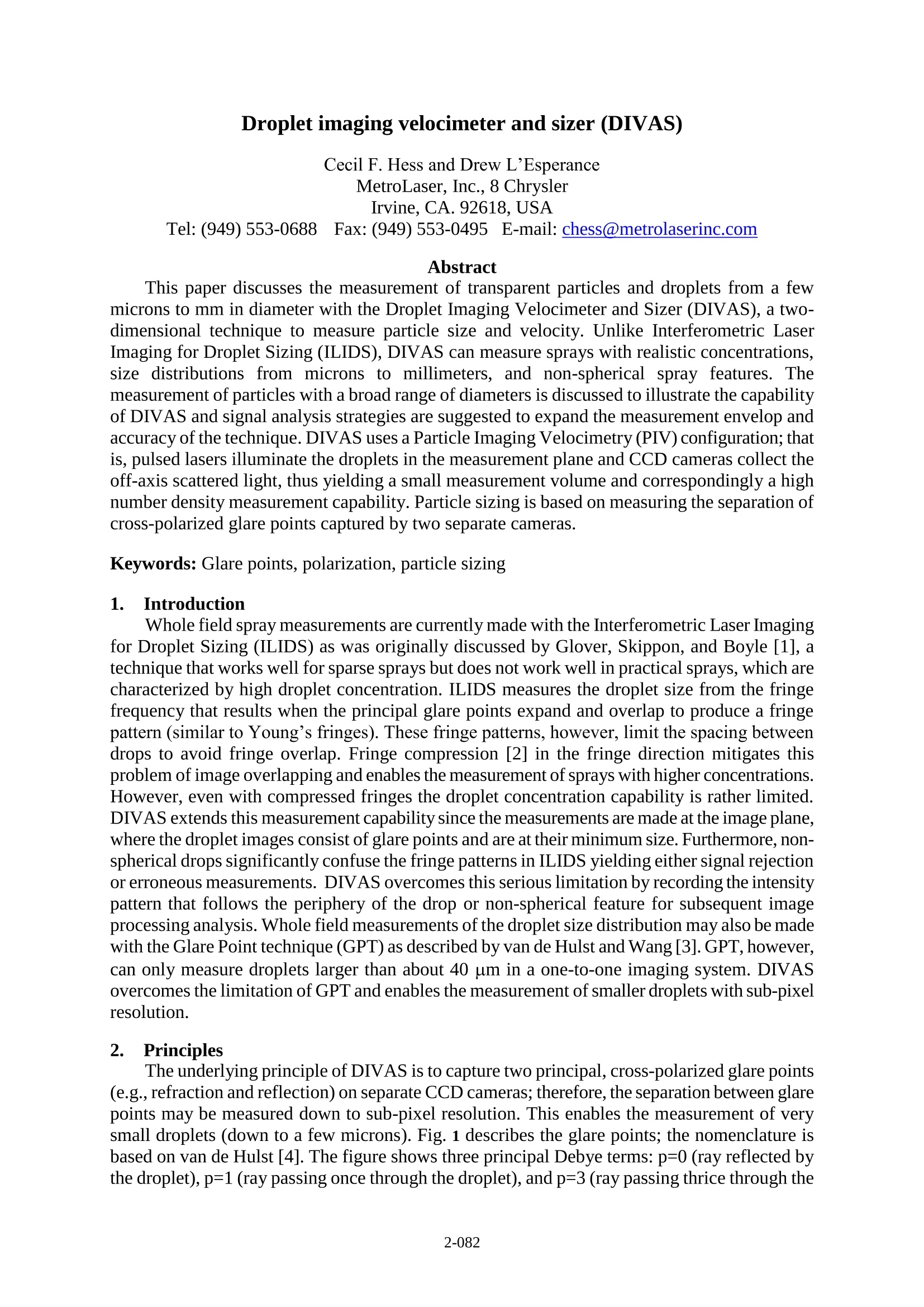
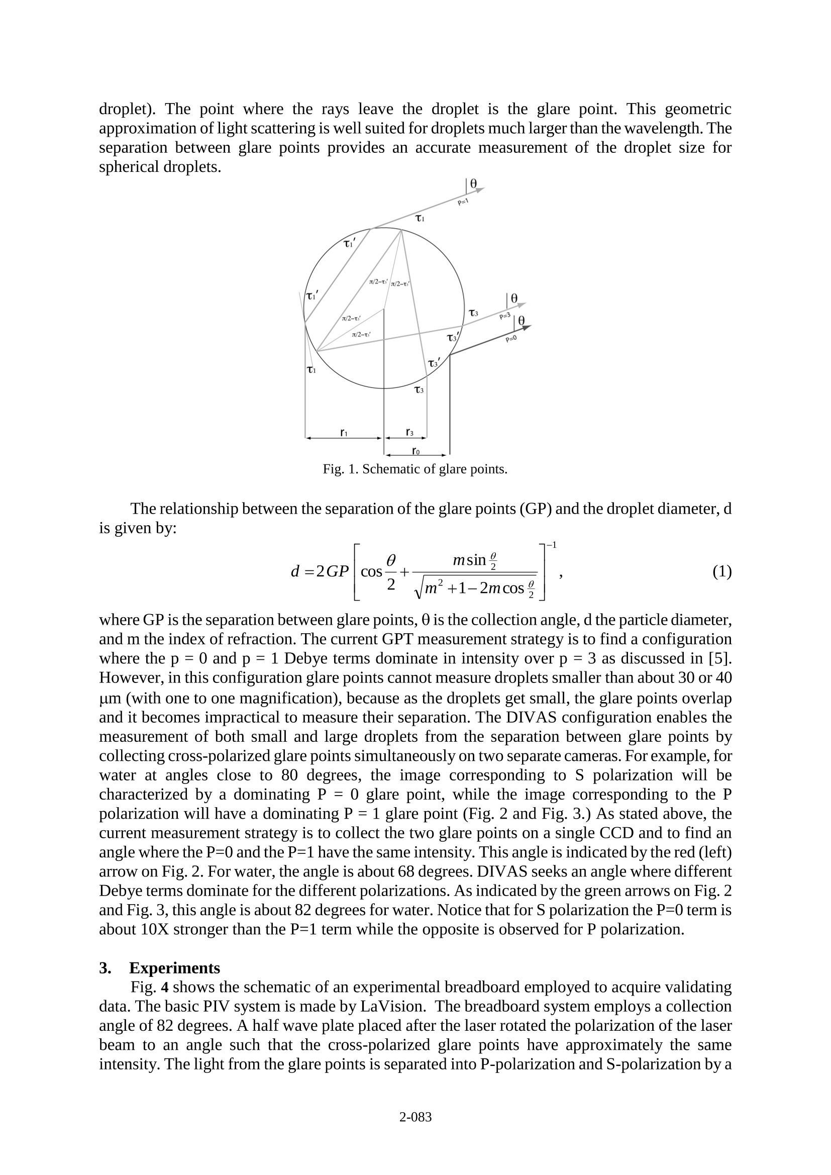
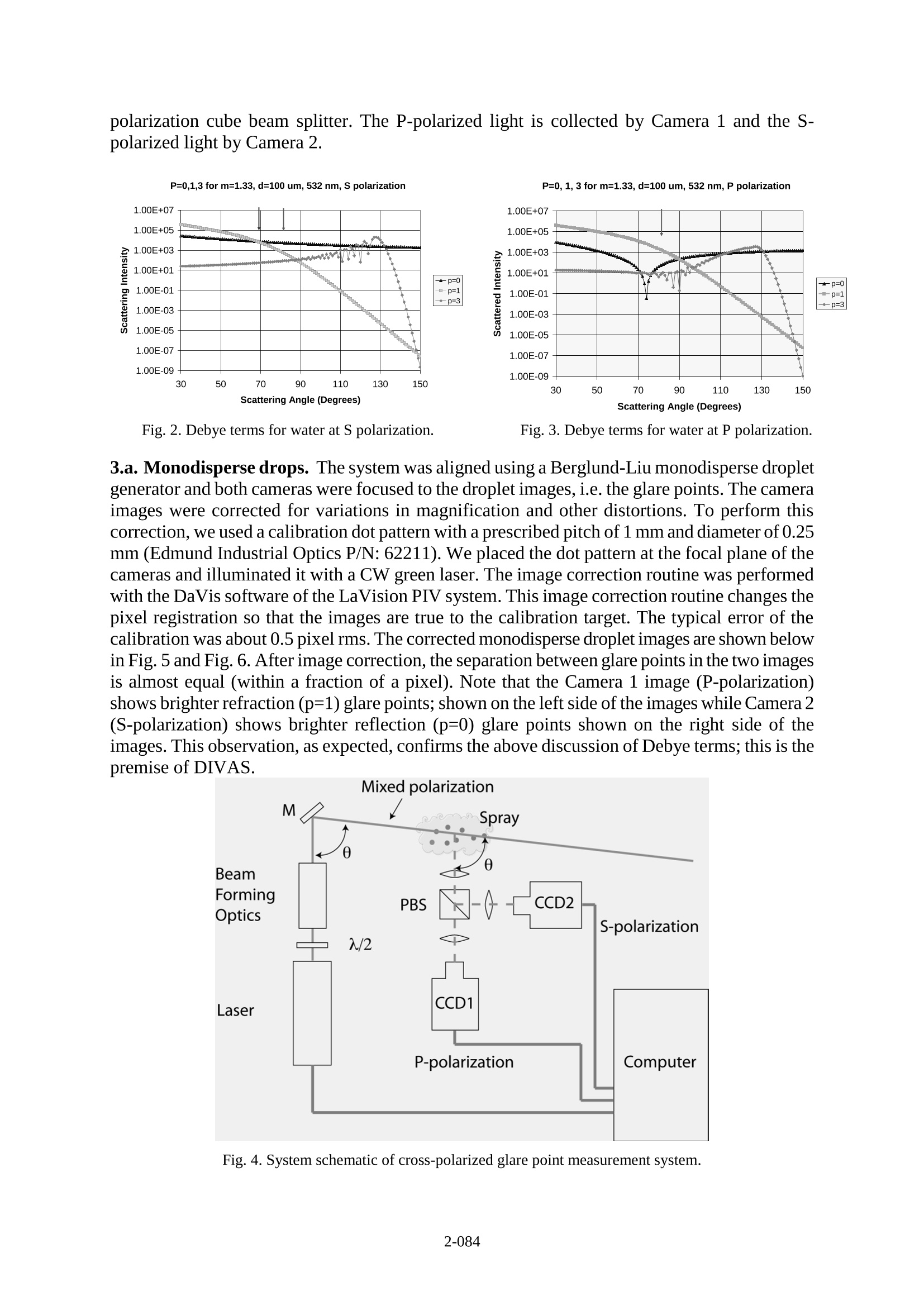
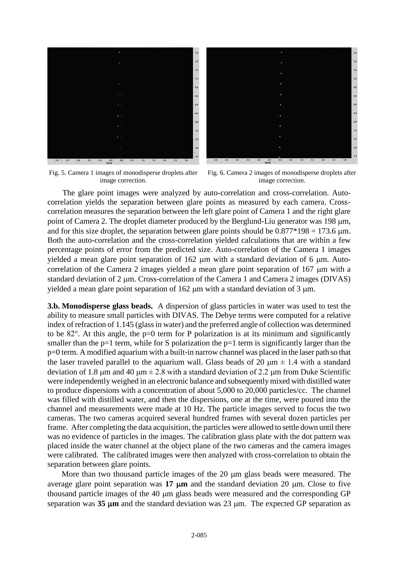
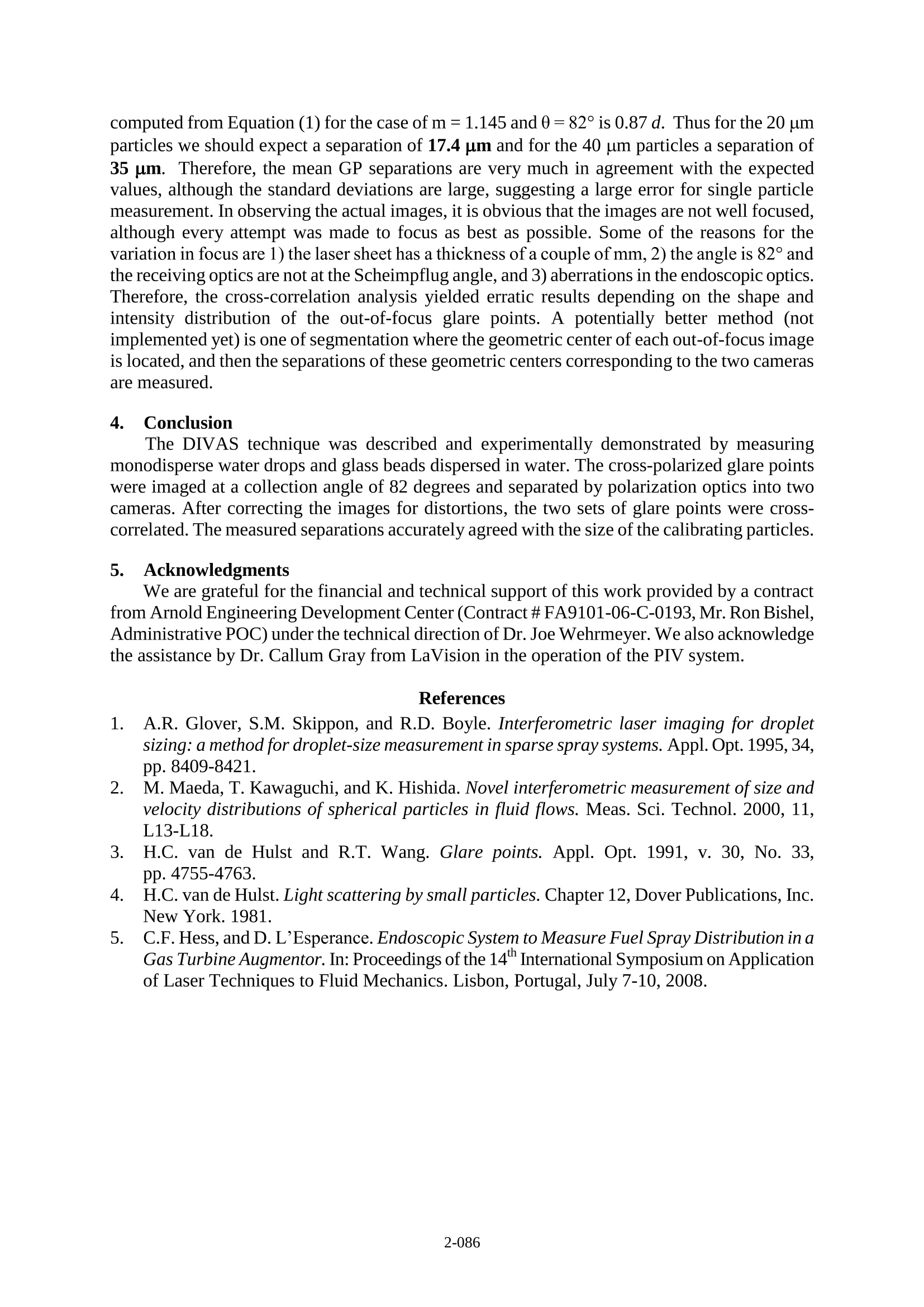
Droplet imaging velocimeter and sizer (DIVAS) Cecil F. Hess and Drew L'Esperance MetroLaser, Inc., 8 Chrysler Irvine, CA. 92618,USA Tel: (949) 553-0688Fax: (949)553-0495E-mail: chess@metrolaserinc.com .Abstract This paper discusses the measurement of transparent particles and droplets from a fewmicrons to mm in diameter with the Droplet Imaging Velocimeter and Sizer (DIVAS), a two-dimensional technique to measure particle size and velocity. Unlike Interferometric LaserImaging for Droplet Sizing (ILIDS), DIVAS can measure sprays with realistic concentrations,size distributions from microns to millimeters, and non-spherical spray features.Themeasurement of particles with a broad range of diameters is discussed to illustrate the capabilityof DIVAS and signal analysis strategies are suggested to expand the measurement envelop andaccuracy of the technique. DIVAS uses a Particle Imaging Velocimetry (PIV) configuration; thatis, pulsed lasers illuminate the droplets in the measurement plane and CCD cameras collect theoff-axis scattered light, thus yielding a small measurement volume and correspondingly a highnumber density measurement capability. Particle sizing is based on measuring the separation ofcross-polarized glare points captured by two separate cameras. Keywords: Glare points, polarization, particle sizing 1. Introduction Whole field spray measurements are currently made with the Interferometric Laser Imagingfor Droplet Sizing (ILIDS) as was originally discussed by Glover, Skippon, and Boyle [1], atechnique that works well for sparse sprays but does not work well in practical sprays, which arecharacterized by high droplet concentration. ILIDS measures the droplet size from the fringefrequency that results when the principal glare points expand and overlap to produce a fringepattern (similar to Young’s fringes). These fringe patterns, however, limit the spacing betweendrops to avoid fringe overlap. Fringe compression [2] in the fringe direction mitigates thisproblem of image overlapping and enables the measurement of sprays with higher concentrations.However, even with compressed fringes the droplet concentration capability is rather limited.DIVAS extends this measurement capability since the measurements are made at the image plane,where the droplet images consist of glare points and are at their minimum size. Furthermore, non-spherical drops significantly confuse the fringe patterns in ILIDS yielding either signal rejectionor erroneous measurements. DIVAS overcomes this serious limitation by recording the intensitypattern that follows the periphery of the drop or non-spherical feature for subsequent imageprocessing analysis. Whole field measurements of the droplet size distribution may also be madewith the Glare Point technique (GPT) as described by van de Hulst and Wang [3]. GPT, however,can only measure droplets larger than about 40 um in a one-to-one imaging system. DIVASovercomes the limitation of GPT and enables the measurement of smaller droplets with sub-pixelresolution. 2. Principles The underlying principle of DIVAS is to capture two principal, cross-polarized glare points(e.g.,refraction and reflection) on separate CCD cameras; therefore, the separation between glarepoints may be measured down to sub-pixel resolution. This enables the measurement of verysmall droplets (down to a few microns). Fig. 1 describes the glare points; the nomenclature isbased on van de Hulst [4].The figure shows three principal Debye terms: p=0 (ray reflected bythe droplet), p=1 (ray passing once through the droplet), and p=3 (ray passing thrice through the droplet). The point where the rays leave the droplet is the glare point. This geometricaapppjroximation of light scattering is well suited for droplets much larger than the wavelength. Theseparation between glare points provides an accurate measurement of the droplet size forspherical droplets. Fig. 1. Schematic of glare points. The relationship between the separation of the glare points (GP) and the droplet diameter, dis given by: where GP is the separation between glare points, 0 is the collection angle, d the particle diameter,and m the index of refraction. The current GPT measurement strategy is to find a configurationwhere the p=0 and p=1 Debye terms dominate in intensity over p=3 as discussed in [5].However, in this configuration glare points cannot measure droplets smaller than about 30 or 40um (with one to one magnification), because as the droplets get small, the glare points overlapand it becomes impractical to measure their separation. The DIVAS configuration enables themeasurement of both small and large droplets from the separation between glare points bycollecting cross-polarized glare points simultaneously on two separate cameras. For example, forwater at angles close to 80 degrees, the image corresponding to S polarization will becharacterized by a dominating P =0 glare point, while the image corresponding to the Ppolarization will have a dominating P =1 glare point (Fig. 2 and Fig. 3.) As stated above, thecurrent measurement strategy is to collect the two glare points on a single CCD and to find anangle where the P=0 and the P=1 have the same intensity. This angle is indicated by the red (left)arrow on Fig. 2. For water, the angle is about 68 degrees. DIVAS seeks an angle where differentDebye terms dominate for the different polarizations. As indicated by the green arrows on Fig. 2and Fig. 3, this angle is about 82 degrees for water. Notice that for S polarization the P=0 term isabout 10X stronger than the P=1 term while the opposite is observed for P polarization. 3. Experiments Fig. 4 shows the schematic of an experimental breadboard employed to acquire validatingdata. The basic PIV system is made by LaVision. The breadboard system employs a collectionangle of 82 degrees. A half wave plate placed after the laser rotated the polarization of the laserbeam to an angle such that the cross-polarized glare points have approximately the sameintensity. The light from the glare points is separated into P-polarization and S-polarization by a polarization cube beam splitter. The P-polarized light is collected by Camera 1 and the S-polarized light by Camera 2. Fig. 2. Debye terms for water at S polarization. Fig. 3. Debye terms for water at P polarization. 3.a.Monodisperse drops. The system was aligned using a Berglund-Liu monodisperse dropletgenerator and both cameras were focused to the droplet images, i.e. the glare points. The cameraimages were corrected for variations in magnification and other distortions. To perform thiscorrection, we used a calibration dot pattern with a prescribed pitch of 1 mm and diameter of 0.25mm (Edmund Industrial Optics P/N:62211). We placed the dot pattern at the focal plane of thecameras and illuminated it with a CW green laser. The image correction routine was performedwith the DaVis software of the LaVision PIV system. This image correction routine changes thepixel registration so that the images are true to the calibration target. The typical error of thecalibration was about 0.5 pixel rms. The corrected monodisperse droplet images are shown belowin Fig. 5 and Fig. 6. After image correction, the separation between glare points in the two imagesis almost equal (within a fraction of a pixel). Note that the Camera 1 image (P-polarization)shows brighter refraction (p=1) glare points; shown on the left side of the images while Camera 2(S-polarization) shows brighter reflection (p=0) glare points shown on the right side of theimages. This observation, as expected, confirms the above discussion of Debye terms; this is thepremise of DIVAS. Fig. 4. System schematic of cross-polarized glare point measurement system. Fig. 5. Camera 1 images of monodisperse droplets afterimage correction. Fig. 6. Camera 2 images of monodisperse droplets afterimage correction. The glare point images were analyzed by auto-correlation and cross-correlation. Auto-correlation yields the separa.....tion between glare points as measured by each camera. Cross-correlation measures the separation between the left glare point of Camera 1 and the right glarepoint of Camera 2. The droplet diameter produced by the Berglund-Liu generator was 198 um,and for this size droplet, the separation between glare points should be 0.877*198=173.6 um.Both the auto-correlation and the cross-correlation yielded calculations that are within a fewpercentage points of error from the predicted size. Auto-correlation of the Camera 1 imagesyielded a mean glare point separation of 162 um with a standard deviation of 6 um. Auto-correlation of the Camera 2 images yielded a mean glare point separation of 167 um with astandard deviation of 2 um. Cross-correlation of the Camera 1 and Camera 2 images (DIVAS)yielded a mean glare point separation of 162 um with a standard deviation of 3 um. 3.b. Monodisperse glass beads. A dispersion of glass particles in water was used to test theability to measure small particles with DIVAS. The Debye terms were computed for a relativeindex of refraction of 1.145 (glass in water) and the preferred angle of collection was determinedto be 82°. At this angle, the p=0 term for P polarization is at its minimum and significantlysmaller than the p=1 term, while for S polarization the p=1 term is significantly larger than thep=0 term. A modified aquarium with a built-in narrow channel was placed in the laser path so thatthe laser traveled parallel to the aquarium wall. Glass beads of 20 um ±1.4 with a standarddeviation of 1.8 um and 40 um ±2.8 with a standard deviation of 2.2 um from Duke Scientificwere independently weighed in an electronic balance and subsequently mixed with distilled waterto produce dispersions with a concentration of about 5,000 to 20,000 particles/cc. The channelwas filled with distilled water, and then the dispersions, one at the time, were poured into thechannel and measurements were made at 10 Hz. The particle images served to focus the twocameras. The two cameras acquired several hundred frames with several dozen particles perframe. Aftercompleting the data acquisition, the particles were allowed to settle down until therewas no evidence of particles in the images. The calibration glass plate with the dot pattern wasplaced inside the water channel at the object plane of the two cameras and the camera imageswere calibrated. The calibrated images were then analyzed with cross-correlation to obtain theseparation between glare points. More than two thousand particle images of the 20 um glass beads were measured. Theaverage glare point separation was 17 pm and the standard deviation 20 um. Close to fivethousand particle images of the 40 um glass beads were measured and the corresponding GPseparation was 35 pm and the standard deviation was 23 um. The expected GP separation as computed from Equation (1) for the case of m=1.145 and0=82° is 0.87 d. Thus for the 20 umparticles we should expect a separation of 17.4 pm and for the 40 um particles a separation of35 um. Therefore, the mean GP separations are very much in agreement with the expectedvalues, although the standard deviations are large, suggesting a large error for single particlemeasurement. In observing the actual images, it is obvious that the images are not well focused,although every attempt was made to focus as best as possible. Some of the reasons for thevariation in focus are 1) the laser sheet has a thickness of a couple of mm,2) the angle is 82° andthe receiving optics are not at the Scheimpflug angle, and 3) aberrations in the endoscopic optics.Therefore, the cross-correlation analysis yielded erratic results depending on the shape andintensity distribution of the out-of-focus glare points. A potentially better method (notimplemented yet) is one of segmentation where the geometric center of each out-of-focus imageis located, and then the separations of these geometric centers corresponding to the two camerasare measured. 4. Conclusion The DIVAS technique was described and experimentally demonstrated by measuringmonodisperse water drops and glass beads dispersed in water. The cross-polarized glare pointswere imaged at a collection angle of 82 degrees and separated by polarization optics into twocameras. After correcting the images for distortions, the two sets of glare points were cross-correlated. The measured separations accurately agreed with the size of the calibrating particles. 5. Acknowledgments We are grateful for the financial and technical support of this work provided by a contractfrom Arnold Engineering Development Center (Contract#FA9101-06-C-0193,Mr. Ron Bishel,Administrative POC) under the technical direction of Dr. Joe Wehrmeyer. We also acknowledgethe assistance by Dr. Callum Gray from LaVision in the operation of the PIV system. References 1. A.R. Glover, S.M. Skippon, and R.D. Boyle. Interferometric laser imaging for dropletsizing: a method for droplet-size measurement in sparse spray systems. Appl.Opt. 1995, 34,pp.8409-8421. ( 2. M. Maeda,T. Kawaguchi,and K. Hishida. Novel interferometric measurement ofsize andvelocity distributions of spherical particles in fluid flows. Meas. Sci. Technol. 2000, 11, L13-L18. ) ( 3. H.C. van de Hulst a nd R .T. W ang. G l are points. A ppl. Opt. 1991, v. 30, No. 33, pp. 4755-4763. ) 4. H.C. van de Hulst. Light scattering by small particles. Chapter 12, Dover Publications, Inc.New York. 1981. 5. C.F. Hess, and D. L'Esperance. Endoscopic System to Measure Fuel Spray Distribution in aGas Turbine Augmentor. In: Proceedings of the 14" International Symposium on Applicationof Laser Techniques to Fluid Mechanics. Lisbon, Portugal, July 7-10, 2008.
确定
还剩3页未读,是否继续阅读?

产品配置单

北京欧兰科技发展有限公司为您提供《液滴中粒径,速度检测方案(激光粒度仪)》,该方案主要用于其他中粒径,速度检测,参考标准--,《液滴中粒径,速度检测方案(激光粒度仪)》用到的仪器有LaVision ParticleMaster-Shadow 粒径测量系统、德国LaVision PIV/PLIF粒子成像测速场仪
推荐专场


相关方案
更多
该厂商其他方案
更多