


方案详情
文
The trajectory of the tip vortex of a reduced-scale, 1 m diameter, four-bladed rotor during hover
is studied using vortex methods combined with a center of mass analysis approach. The objective
is to develop analysis techniques capable of accurately characterizing the dynamical features of the
unsteady wake produced by rotorcraft during hover, descent, ascent and forward flight conditions.
Measurements of all three components of the velocity field are acquired using a stereo PIV system
synchronized to capture up to 260◦ wake age of the vortex with 10◦ offsets during hover conditions.
The nominal operating condition of the rotor is at a blade loading of CT / = 0.0645 and a rotational
speed of 1240RPM, corresponding to Rec = 180,000. An area encompassing the 95% confidence
region for the vortex jitter reveals a noticeable anisotropic, aperiodic pattern over all wake ages,
which has not been previously observed. The principal axis of the vortex jitter also appears to
align itself perpendicular to the slipstream boundary. An accurate characterization and prediction
of the trajectory of the individual tip vortices can significantly enhance the ability to design rotors
to meet specific performance targets such as reduction in fuselage vibrations, noise scattering and
maneuvering noise as well as an alleviation in the resuspension of particles during brownout
方案详情

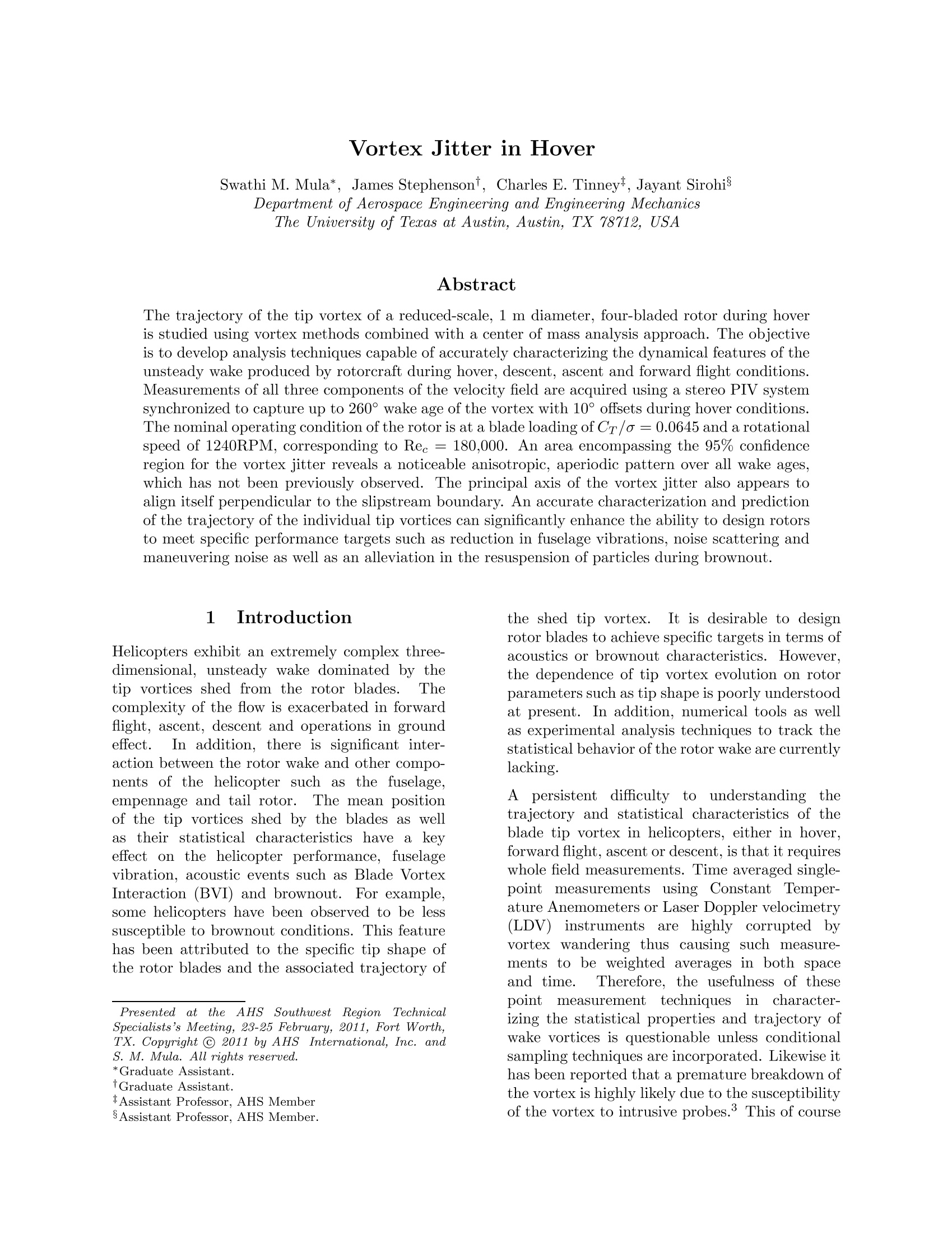
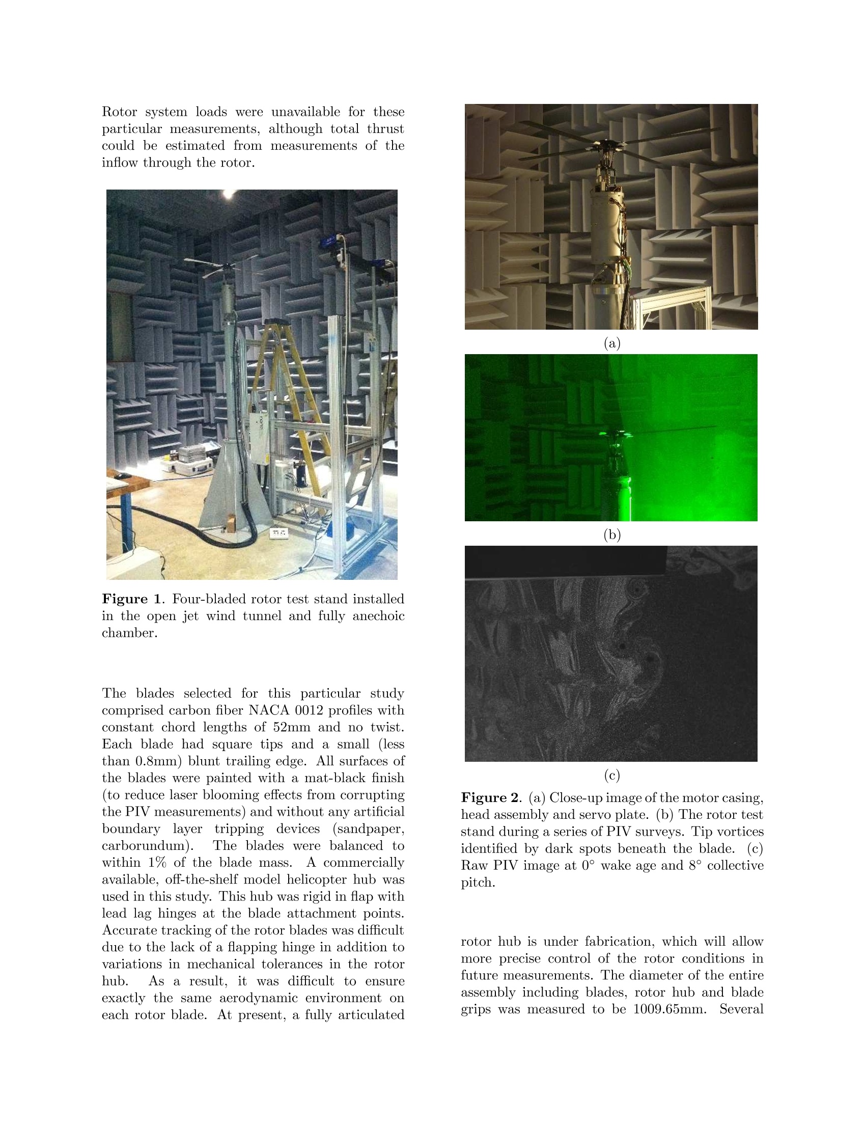
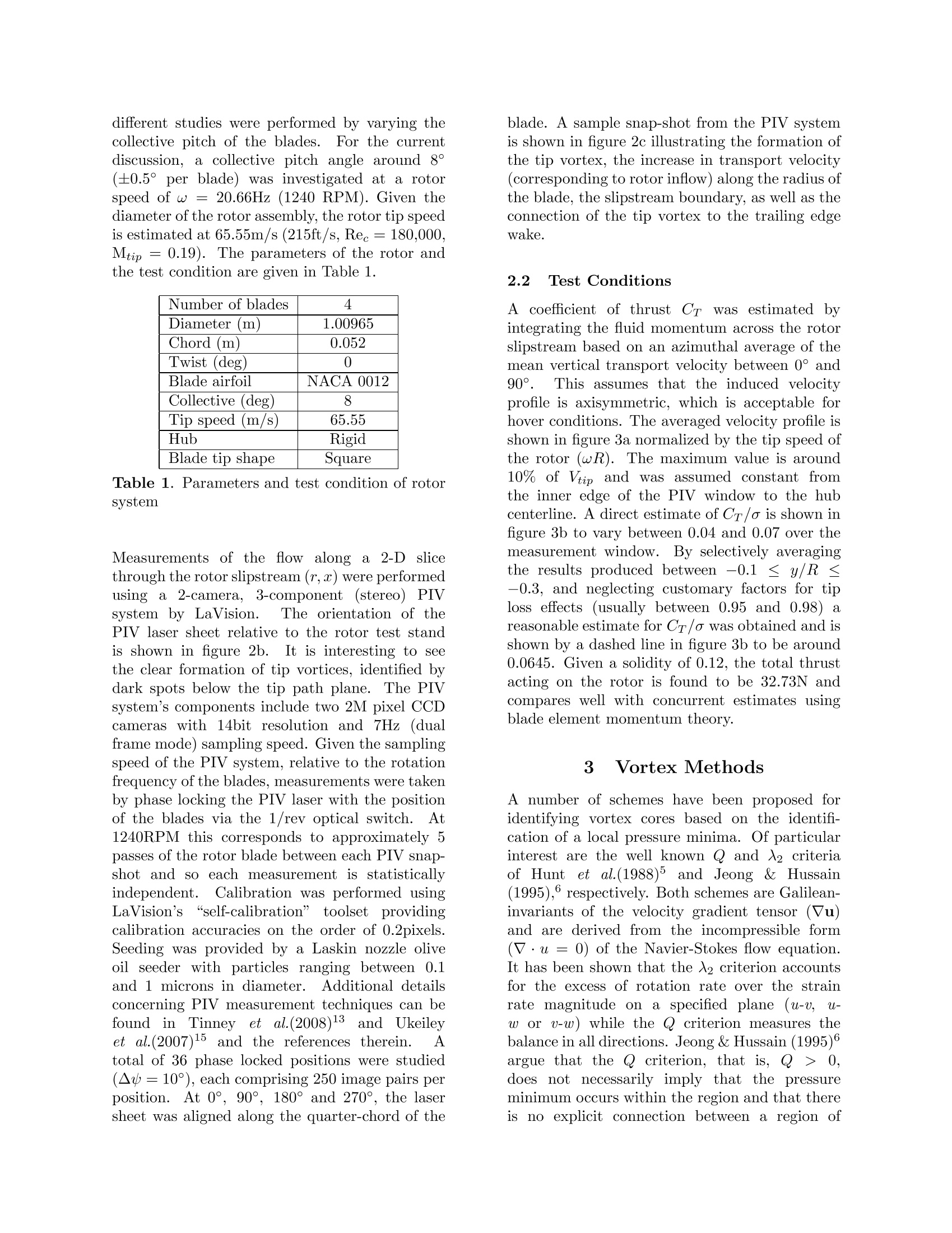
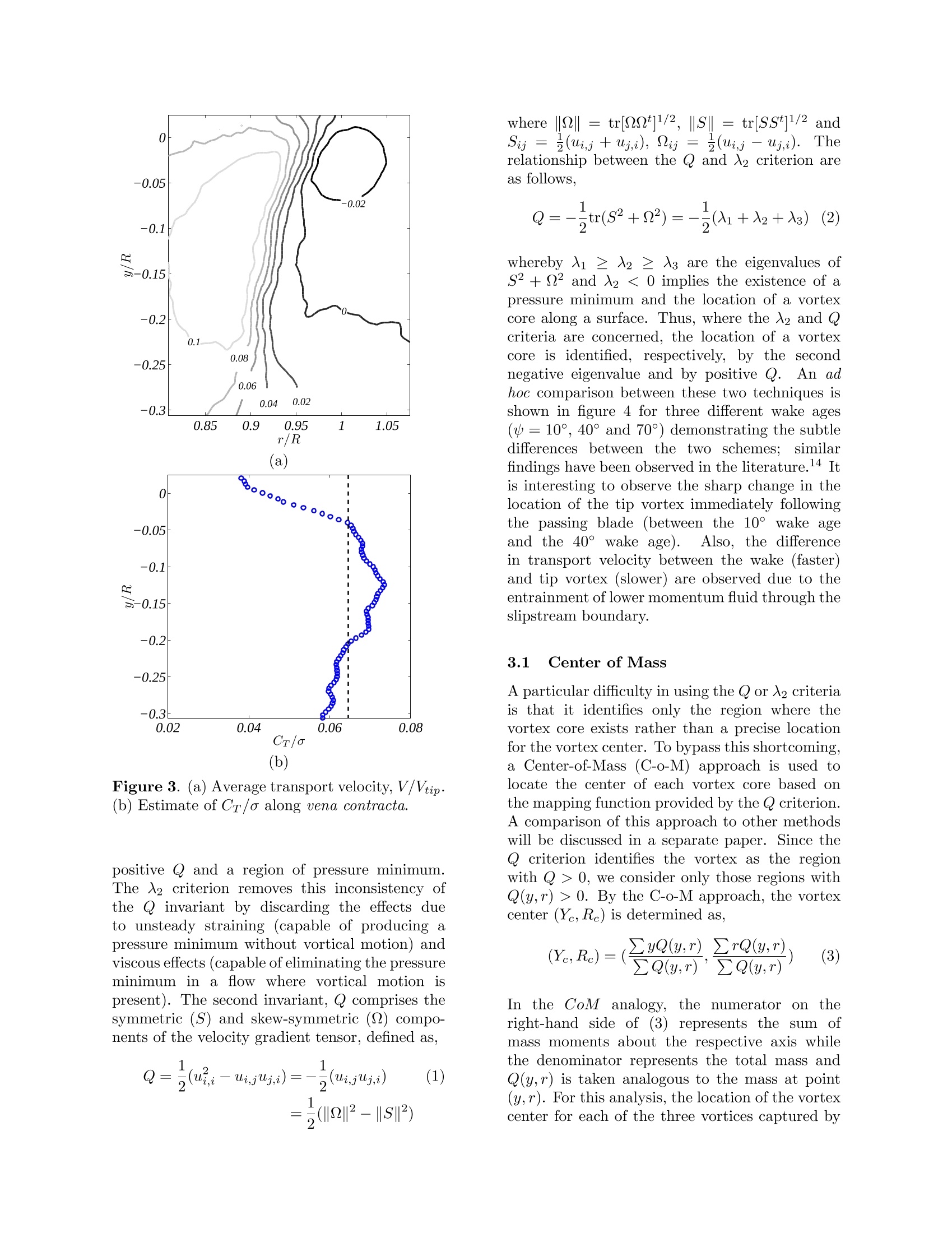
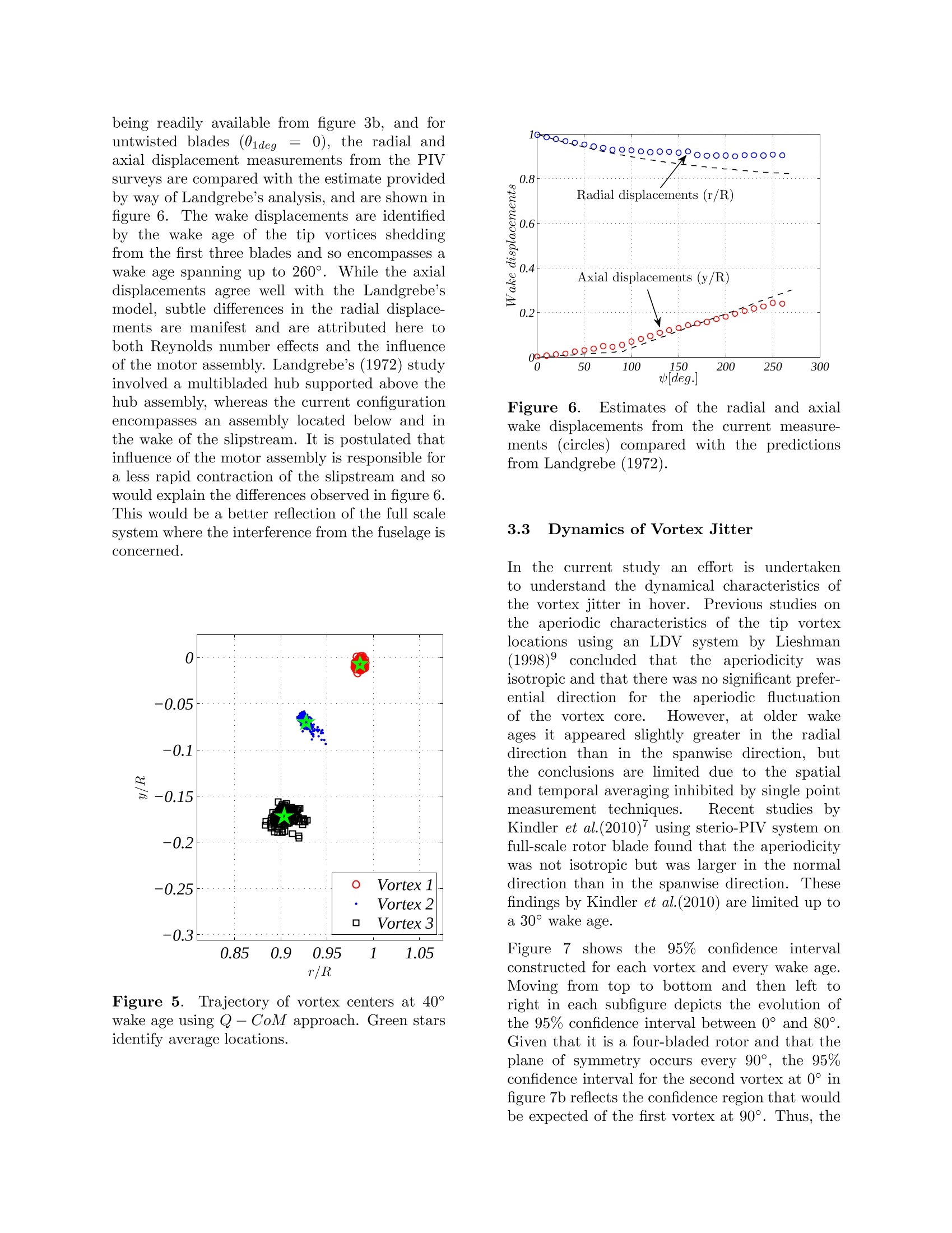
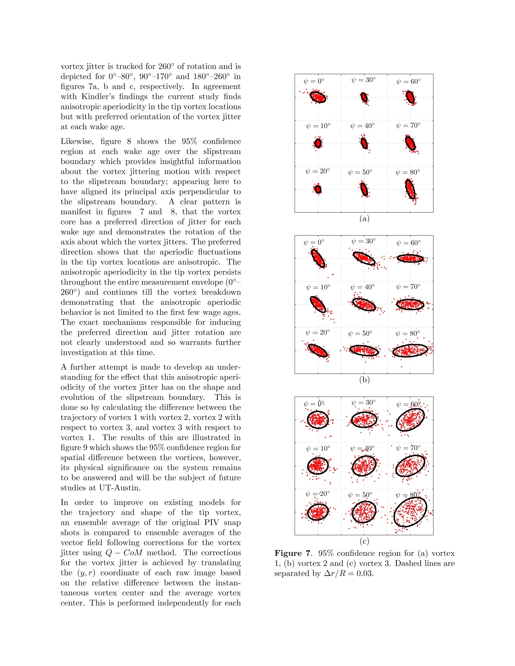
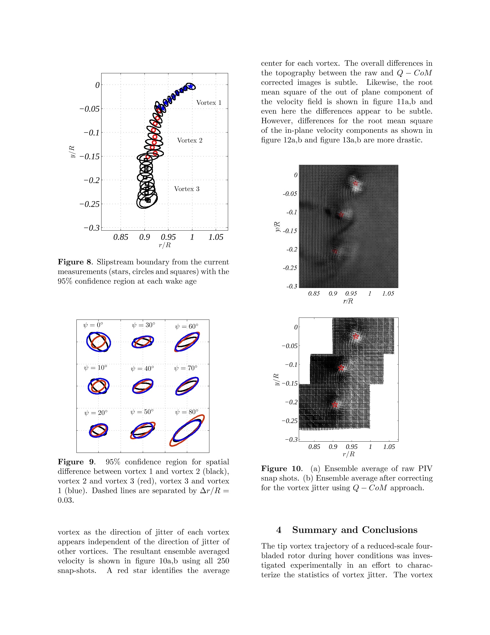
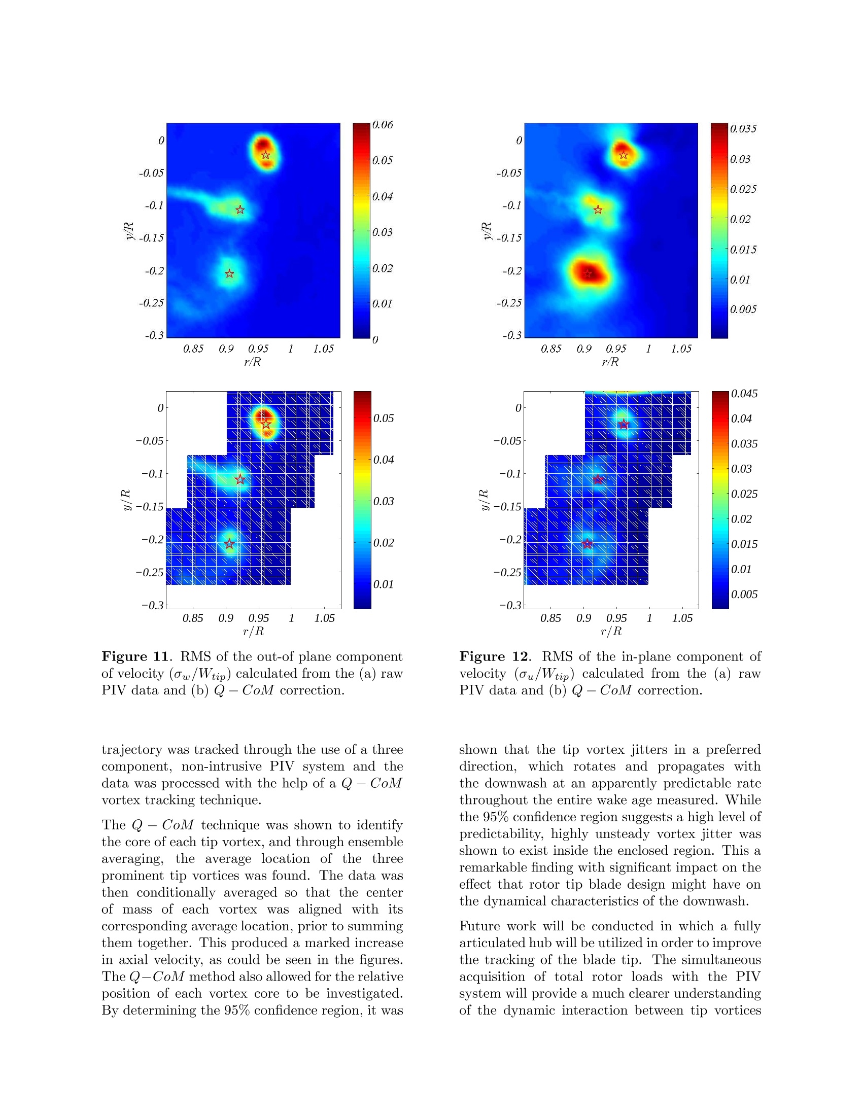
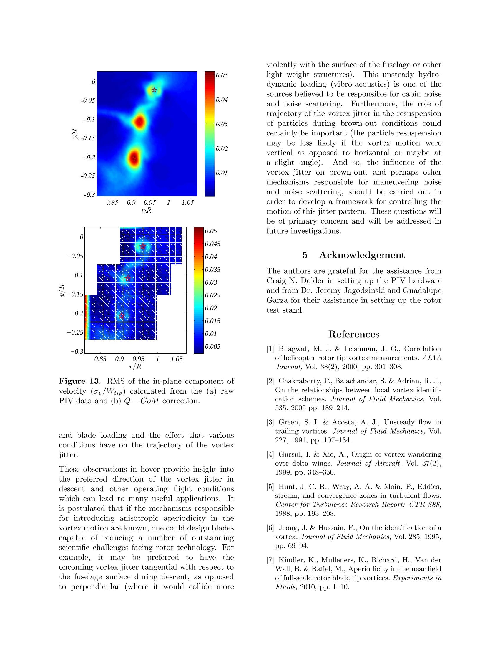
Vortex Jitter in Hover Swathi M. Mula*, James Stephensont, Charles E. Tinney, Jayant Sirohis Department of Aerospace Engineering and Engineering Mechanics The University of Texas at Austin, Austin, TX 78712, USA Abstract The trajectory of the tip vortex of a reduced-scale, 1 m diameter, four-bladed rotor during hoveris studied using vortex methods combined with a center of mass analysis approach. The objectiveis to develop analysis techniques capable of accurately characterizing the dynamical features of theunste wake produced by rotorcraft during hover, descent, ascent and forward flight conditions.Measurements of all three components of the velocity field are acquired using a stereo PIV systemsynchronized to capture up to 260° wake age of the vortex with 10°offsets during hover conditions.The nominal operating condition of the rotor is at a blade loading of Cr/a =0.0645 and a rotationalspeed of 1240RPM, corresponding to Ree =180,000. An area encompassing the 95% confidenceregion for the vortex jitter reveals a noticeable anisotropic, aperiodic pattern over all wake ages,which has not been previously observed. The principal axis of the vortex jitter also appears toalign itself perpendicular to the slipstream boundary. An accurate characterization and predictionof the trajectory of the individual tip vortices can significantly enhance the ability to design rotorsto meet specific performance targets such as reduction in fuselage vibrations, noise scattering andmaneuvering noise as well as an alleviation in the resuspension of particles during brownout. 1 Introduction Helicopters exhibit an extremely complex three-dimensional, unsteady wake dominated by thetip vortices shed from the rotor blades.Thecomplexity of the flow is exacerbated in forwardflight, ascent, descent and operations in groundeffect. In addition, there is significant inter-action between the rotor wake and other compo-nents of the lhelicopter such as the fuselage,empennage and tail rotor.The mean positionof the tip vortices shed by the blades as wellas their statistical characteristics have a keyeffect on the helicopter performance, fuselagevibration, acoustic events such as Blade VortexInteraction (BVI) and brownout.For example,some helicopters have been observed to be lesssusceptible to brownout conditions. This featurehas been attributed to the specific tip shape ofthe rotor blades and the associated trajectory of ( Presented at the AHS Southwest R egion Te chnicalSpec i alists’ s Meeting, 23-25 February, 2011, F ort W orth, TX. Copyright C 2011 by AHS International, Inc. and S. M. M ula. A l l rights reserued. ) ( *Graduate Assistant. ) ( TGraduate Assistant. ) ( A ssistant Professor , AHS Member ) ( Assistant Professor, AHS Member. ) the shed tip vortexX.. It is desirable to designrotor blades to achieve specific targets in terms ofacoustics or brownout characteristics. However.the dependence of tip vortex evolution on rotorparameters such as tip shape is poorly understoodat present. In addition, numerical tools as wellas experimental analysis techniques to track thestatistical behavior of the rotor wake are currentlylacking. A persistentdifficulty too understandingthetrajectory and statistical characteristics of theblade tip vortex in helicopters, either in hover,forward flight, ascent or descent, is that it requireswhole field measurements. Time averaged single-point measurements uusing ConstantTemper-ature Anemometers or Laser Doppler velocimetry(LDV))instrumentsare hhighly corrupted byvortex wandering thus causing such measure-ments to be weighted averages in both spaceand time. Therefore, the usefulness of thesepointtmeasurementttechniquesin. character-izing the statistical properties and trajectory ofwake vortices is questionable unless conditionalsampling techniques are incorporated. Likewise ithas been reported that a premature breakdown ofthe vortex is highly likely due to the susceptibilityof the vortex to intrusive probes. This of course limits reliable measurement techniques to laserbased systems (LDV), which posses restrictionsof their own, given the random arrival of particlesthrough the measurement volume and the correc-tions that must be applied thereafter. Whilenumerous studies have been conducted on aperi-odicity, vortex wandering and turbulence charac-1.3.4teristics of vortices using point techniques (1,3,4,9)they fail to accurately capture the true dynamicalcharacteristics of the tip vortex, especially in thefar-field (wake ages beyond a few chord lengthsfrom the blade) where wandering is excessive.This is certainly no fault of the experimen-talist, and so has prompted demands for spatiallyresolved measurement techniques, which havebecome more sophisticated over the past decadewith the advent of commercially available digitalParticle Image Velocimetry (PIV) systems. An oftenforgotten featureof PIV (evenTomographic -PIV) is its unique ability to capturevorticity,thus makingitt aaperfectly suitedinstrument for accurately characterizing the wakeand slipstream generated by rotors. In the currentstudy, the trajectory and statistical character-istics of the tip vortex of a four-bladed rotorduring hover is analyzed by means of vortexmethods and a Center-of-Mass approach.Thisis done in an effort to identify the mecha-nisms responsible for vortex wander observedpreviously by others. In the classical sense,“vortex wandering” is defined as the randomdisplacement of the vortex core and is believedto be driven by an interaction with the Kelvin-Hemholtz instability of the shear layer.4 Similarefforts have been explored elsewhere includinga comparison of various aperiodicity correctiontechniques(centroid of vorticity,, peakaxialvelocity, helicity, vortex methods, swirl center) byRamasamy et al.(2009).10 However, in the currentstudy, corrections for vortex jitter are used tocharacterize the dynamical lifecycle of the vorticesover extended wake ages. These new findingsprovide insight into the mechanism(s) responsiblefor some of the outstanding scientific challengesfacing current and next generation vertical lifttechnology. 2 Experimental Arrangement 2.1 Facility and Instrumentation The current studywas conducted inaanewexperimental ffluid dynamics facilityy atTheUniversity of Texasat Austin'sJ.J. Pickle Research Campus (UT-PRC). A more detailedoverview of thislsfacility canbefoundathttp://www.ae.utexas.edu/facultysites/tinney/and is one of three new test facilities that havebeen constructed recently at UT-Austin to studyproblemslin rotorcprcraft. An overview of theother new facilities are described in Sicard &Sirohi(2010)11 and Stephenson eet al.(2010).12Highlights of this experimental fluid dynamicsfacility include an 18ft. x 20ft. x 24ft. (exteriordimension) fully anechoic chamber integratedwitht a subsonic open circuit, open-jet windtunnel. Interior dimensions of the chamber(wedge tip to wedge tip) are 12ft.×14ft.×18ft.whilee all surfaces (walls, fflloooorr aand ceiling),are treated with wedges designed for a soundabsorption coefficient greater than 99% above100Hz.u.An 84inch diameter, 500HP van axialfan capable of providing 244,000CFM locateddownstream of the collector allows a centerlinevelocity of 330ft/s (Mach 0.3) to be achievedthrough a variable geometry open-jet test section(Mach 0.3 through a 3ftx4ft. and Mach <0.22through a 4ftx4ft. test section). For the presentstudy, only hover conditions were of interestand so the wind tunnel was not used. Likewise.no sound measurements were conducted and sothe floor wedges were removed (hemi-anechoicchamber) in order to provide easy adjustment ofoptical instruments. Acustom fabricatedreduced-scale rotor teststandprovided theienecessary conditionsSforcharacterizing the vortex trajectory from a four-bladed rotor at various wake ages and collectivepitch angles. Installation of this rotor test standin the center of the anechoic chamber is shown infigure 1 followed by a close-up view of the upperassembly in figure 2a. At the heart of this teststand is a 9kW electric motor powered by a 10kW(max) Lambda TKE ESS 50-200 programmableDC power supply that outputs up to 50V at 200A.The motor is capable of a maximum rotationalspeed of 8000RPMI((133Hz)and a maximumtorque of 10Nm.A custom fabricated opticalencoder fixed to the motor allows both 1/rev and60/rev positioning of the rotor to be phase alignedwith other laboratory instruments (PIV, DIC,acoustics, etc).).This is especially important fordeveloping accurate statistical models of the wakeage and far-field/ near-field acoustic signaturesas a function of rotor azimuth. For the currentstudy, a four-bladed hub assembly was mountedon the rotor shaft. The rotor was driven directlyby the electric motor, without a transmission. Rotor system loads were unavailable for theseparticular measurements, although total thrustcould be estimated from measurements of theinflow through the rotor. Figure 1. Four-bladed rotor test stand installedin the open jet wind tunnel and fully anechoicchamber. The blades selected for thisSparticular studycomprised carbon fiber NACA 0012 profiles withconstant chord lengths of 52mm and no twist.Each blade had square tips and a small (lessthan 0.8mm) blunt trailing edge. All surfaces ofthe blades were painted with a mat-black finish(to reduce laser blooming effects from corruptingthe PIV measurements) and without any artificialboundary layertripping devices(sandpaper,carborundum).The bladesine were balanced towithin 1% of the blade mass.A commerciallyavailable, off-the-shelf model helicopter hub wasused in this study. This hub was rigid in flap withlead lag hinges at the blade attachment points.Accurate tracking of the rotor blades was difficultdue to the lack of a flapping hinge in addition tovariations in mechanical tolerances in the rotorhub. As a result, it was difficult to ensureexactly the same aerodynamic environment oneach rotor blade. At present, a fully articulated (a) (b) (c) Figure 2. (a) Close-up image of the motor casing,head assembly and servo plate. (b) The rotor teststand during a series of PIV surveys. Tip vorticesidentified by dark spots beneath the blade. (c)Raw PIV image at 0°wake age and 8°collectivepitch. rotor hub is under fabrication, which will allowmore precise control of the rotor conditions infuture measurements. The diameter of the entireassembly including blades, rotor hub and bladegrips was measured to be 1009.65mm.Several different studies were performed by varying thecollective pitch of the blades..For the currentdiscussion, a collective pitch angle around 8°(±0.5°1per blade)) was investigated at a rotorspeed of w =20.66Hz (1240 RPM). Given thediameter of the rotor assembly, the rotor tip speedis estimated at 65.55m/s (215ft/s, Rec=180,000,Mtip=0.19). The parameters of the rotor andthe test condition are given in Table 1. Number of blades 4 Diameter (m) 1.00965 Chord (m) 0.052 Twist (deg) 0 Blade airfoil NACA 0012 Collective (deg) 8 Tip speed (m/s) 65.55 Hub Rigid Blade tip shape Square Table 1. Parameters and test condition of rotorsystem Measurements of the flow along a 2-D slicethrough the rotor slipstream (r, c) were performedusing a 2-camera,3-component((stereo) PIVsystem by LaVision. The orientation of thePIV laser sheet relative to the rotor test standis shown in figure 2b.It is interesting to seethe clear formation of tip vortices, identified bydark spots below the tip path plane.The PIVsystem’s components include two 2M pixel CCDcameraswith 14bit resolution and 7Hz (dualframe mode) sampling speed. Given the samplingspeed of the PIV system, relative to the rotationfrequency of the blades, measurements were takenby phase locking the PIV laser with the positionof the blades via the 1/rev optical switch. At1240RPM this corresponds to approximately 5passes of the rotor blade between each PIV snap-shot and so each measurement is statisticallyindependent. Calibration was performed usingLaVision's L“Lself-calibration” toolsett providingcalibration accuracies on the order of 0.2pixels.Seeding was provided by a Laskin nozzle oliveoilseeder with1Tparticles ranging between 0.1and 1 microns in diameter.Additional detailsconcerning PIV measurement techniques can befound in Tinney et al.(2008)13and Ukeileyet al.(2007)15 and the references therein. Atotal of 36 phase locked positions were studied(Aw=10°), each comprising 250 image pairs perpn21osition. At 0°, 90°,180°and270°, the lasersheet was aligned along the quarter-chord of the blade. A sample snap-shot from the PIV systemis shown in figure 2c illustrating the formation ofthe tip vortex, the increase in transport velocity(corresponding to rotor inflow) along the radius ofthe blade, the slipstream boundary, as well as theconnection of the tip vortex to the trailing edgewake. 2.2 Test Conditions A coefficient of thrust Crwas estimated byintegrating the fluid momentum across the rotorslipstream based on an azimuthal average of themean vertical transport velocity between 0° and90°..This assumes that the induced velocityprofile is axisymmetric, which is acceptable forhover conditions. The averaged velocity profile isshown in figure 3a normalized by the tip speed ofthe rotor (wR).. The maximum value is around10% of Vtip and was88assumed constant fromthe inner edge of the PIV window to the hubcenterline. A direct estimate of Cr/o is shown infigure 3b to vary between 0.04 and 0.07 over themeasurement window. By selectively averagingthe results produced between -0.1 ≤y/R <-0.3, and neglecting customary factors for tiploss effects (usually between 0.95 and 0.98) areasonable estimate for Cr/o was obtained and isshown by a dashed line in figure 3b to be around0.0645. Given a solidity of 0.12, the total thrustacting on the rotor is found to be 32.73N andcompares well with concurrent estimates usingblade element momentum theory. 3 Vortex Methods A number of schemes have been proposed foridentifying vortex cores based on the identifi-cation of a local pressure minima. Of particularinterest are the well known Q and 2 criteriaof Hunt et al.(1988)5and Jeong & Hussain(1995),6 respectively. Both schemes are Galilean-invariants of the velocity gradient tensor (Vu)and are derived from the incompressible form(V·u=0) of the Navier-Stokes flow equation.It has been shown that the 一2 criterion accountsfor the excess of rotation rate over the strainrate magnitude on a specified plane (u-u, uu-w or u-w) while the Q criterion measures thebalance in all directions. Jeong & Hussain (1995)6argue that the Q criterion, that is, Q> 0,does not necessarily imply that the pressureminimum occurs within the region and that thereis no explicit connection between a region of Figure 3. (a) Average transport velocity, V/Vtip·(b) Estimate of Cr/o along vena contracta. positive Q and a region of pressure minimum.The A2 criterion removes this inconsistency ofthe Q invariant by discarding the effects dueto unsteady straining (capable of producing apressure minimum without vortical motion)andviscous effects (capable of eliminating the pressureminimum in a flow where vortical motion ispresent). The second invariant, Q comprises thesymmetric (S) and skew-symmetric (Q) compo-nents of the velocity gradient tensor,defined as, where||Q||=tr[22*]1/2, IS||= tr[SS*]1/2 andSij=(ui,j+uj,i), Qij =(ui,j-uj,i).Therelationship between the Q and 入2 criterion areas follows. whereby 入1 ≥2 A3 are the eigenvalues ofS+and A2 <0 implies the existence of apressure minimum and the location of a vortexcore along a surface. Thus, where the 2 and Qcriteria are concerned, the location of a vortexcore is identified, respectively, by the secondnegative eigenvalue and by positive Q. An adhoc comparison between these two techniques isshown in figure 4 for three different wake ages(y=10°, 40° and 70°) demonstrating the subtledifferences between the two schemes:;similarfindings have been observed in the literature.14 Itis interesting to observe the sharp change in thelocation of the tip vortex immediately followingthe passing blade (between the 10° wake ageand the 40° wake age). Also, the differencein transport velocity between the wake (faster)and tip vortex (slower) are observed due to theentrainment of lower momentum fluid through theslipstream boundary. 3.1 Center of Mass A particular difficulty in using the Q or 2 criteriais that it identifies only the region where thevortex core exists rather than a precise locationfor the vortex center. To bypass this shortcoming,a Center-of-Mass (C-o-M) approach is used tolocate the center of each vortex core based onthe mapping function provided by the Q criterion.A comparison of this approach to other methodswill be discussed in a separate paper. Since theQ criterion identifies the vortex as the regionwith Q>0, we consider only those regions withQ(y,r)> 0. By the C-o-M approach, the vortexcenter (Yc,R) is determined as, In the CoM analogy, the numerator on theright-hand side of (3) represents the sum ofmass moments about the respective axis whilethe denominator represents the total mass andQ(y,r) is taken analogous to the mass at point(y,r). For this analysis, the location of the vortexcenter for each of the three vortices captured by 0 -0.05 -0.3 0.85 0.9 0.95 1.05 r/R Figure 4.. Vortex Methods (X2-green and Q-white) applied to sample PIV vector maps at 10°,40°,and 70°wake age (top to bottom). the PIV system are analyzed separately.Theamount of jitter that each vortex undergoes istracked and shown in figure 5 from the conditioncorresponding to = 40°wake age. Agreenstar identifies the average location of the vortexbased on the 250 PIV snap-shots. It can be seenfrom this illustration how the amount of jitterincreases with vortex age due to a steady growthof instabilities along the slipstream boundary.Close inspection reveals the third vortex encom-passing nearly three times the region of space asthe first tip vortex. This is not to be confusedwith vorticity diffusion, which also increases withwake age due to competing effects of angularmomentum with viscous diffusion and turbulencegeneration. Although,,it is postulated thatvorticity diffusion and vortex jitter are coupledphenomena. 3.2 Slipstream Boundary With the vortex center known, the slipstreamboundary is determined and compared with theempirical trends of Landgrebe (1972).8 Based ona systematic series of measurements of a rotor inhover, Landgrebe (1972) showed that the axialand radial coordinate of the tip vortex couldbe estimated using the following approximaterelations: where b is the number of blades, the constant kis the vertical transport velocity of the tip vortexdivided by the rotor tip speed and can be uniquelydetermined by Cr/o as, while the constant k2 is the tangent of the localpitch angle of the contracted helix (中w) of the tipvortex in the stable near wake region describedby, Likewise, the radial coordinates could be deter-mined by substituting A=0.78 and=0.145+27Cr into equation (5). With the blade loading being readily available from figure 3b, and foruntwisted blades (01deg=0), the radial andaxial displacement measurements from the PIVsurveys are compared with the estimate providedby way of Landgrebe’s analysis, and are shown infigure 6. The wake displacements are identifiedby the wake age of the tip vortices sheddingfrom the first three blades and so encompasses awake age spanning up to 260°. While the axialdisplacements agree well with the Landgrebe’smodel, subtle differences in the radial displace-ments are manifest and are attributed here toboth Reynolds number effects and the influenceof the motor assembly. Landgrebe’s (1972) studyinvolved a multibladed hub supported above thehub assembly, whereas the current configurationencompasses an assembly located below and inthe wake of the slipstream. It is postulated thatinfluence of the motor assembly is responsible fora less rapid contraction of the slipstream and sowould explain the differences observed in figure 6.This would be a better reflection of the full scalesystem where the interference from the fuselage isconcerned. Figure 5. Trajectory of vortex centers at 40°wake age using Q-CoM approach. Green starsidentify average locations. Figure 6. Estimates of the radial and axialwake displacements from the current measure-ments (circles) compared with the predictionsfrom Landgrebe (1972). 3.3 Dynamics of Vortex Jitter In the current study an effort is undertakento understand the dynamical characteristics ofthe vortex jitter in hover. Previous studies onthe aperiodic characteristics of the tip vortexlocations using an LDV system by Lieshman(1998) concluded that the aperiodicity wasisotropic and that there was no significant prefer-ential direction for the aperiodic fluctuationof the vortex core. However, at older wakeages it appeared slightly greater in the radialdirection than in the spanwise direction, butthe conclusions are limited due to the spatialand temporal averaging inhibited by single pointmeasurement techniques. Recent studies byKindler et al.(2010)7 using sterio-PIV system onfull-scale rotor blade found that the aperiodicitywas not isotropic but was larger in the normaldirection than in the spanwise direction. Thesefindings by Kindler et al.(2010) are limited up toa 30° wake age. Figure 7 shows t confidence intervalconstructed for each vortex and every wake age.Moving from top to bottom and then left toright in each subfigure depicts the evolution ofthe 95% confidence interval between 0°and 80°.Given that it is a four-bladed rotor and that theplane of symmetry occurs every 90°, the 95%confidence interval for the second vortex at 0° infigure 7b reflects the confidence region that wouldbe expected of the first vortex at 90°. Thus, the vortex jitter is tracked for 260°of rotation and isdepicted for 0°-80°,90°-170° and 180°-260° infigures 7a, b and c, respectively. In agreementwith Kindler’s findings the current study findsanisotropic aperiodicity in the tip vortex locationsbut with preferred orientation of the vortex jitterat each wake age. Likewise.figure 8 shows the 95%confidenceregion at each wake age over the slipstreamboundary which provides insightful informationabout the vortex jittering motion with respectto the slipstream boundary; appearing here tohave aligned its principal axis perpendicular tothe slipstream boundary. A clear pattern ismanifest in figures 7 and88, that the vortexcore has a preferred direction of jitter for eachwake age and demonstrates the rotation of theaxis about which the vortex jitters. The preferreddirection shows that the aperiodic fluctuationsin the tip vortex locations are anisotropic. Theanisotropic aperiodicity in the tip vortex persiststhroughout the entire measurement envelope(0°-260°) and continues till the vortex breakdowndemonstrating tthatthe anisotropic aperiodicbehavior is not limited to the first few wage ages.The exact mechanisms responsible for inducingthe preferred direction and jitter rotation arenot clearly understood and so warrants furtherinvestigation at this time. A further attempt is made to develop an under-standing for the effect that this anisotropic aperi-odicity of the vortex jitter has on the shape andevolution of the slipstream boundary. This isdone so by calculating the difference between thetrajectory of vortex 1 with vortex 2, vortex 2 withrespect to vortex 3, and vortex 3 with respect tovortex 1. The results of this are illustrated infigure 9 which shows the 95% confidence region forspatial difference between the vortices, however,its physical significance on the system remainsto be answered and will be the subject of futurestudies at UT-Austin. In order to improvee on existingmodelsforthe trajectory and shape of the tipvortex.an ensemble average of the original PIV snapshots is compared to ensemble averages of thevector field following corrections for the vortexjitter using Q- CoM method. The correctionsfor the vortex jitter is achieved by translatingthe (y,r) coordinate of each raw image basedon the relative difference between the instan-taneous vortex center and the average vortexcenter. This is performed independently for each =0° =:30° 山=60° =1 山=:40° 山=70° w=20° 山==50° w=808 (c) Figure 7. 95% confidence region for (a) vortex1, (b) vortex 2 and (c) vortex 3. Dashed lines areseparated by ▲r/R=0.03. Figure 8. Slipstream boundary from the currentmeasurements (stars, circles and squares) with the95% confidence region at each wake age Figure 9. 95% confidence region for spatialdifference between vortex 1 and vortex 2 (black),vortex 2 and vortex 3 (red), vortex 3 and vortex1 (blue). Dashed lines are separated by ▲r/R=0.03. vortex as the direction of jitter of each vortexappears independent of the direction of jitter ofother vortices. The resultant ensemble averagedvelocity is shown in figure 10a,b using all 250snap-shots.5. A red star identifies the average center for each vortex. The overall differences inthe topography between the raw and Q- CoMcorrected images is subtle. Likewise,the rootmean square of the out of plane component ofthe velocity field is shown in figure 11a,b andeven here the differences appear to be subtle.However, differences for the root mean squareof the in-plane velocity components as shown infigure 12a,b and figure 13a,b are more drastic. Figure 10. (a) Ensemble average of raw PIVsnap shots. (b) Ensemble average after correctingfor the vortex jitter using Q-CoM approach. 4 Summary and Conclusions The tip vortex trajectory of a reduced-scale four-bladed rotor during hover conditions was inves-tigated experimentally in an effort to charac-terize the statistics of vortex jitter. The vortex r/R Figure 11. RMS of the out-of plane componentof velocity (ow/Wtip) calculated from the (a) rawPIV data and (b)Q-CoM correction.1. trajectory was tracked through the use of a threecomponent, non-intrusive PIV system and thedata was processed with the help of a Q- CoMvortex tracking technique. The Q- CoM technique was shown to identifythe core of each tip vortex, and through ensembleaveraging,,the average location of the threeprominent tip vortices was found. The data wasthen conditionally averaged so that the centerof mass of each vortex was aligned with itscorresponding average location, prior to summingthem together. This produced a marked increasein axial velocity, as could be seen in the figures.The Q-CoM method also allowed for the relativeposition of each vortex core to be investigated.By determining the 95% confidence region, it was r/R r/R Figure 12. RMS of the in-plane component ofvelocity (ou/Wtip) calculated from the (a) rawPIV data and (b) Q-CoM correction. shown that the tip vortex jitters in a preferreddirection, which rotates and propagates wiwiththe downwash at an apparently predictable ratethroughout the entire wake age measured. Whilethe 95% confidence region suggests a high level ofpredictability, highly unsteady vortex jitter wasshown to exist inside the enclosed region. This aremarkable finding with significant impact on theeffect that rotor tip blade design might have onthe dynamical characteristics of the downwash. Future work will be conducted in which a fullyarticulated hub will be utilized in order to improvethe tracking of the blade tip. The simultaneousacquisition of total rotor loads with the PIVsystem will provide a much clearer understandingof the dynamic interaction between tip vortices Figure 13. RMS of the in-plane component ofvelocity (ow/Wtip) calculated from the (a) rawPIV data and (b) Q-CoM correction. and blade loading and the effect that variousconditions have on the trajectory of the vortexjitter. These observations in hover provide insight intothe preferred direction of the vortex jitter indescent and other operating flight conditionswhich can lead to many useful applications.Itis postulated that if the mechanisms responsiblefor introducing anisotropic aperiodicity in thevortex motion are known, one could design bladescapable of reducing a number of outstandingscientific challenges facing rotor technology. Forexample,itnmaybepreferred to have ttheoncoming vortex jitter tangential with respect tothe fuselage surface during descent, as opposedto perpendicular (where it would collide more violently with the surface of the fuselage or otherlight weight structures)..This unsteady hydro-dynamic loading (vibro-acoustics) is one of thesources believed to be responsible for cabin noiseand noise scattering.Furthermore, the role oftrajectory of the vortex jitter in the resuspensionof particles during brown-out conditions couldcertainly be important (the particle resuspensionmay be less likely if the vortex motion werevertical as opposed to horizontal or maybe ata slight angle). And so, the influence of thevortex jitter on brown-out, and perhaps othermechanisms responsible for maneuvering noiseand noise scattering, should be carried out inorder to develop a framework for controlling themotion of this jitter pattern. These questions willbe of primary concern and will be addressed infuture investigations. 5 Acknowledgement The authors are grateful for the assistance fromCraig N. Dolder in setting up the PIV hardwareand from Dr. Jeremy Jagodzinski and GuadalupeGarza for their assistance in setting up the rotortest stand. References ( [1] Bhagwat, M . J . & L e ishman, J. G., Correlationof helicopter rotor tip vortex measurements. AIAAJournal, V ol. 38(2),2000, pp. 3 0 1-3 0 8. ) [2] Chakraborty, P., Balachandar, S. & Adrian, R.J.,On the relationships between local vortex identifi-cation schemes. Journal of Fluid Mechanics, Vol.535,2005 pp.189-214. [3] Green, S. I. & Acosta, A. J., Unsteady flow intrailing vortices. Journal of Fluid Mechanics, Vol.227, 1991, pp. 107-134. [4] Gursul, I. & Xie, A., Origin of vortex wanderingover delta wings. Journal of Aircraft, Vol. 37(2),1999, pp. 348-350. ( 5] H unt, J. C. R., Wray, A . A . & Moin, P . , Eddies,stream, a nd convergence zones in turbulent fl o ws. Center for Turbulence Research Report: C TR-S88, 1988, pp. 193-208. ) ( 6i ] Jeong, J. & Hussain, F., O n t h e identification o f avortex. J ournal o f Fluid M e chanics, Vo l . 285, 19 9 5, pp.69- 9 4. ) [7Kindler, K., Mulleners, K., Richard, H., Van derWall, B. & Raffel, M., Aperiodicity in the near fieldof full-scale rotor blade tip vortices. Experiments inFluids,2010, pp. 1-10. ( [8] Landgrebe, A. .. J., The wake g e ometry o f a hovering helicopter r otor a nd its influence on rotor performance. Journal of the American H elicopter Society, Vol. 17(4), 1972, p p. 3-15. ) ( 9] Leishman, J . G., Measurements of the aperiodicwake of a hovering rotor. E x periments in Fluids,Vol. 2 5, 1 998, pp. 352-361. ) ( [10 ] Ramasamy, M., Johnson, B., Huismann, T. &Leishman, J. G., Digital particle image velocimetrymeasurements o f t i p vortex characteristics usingan i mproved aperiodicity correction. J o urnal of theAmerican Helicopter Society, Vol. 54,012004,2009, pp. 1 -1 3. ) ( [11] Sicard , J . & Sirohi, J. 2010 B ehavior o f a nextremely flexiblerotor in h over and forward f l ight.66th AHS meeting, P hoenix, U SA. ) ( [12] Stephenson, J.,Tinney, C. E . & Si r ohi, J., The ne ar-field pressure of a s m all-scale rotor during hover. Pape r AIAA 2010-0008, 48thAIAA Aerospace Sciences Meeting, Orlando, USA, January 2 010. ) ( [13] Tinney, C . E ., G lauser, M . N. & U keiley, L. S.,Low-dimensional characteristics of a transonic jet . Part 1 : Proper orthogonal d ecomposition. J ournalof Fluid Mechanics, V ol. 612, 2008, pp. 107-141. ) ( [14] Tinney, C. E., Ukeiley, L. S. & Glauser, M . N .,L o w-dimensional ch a racteristics of a transonic jet . Part 2 : Estimate and f a r-field prediction. Journalof Fluid Mechanics, V ol. 615, 2008, pp. 53-92. ) ( [15 ] Ukeile y , L. S . , Tinne y , C. E . , Mann , R. &Glauser, M . N . , S p atial c o rrelations in a transonicjet. AIAA J o urnal, Vol. 45 ( 6 ), 2 007, p p. 1 3 57- 1369. )
确定


还剩10页未读,是否继续阅读?

产品配置单

北京欧兰科技发展有限公司为您提供《漩涡抖动中悬停状态下检测方案 》,该方案主要用于其他中悬停状态下检测,参考标准--,《漩涡抖动中悬停状态下检测方案 》用到的仪器有德国LaVision PIV/PLIF粒子成像测速场仪
推荐专场


相关方案
更多
该厂商其他方案
更多