


采用Artium公司的相位多普勒粒子干涉仪对核反应堆中大型工业安全喷雾的液滴粒径和速度进行了测量,并采用数值模拟方法分析了简化喷雾边界条件对其特性的影响。
方案详情

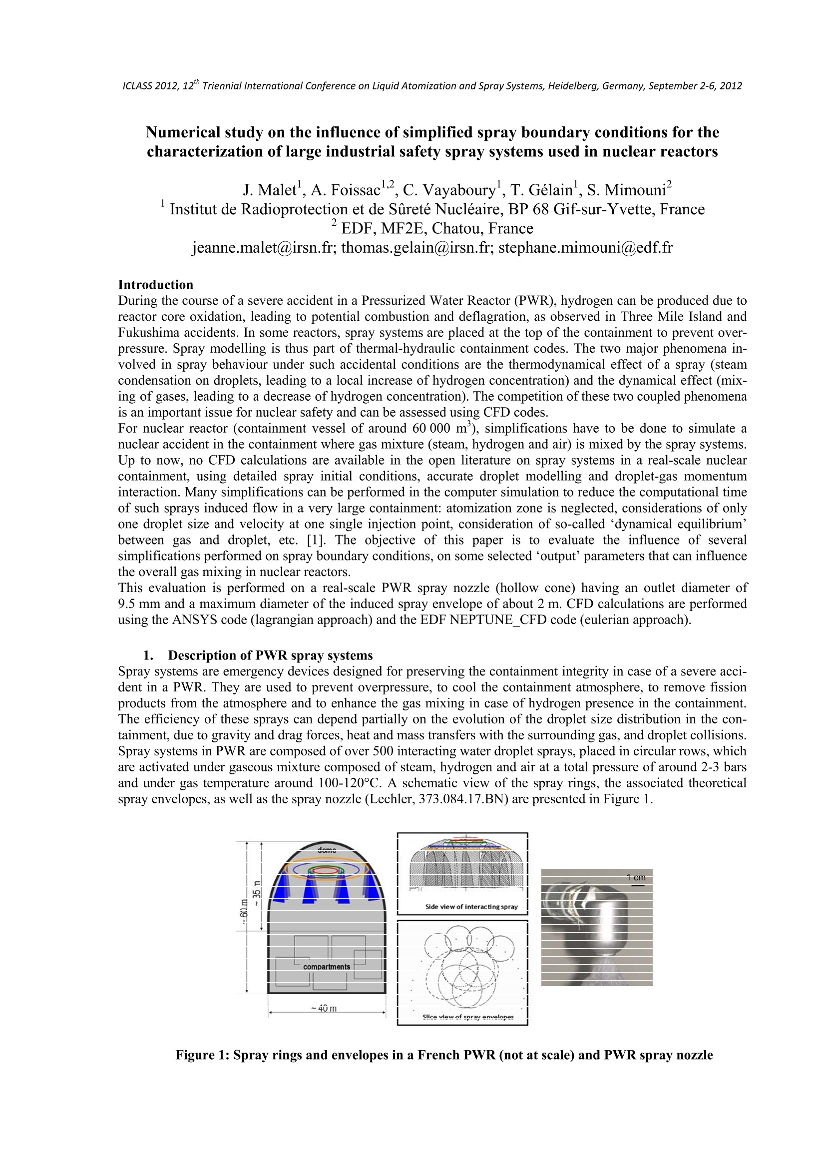
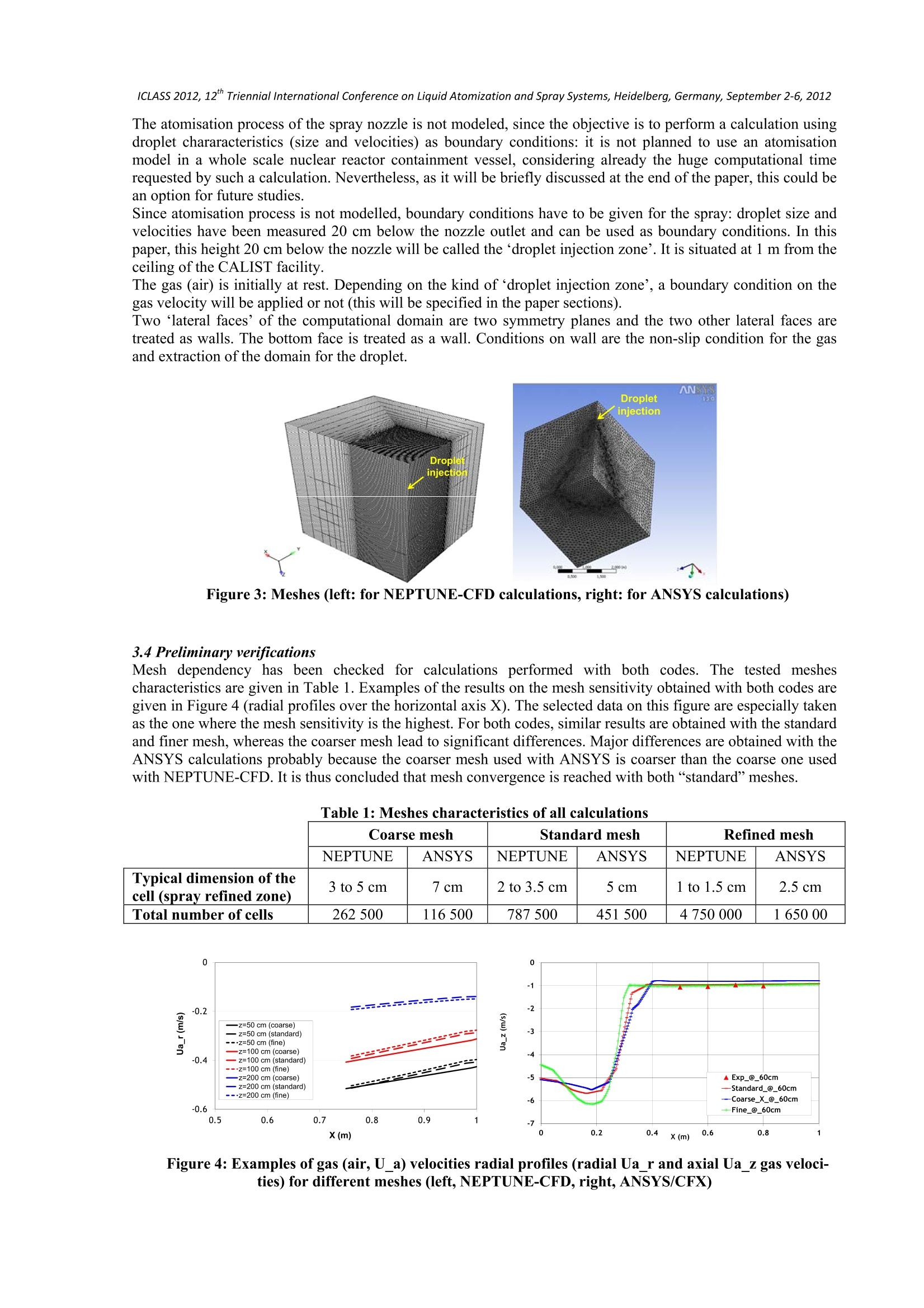
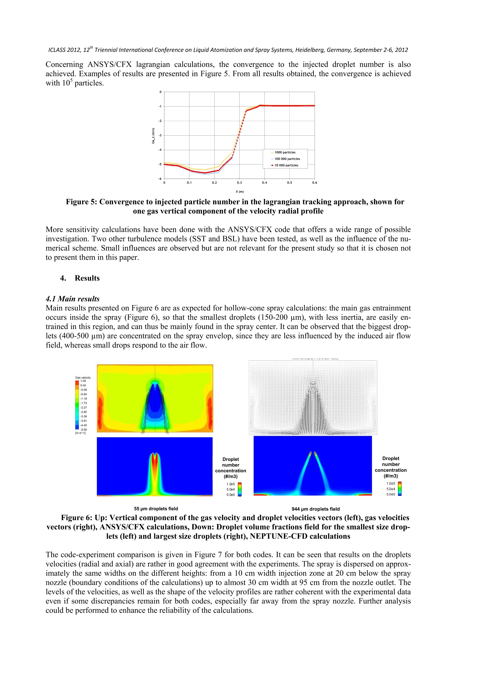
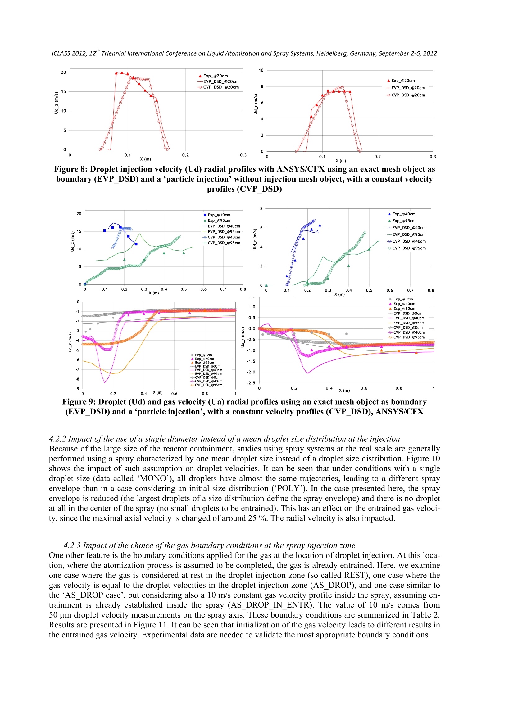
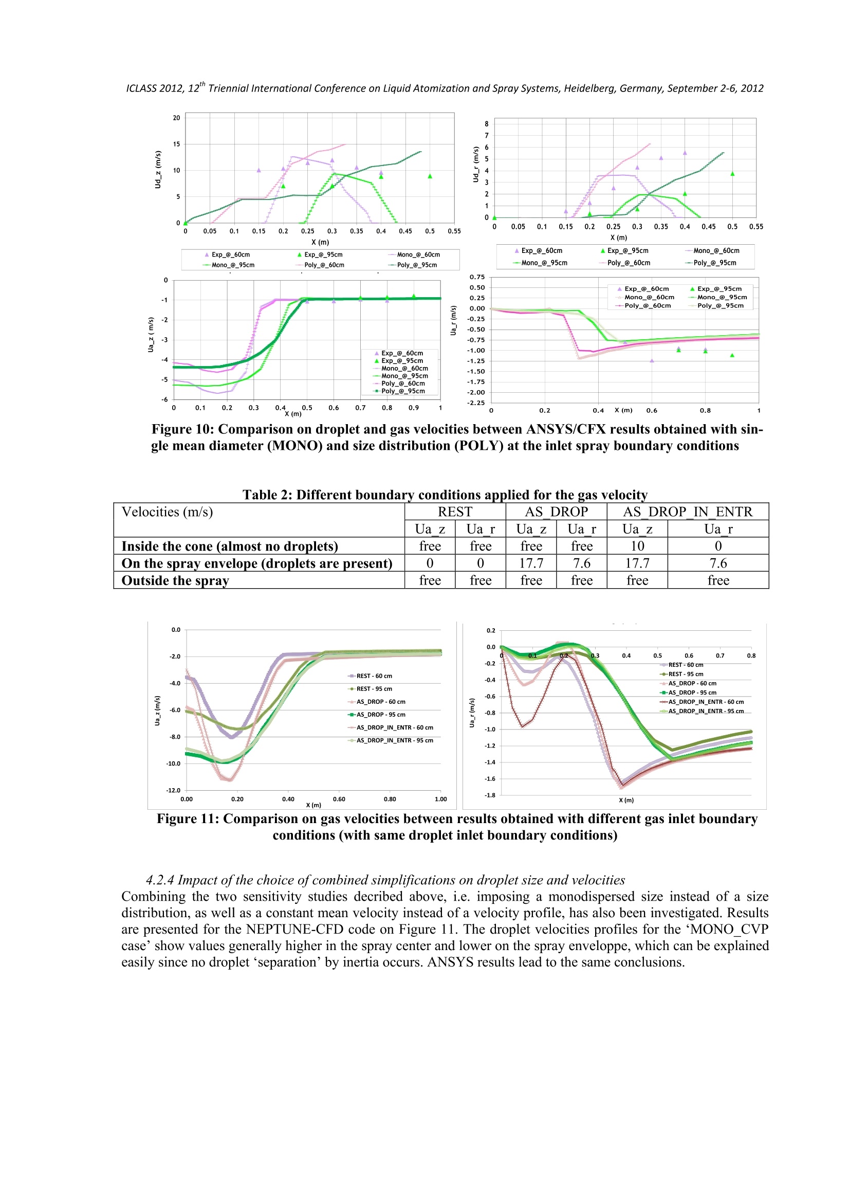
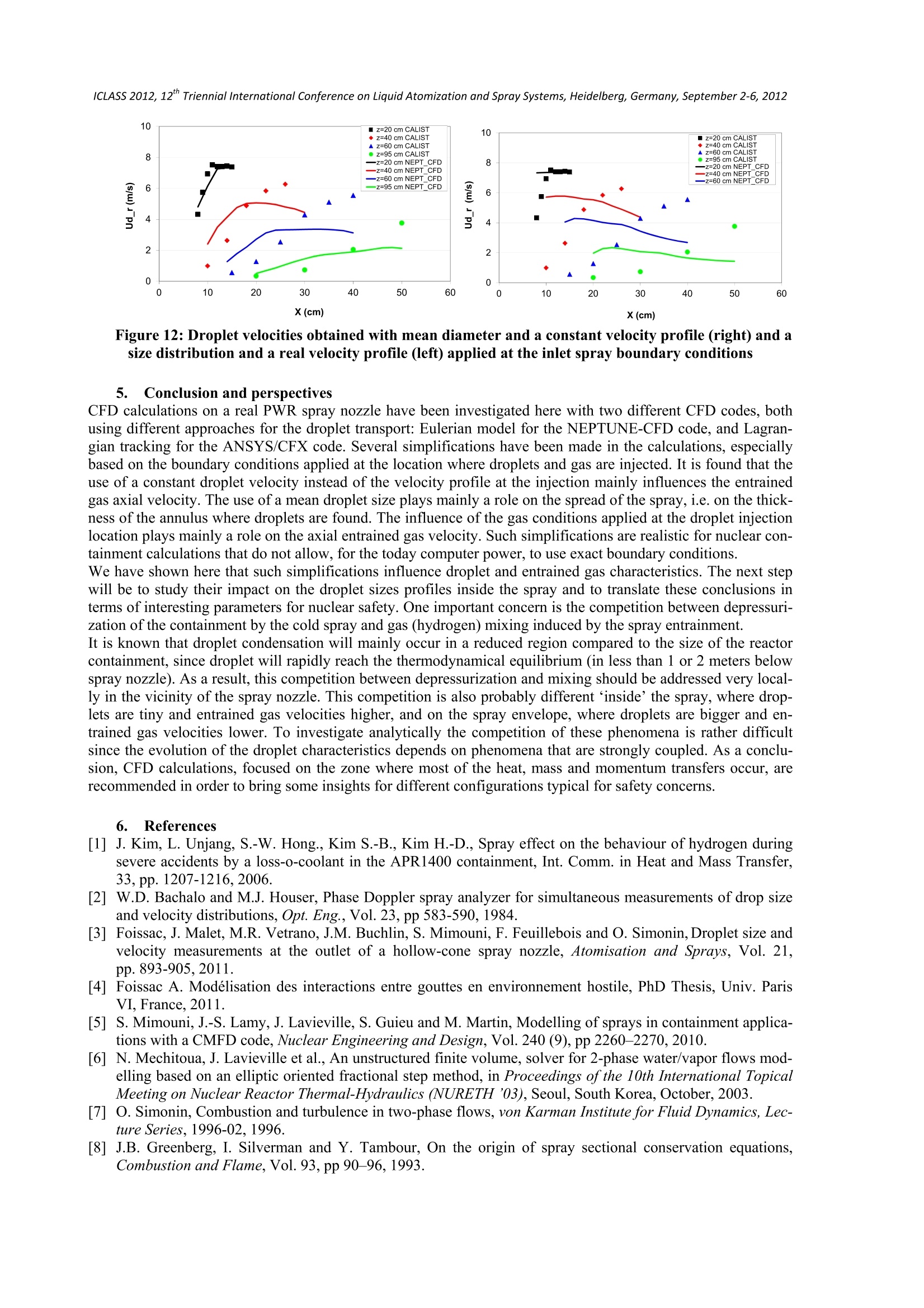
ICLASS 2012, 12”Triennial International Conference on Liquid Atomization and Spray Systems, Heidelberg, Germany, September 2-6, 2012 Numerical study on the influence of simplified spray boundary conditions for thecharacterization of large industrial safety spray systems used in nuclear reactors J. Malet’, A. Foissac 2, C. Vayaboury', T. Gelain , S. Mimouni Institut de Radioprotection et de Surete Nucleaire, BP 68 Gif-sur-Yvette, France EDF,MF2E, Chatou, France jeanne.malet@irsn.fr; thomas.gelain@irsn.fr;stephane.mimouni@edf.fr Introduction During the course of a severe accident in a Pressurized Water Reactor (PWR), hydrogen can be produced due toreactor core oxidation, leading to potential combustion and deflagration, as observed in Three Mile Island andFukushima accidents. In some reactors, spray systems are placed at the top of the containment to prevent over-pressure. Spray modelling is thus part of thermal-hydraulic containment codes. The two major phenomena in-volved in spray behaviour under such accidental conditions are the thermodynamical effect of a spray (steamcondensation on droplets, leading to a local increase of hydrogen concentration) and the dynamical effect (mix-ing of gases, leading to a decrease of hydrogen concentration). The competition of these two coupled phenomenais an important issue for nuclear safety and can be assessed using CFD codes. For nuclear reactor (containment vessel of around 60 000 m), simplifications have to be done to simulate anuclear accident in the containment where gas mixture (steam, hydrogen and air) is mixed by the spray systems.Up to now, no CFD calculations are available in the open literature on spray systems in a real-scale nuclearcontainment, using detailed spray initial conditions, accurate droplet modelling and droplet-gas momentuminteraction. Many simplifications can be performed in the computer simulation to reduce the computational timeof such sprays induced flow in a very large containment: atomization zone is neglected, considerations of onlyone droplet size and velocity at one single injection point, consideration of so-called ‘dynamical equilibrium’between gas and droplet, etc. [1]. The objective of this paper is to evaluate the influence of severalsimplifications performed on spray boundary conditions, on some selected output’parameters that can influencethe overall gas mixing in nuclear reactors. This evaluation is performed on a real-scale PWR spray nozzle (hollow cone) having an outlet diameter of9.5 mm and a maximum diameter of the induced spray envelope of about 2 m. CFD calculations are performedusing the ANSYS code (lagrangian approach) and the EDF NEPTUNE_CFD code (eulerian approach). 1..Description of PWR spray systems Spray systems are emergency devices designed for preserving the containment integrity in case of a severe acci-dent in a PWR. They are used to prevent overpressure, to cool the containment atmosphere, to remove fissionproducts from the atmosphere and to enhance the gas mixing in case of hydrogen presence in the containment.The efficiency of these sprays can depend partially on the evolution of the droplet size distribution in the con-tainment, due to gravity and drag forces, heat and mass transfers with the surrounding gas, and droplet collisions.Spray systems in PWR are composed of over 500 interacting water droplet sprays, placed in circular rows, whichare activated under gaseous mixture composed of steam, hydrogen and air at a total pressure of around 2-3 barsand under gas temperature around 100-120℃. A schematic view of the spray rings, the associated theoreticalspray envelopes, as well as the spray nozzle (Lechler, 373.084.17.BN) are presented in Figure 1. Figure 1: Spray rings and envelopes in a French PWR (not at scale) and PWR spray nozzle 2. Description of the experimental facility The experiments have been carried out at the Institut de Radioprotection et de Surete Nucleaire (IRSN), in theCALIST facility (Characterization and Application of Large and Industrial Spray Transfer, 160 m’) sketched inFigure 2. The set-up is composed of a hydraulic circuit supplying, for those experiments, a single spray nozzlewith a flow-rate of 1 1/s at a relative pressure of 3.5 bar. The pulverized water is collected in a 5 m’pool. Theaxial position of the spray nozzle can be changed using a monitored carriage. Figure 2: CALIST water-spray experimental facility Spray characteristics are measured by Phase-Doppler Interferometry (PDI, distributed by LAVISION/ARTIUM,Bachalo and Houser, 1984 [2]). In order to determine where atomization ends, i.e. where droplets are spherical,visualization has been performed with a Phantom high-speed camera.More information on these PWR spraymeasurements can be found in [3] and [4] where droplet sizes, droplet velocities and droplet size-velocities cor-relations are given. All measurements are performed in air under atmospheric conditions (1 bar,20°C). 3. Description of the numerical calculations 3.1 NEPTUNE-CFD code Numerical simulations have been performed using the NEPTUNE_CFD code (Mimouni et al.[5]). The solverbelongs to pressure based methods and is based on a finite volume discretization. It is able to simulate multi-component multiphase flows by solving a set of three balance equations for each field. The data structure is to-tally face-based which allows the use of arbitrary shaped cells including no conforming meshes. The main inter-est of the numerical method is the so-called “volume fraction - pressure - energy cycle”[6] that ensures massand energy conservation and allows strong interface source term coupling. In the simulations, gas turbulence isassociated to the k-e model, whereas dispersed phases turbulence is modelled with the Q2-Q12 model (Simonin[7]). The dispersed phase is considered as a set of continuous ‘fluid’media: each ‘fluid’corresponding to a sta-tistical average between two fixed droplet size (Greenberg et al. [8]). 3.2 ANSYS/FLUENT-CFX code The CFD code ANSYS 13, based on the conservative finite-volume method, is also used to calculate the gasflow induced by this PWR spray. Calculations are performed under incompressible, isothermal, steady-state andturbulent flow. The Lagrangian-droplet-Eulerian-fluid (LDEF) approach tracks the particle’s accelerations withNewton’s second law (gravity and drag forces) and imposes the particle-fluid (gas) interaction through a sourceterm (drag force) in the Navier-Stokes momentum equations. The standard k-e turbulence model is used here.CFX and FLUENT solvers are used for these calculations but mainly CFX results are presented here, since CFXhas a so-called‘hollow-cone’spray injection option. The obtained results lead us to test other spray injectionoptions. 3.3 Computational domain and boundary conditions The CALIST facility room is 7 m x 6 m large and 3.5 m height and the spray nozzle is placed at the center of ahorizontal slice of the room. Using symmetries, the computational domain is reduced to 1/4 of the CALISTfacility, so that it is 3 m x3.5 m large and 3.5 m height. The mesh is obtained using GAMBIT (structured-grid)for the NEPTUNE-CFD calculations, and using ANSYS-Meshing for the ANSYS/CFX calculations (unstruc-tured grid). Examples of the meshes are given on Figure 3. The way of mesh refinement used with both codes isdifferent: in the NEPTUNE-CFD calculations, the whole ‘spray zone’ is refined and in the ANSYS calculations,the expected spray enveloppe, assuming an angle of 60 degrees, is refined. The atomisation process of the spray nozzle is not modeled, since the objective is to perform a calculation usingdroplet chararacteristics (size and velocities) as boundary conditions: it is not planned to use an atomisationmodel in a whole scale nuclear reactor containment vessel, considering already the huge computational timerequested by such a calculation. Nevertheless, as it will be briefly discussed at the end of the paper, this could bean option for future studies. Since atomisation process is not modelled, boundary conditions have to be given for the spray: droplet size andvelocities have been measured 20 cm below the nozzle outlet and can be used as boundary conditions. In thispaper, this height 20 cm below the nozzle will be called the ‘droplet injection zone’. It is situated at 1 m from theceiling of the CALIST facility. The gas (air) is initially at rest. Depending on the kind of droplet injection zone’, a boundary condition on thegas velocity will be applied or not (this will be specified in the paper sections). Two “lateral faces’of the computational domain are two symmetry planes and the two other lateral faces aretreated as walls. The bottom face is treated as a wall. Conditions on wall are the non-slip condition for the gasand extraction of the domain for the droplet. Figure 3: Meshes (left: for NEPTUNE-CFD calculations, right: for ANSYS calculations) 3.4 Preliminary verifications Mesh dependency has been checked for calculations performed with both codes. The tested meshescharacteristics are given in Table 1. Examples of the results on the mesh sensitivity obtained with both codes aregiven in Figure 4 (radial profiles over the horizontal axis X). The selected data on this figure are especially takenas the one where the mesh sensitivity is the highest. For both codes, similar results are obtained with the standardand finer mesh, whereas the coarser mesh lead to significant differences. Major differences are obtained with theANSYS calculations probably because the coarser mesh used with ANSYS is coarser than the coarse one usedwith NEPTUNE-CFD. It is thus concluded that mesh convergence is reached with both“standard”meshes. Table 1: Meshes characteristics of all calculations Coarse mesh Standard mesh Refined mesh NEPTUNE ANSYS NEPTUNE ANSYS NEPTUNE ANSYS Typical dimension of thecell (spray refined zone) 3 to 5 cm 7cm 2 to3.5 cm 5 cm 1 to 1.5 cm 2.5 cm Total number of cells 262500 116500 787 500 451500 4750 000 1 650 00 Figure 4: Examples of gas (air, U_a) velocities radial profiles (radial Ua_r and axial Ua z gas veloci-ties) for different meshes (left, NEPTUNE-CFD,right, ANSYS/CFX) Concerning ANSYS/CFX lagrangian calculations, the convergence to the injected droplet number is alsoachieved. Examples of results are presented in Figure 5. From all results obtained, the convergence is achievedwith 10'particles. Figure 5: Convergence to injected particle number in the lagrangian tracking approach, shown forone gas vertical component of the velocity radial profile More sensitivity calculations have been done with the ANSYS/CFX code that offers a wide range of possibleinvestigation. Two other turbulence models (SST and BSL) have been tested, as well as the influence of the nu-merical scheme. Small influences are observed but are not relevant for the present study so that it is chosen notto present them in this paper. 4. Results 4.1 Main results Main results presented on Figure 6 are as expected for hollow-cone spray calculations: the main gas entrainmentoccurs inside the spray (Figure 6), so that the smallest droplets (150-200 um), with less inertia, are easily en-trained in this region, and can thus be mainly found in the spray center. It can be observed that the biggest drop-lets (400-500 um) are concentrated on the spray envelop, since they are less influenced by the induced air flowfield, whereas small drops respond to the air flow. 55 pm droplets field 944 pm droplets field Figure 6: Up: Vertical component of the gas velocity and droplet velocities vectors (left), gas velocitiesvectors (right),ANSYS/CFX calculations, Down: Droplet volume fractions field for the smallest size drop-lets (left) and largest size droplets (right),NEPTUNE-CFD calculations The code-experiment comparison is given in Figure 7 for both codes. It can be seen that results on the dropletsvelocities (radial and axial) are rather in good agreement with the experiments. The spray is dispersed on approx-imately the same widths on the different heights: from a 10 cm width injection zone at 20 cm below the spraynozzle (boundary conditions of the calculations) up to almost 30 cm width at 95 cm from the nozzle outlet. Thelevels of the velocities, as well as the shape of the velocity profiles are rather coherent with the experimental dataeven if some discrepancies remain for both codes, especially far away from the spray nozzle. Further analysiscould be performed to enhance the reliability of the calculations. X(m) Figure 7: Droplet axial (left) and radial (right) velocity profiles at different distances from the spray noz-zle, ANSYS-CFX (up) and NEPTUNE-CFD (down) versus CALIST experiments 4.2 Studies on the effect ofsimplified spray boundary conditions In nuclear reactor applications, considering the large volume (60000 m’) and the important number of variousphenomena to be simulated to represent accidental conditions, some simplifications have to be made. Here, so-called ‘simplifications studies’ in which simplified conditions are used for the calculations, are performed inorder to see their impact on the results. Most of the simplifications studies have been performed using theANSYS/CFX code, even if NEPTUNE-CFD results lead, as we will see on section 4.2.4, to similar conclusions. 4.2.1 Impact of the use ofa constant velocity profile at the injection In the results presented above, the exact experimental droplet size distribution and velocity profiles have beenused as boundary conditions for the droplets, imposing the creation of a mesh object that define droplet ‘inlet’conditions (see curves at 20 cm in Figure 7). However, for lagrangian tracking of commercial codes, severaldifferent ‘particle injections’are proposed for the user: these particle injections’give the interesting possibilitynot to model this ‘inlet’zone. This can be very useful for CFD calculations of spray systems in a nuclear reactorcontainment, since the mesh of such a small region regarding to the size of the containment would be a greatconstraint. For example, plain-orifice atomizer, pressure-swirl-atomizer, flat-fan atomizer, full-cone, ring coneand hollow-cone are ‘particle injections’available in ANSYS. The ring’cone “particle injection’of CFX has been tested here, since the PWR spray characteristics obtainedexperimentally at 20 cm are found to be over an annulus ring. In such ‘ring cone'calculation, the input data thatlead to the closest droplet initial velocities profiles (at 20 cm) is the one considering a ring from 10 to 13 cm(instead of 8.5 cm to 14.5 cm), having an angle of 25 degrees (30 degrees is the angle at the middle position inthe ring), and using an amplitude for the droplet velocity of 18 m/s. The droplet sizes are modelled with theexperimental size distribution presented in Foissac et al. [3] (data called CVP_DSD for Constant Velocity Profileand Droplet Size distribution). They are compared with the data presented in Figure 7 having the exactexperimental injection velocity profile (data called EVP_DSD, EVP stands for Experimental Velocity Profile). Itcan be seen on Figure 10f8 that at boundary conditions (20 cm), the droplet velocities (curves CVP) are not exactlyfitting the measured experimental data using such ‘ring cone particle injection’due to the interpolation of theimposed data with the mesh (whereas with an inlet model, the experimental conditions can be applied perfectlyto the boudary zone). The consequences of these different boundary conditions are shown on Figure 9 at 40 and95 cm from the nozzle outlet: the droplet dispersion, the droplet gas velocities, and the entrained gas velocitiesare not the same. For example, the maximum value of the axial velocity is changed of 50 %. Figure 8:Droplet injection velocity (Ud) radial profiles with ANSYS/CFX using an exact mesh object asboundary (EVP_DSD) and a ‘particle injection’without injection mesh object, with a constant velocityprofiles (CVP_DSD) Figure 9: Droplet (Ud) and gas velocity (Ua) radial profiles using an exact mesh object as boundary(EVP_DSD) and a ‘particle injection’, with a constant velocity profiles (CVP_DSD), ANSYS/CFX 4.2.2 Impact of the use ofa single diameter instead ofa mean droplet size distribution at the injectionBecause of the large size of the reactor containment, studies using spray systems at the real scale are generallyperformed using a spray characterized by one mean droplet size instead of a droplet size distribution. Figure 10shows the impact of such assumption on droplet velocities. It can be seen that under conditions with a singledroplet size (data calledMONO’), all droplets have almost the same trajectories, leading to a different sprayenvelope than in a case considering an initial size distribution (POLY’). In the case presented here, the sprayenvelope is reduced (the largest droplets of a size distribution define the spray envelope) and there is no dropletat all in the center of the spray (no small droplets to be entrained). This has an effect on the entrained gas veloci-ty, since the maximal axial velocity is changed of around 25 %. The radial velocity is also impacted. 4.2.3 Impact of the choice of the gas boundary conditions at the spray injection zone One other feature is the boundary conditions applied for the gas at the location of droplet injection. At this loca-tion, where the atomization process is assumed to be completed, the gas is already entrained. Here, we examineone case where the gas is considered at rest in the droplet injection zone (so called REST), one case where thegas velocity is equal to the droplet velocities in the droplet injection zone (AS_DROP), and one case similar tothe ‘AS_DROP case’, but considering also a 10 m/s constant gas velocity profile inside the spray, assuming en-trainment is already established inside the spray (AS_DROP_IN_ENTR). The value of 10 m/s comes from50 um droplet velocity measurements on the spray axis. These boundary conditions are summarized in Table 2.Results are presented in Figure 11. It can be seen that initialization of the gas velocity leads to different results inthe entrained gas velocity. Experimental data are needed to validate the most appropriate boundary conditions. Figure 10: Comparison on droplet and gas velocities between ANSYS/CFX results obtained with sin-gle mean diameter (MONO) and size distribution (POLY) at the inlet spray boundary conditions Table 2: Different boundary conditions applied for the gas velocity Velocities (m/s) REST AS DROP AS DROP IN ENTR Ua z Uar Ua z Uar Ua z Ua r Inside the cone (almost no droplets) free free free free 10 0 On the spray envelope (droplets are present) 0 0 17.7 7.6 17.7 7.6 Outside the spray free free free free free free Figure 11: Comparison on gas velocities between results obtained with different gas inlet boundaryconditions (with same droplet inlet boundary conditions) 4.2.4 Impact of the choice of combined simplifications on droplet size and velocitiesCombining the two sensitivity studies decribed above, i.e. imposing a monodispersed size instead of a sizedistribution, as well as a constant mean velocity instead of a velocity profile, has also been investigated. Resultsare presented for the NEPTUNE-CFD code on Figure 11. The droplet velocities profiles for the ‘MONO CVPcase’show values generally higher in the spray center and lower on the spray enveloppe, which can be explainedeasily since no droplet‘separation’by inertia occurs. ANSYS results lead to the same conclusions. X(cm) Figure 12: Droplet velocities obtained with mean diameter and a constant velocity profile (right) and asize distribution and a real velocity profile (left) applied at the inlet spray boundary conditions 5.Conclusion and perspectives CFD calculations on a real PWR spray nozzle have been investigated here with two different CFD codes, bothusing different approaches for the droplet transport: Eulerian model for the NEPTUNE-CFD code, and Lagran-gian tracking for the ANSYS/CFX code. Several simplifications have been made in the calculations, especiallybased on the boundary conditions applied at the location where droplets and gas are injected. It is found that theuse of a constant droplet velocity instead of the velocity profile at the injection mainly influences the entrainedgas axial velocity. The use of a mean droplet size plays mainly a role on the spread of the spray, i.e. on the thick-ness of the annulus where droplets are found. The influence of the gas conditions applied at the droplet injectionlocation plays mainly a role on the axial entrained gas velocity. Such simplifications are realistic for nuclear con-tainment calculations that do not allow, for the today computer power, to use exact boundary conditions.We have shown here that such simplifications influence droplet and entrained gas characteristics. The next step will be to study their impact on the droplet sizes profiles inside the spray and to translate these conclusions interms of interesting parameters for nuclear safety. One important concern is the competition between depressuri-zation of the containment by the cold spray and gas (hydrogen) mixing induced by the spray entrainment. It is known that droplet condensation will mainly occur in a reduced region compared to the size of the reactorcontainment, since droplet will rapidly reach the thermodynamical equilibrium (in less than 1 or 2 meters belowspray nozzle). As a result, this competition between depressurization and mixing should be addressed very local-ly in the vicinity of the spray nozzle. This competition is also probably different ‘inside’the spray, where drop-lets are tiny and entrained gas velocities higher, and on the spray envelope, where droplets are bigger and en-trained gas velocities lower. To investigate analytically the competition of these phenomena is rather difficultsince the evolution of the droplet characteristics depends on phenomena that are strongly coupled. As a conclu-sion, CFD calculations, focused on the zone where most of the heat, mass and momentum transfers occur, arerecommended in order to bring some insights for different configurations typical for safety concerns. ( 6. References ) [1]J. Kim, L. Unjang, S.-W. Hong.,Kim S.-B., Kim H.-D., Spray effect on the behaviour of hydrogen duringsevere accidents by a loss-o-coolant in the APR1400 containment, Int. Comm. in Heat and Mass Transfer,33,pp. 1207-1216,2006. 2W.D. Bachalo and M.J. Houser, Phase Doppler spray analyzer for simultaneous measurements of drop sizeand velocity distributions,Opt. Eng.,Vol. 23, pp 583-590,1984 [31Foissac, J. Malet, M.R. Vetrano, J.M. Buchlin, S. Mimouni, F. Feuillebois and O. Simonin,Droplet size andvelocity measurements at the outlet of a hollow-cone spray nozzle, Atomisation and Sprays, Vol. 21,pp.893-905,2011. ( 4] F oissac A . M odelisation des interactions entre gouttes en environnement h ostile, PhD T hesis, U niv. P aris VI, France, 2011. ) ( [5 ] S . M imouni, J.-S. Lamy,J. L a vieville,S. Guieu and M. Martin, Modelling of sprays in containment applica-tions with a CMFD code, Nuclear Engineering and Design, Vol. 240 (9), pp 226 0 -2270,2010. ) [6]N. Mechitoua, J. Lavieville et al., An unstructured finite volume, solver for 2-phase water/vapor flows mod-elling based on an elliptic oriented fractional step method, in Proceedings ofthe 10th International TopicalMeeting on Nuclear Reactor Thermal-Hydraulics (NURETH '03), Seoul, South Korea, October, 2003. ( [7] O .Si m onin, Combustion and turbulence in two- p hase flows, von Karman Institute for F l uid Dynamics, Lec-ture Series, 1996-02 , 1996. ) ( [8] J .B. Greenberg, I . Silverman a nd Y. Tambour, On the origin of sp r ay se c tional conservation e q uations,. Combustion and Flame, Vol. 93, pp 90-96, 1993. ) During the course of a severe accident in a Pressurized Water Reactor (PWR), hydrogen can be produced due to reactor core oxidation, leading to potential combustion and deflagration, as observed in Three Mile Island and Fukushima accidents. In some reactors, spray systems are placed at the top of the containment to prevent overpressure. Spray modelling is thus part of thermal-hydraulic containment codes. The two major phenomena involved in spray behaviour under such accidental conditions are the thermodynamical effect of a spray (steamcondensation on droplets, leading to a local increase of hydrogen concentration) and the dynamical effect (mixing of gases, leading to a decrease of hydrogen concentration). The competition of these two coupled phenomena is an important issue for nuclear safety and can be assessed using CFD codes. For nuclear reactor (containment vessel of around 60 000 m3), simplifications have to be done to simulate a nuclear accident in the containment where gas mixture (steam, hydrogen and air) is mixed by the spray systems. Up to now, no CFD calculations are available in the open literature on spray systems in a real-scale nuclearcontainment, using detailed spray initial conditions, accurate droplet modelling and droplet-gas momentum interaction. Many simplifications can be performed in the computer simulation to reduce the computational time of such sprays induced flow in a very large containment: atomization zone is neglected, considerations of only one droplet size and velocity at one single injection point, consideration of so-called ‘dynamical equilibrium’ between gas and droplet, etc. [1]. The objective of this paper is to evaluate the influence of several simplifications performed on spray boundary conditions, on some selected ‘output’ parameters that can influence the overall gas mixing in nuclear reactors.This evaluation is performed on a real-scale PWR spray nozzle (hollow cone) having an outlet diameter of 9.5 mm and a maximum diameter of the induced spray envelope of about 2 m. CFD calculations are performed using the ANSYS code (lagrangian approach) and the EDF NEPTUNE_CFD code (eulerian approach).
确定


还剩6页未读,是否继续阅读?

产品配置单

北京欧兰科技发展有限公司为您提供《大型工业安全喷雾系统中喷雾液滴粒径和速度检测方案(激光干涉仪)》,该方案主要用于其他中喷雾液滴粒径和速度检测,参考标准--,《大型工业安全喷雾系统中喷雾液滴粒径和速度检测方案(激光干涉仪)》用到的仪器有激光相位多普勒干涉仪LDV,PDI,PDPA,PDA
推荐专场


相关方案
更多
该厂商其他方案
更多