
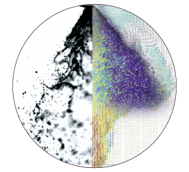


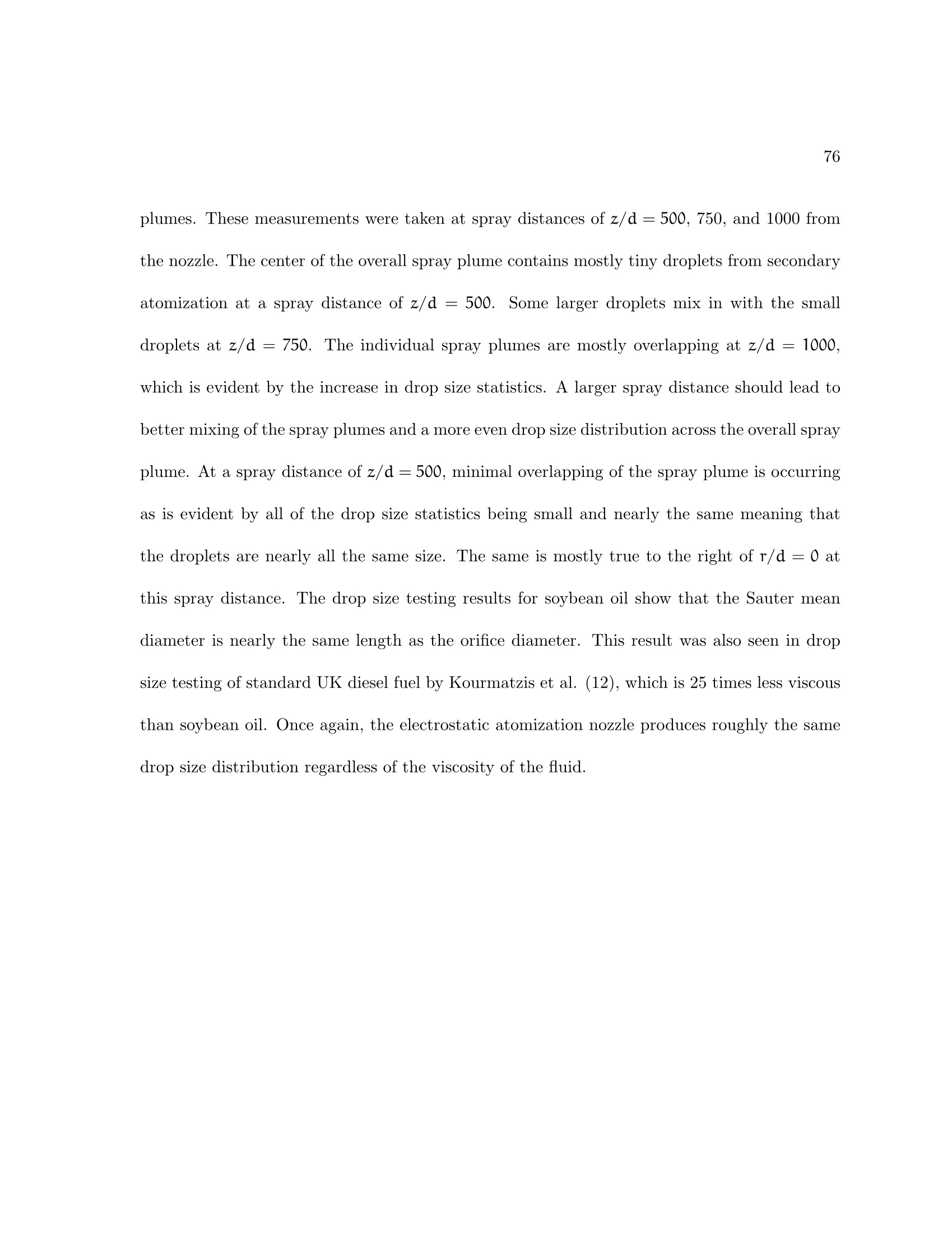
采用LaVision公司基于成像测量的SprayMaster和Artium公司相位多普勒粒子干涉仪对植物油的但喷嘴和多喷嘴静电雾化过程进行了全局几何参量测量和单点喷雾液滴运动的二维速度和液滴粒径测量。
方案详情

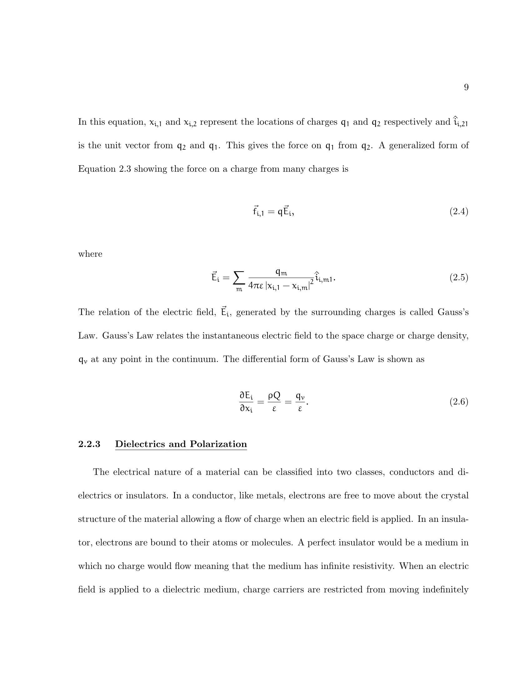
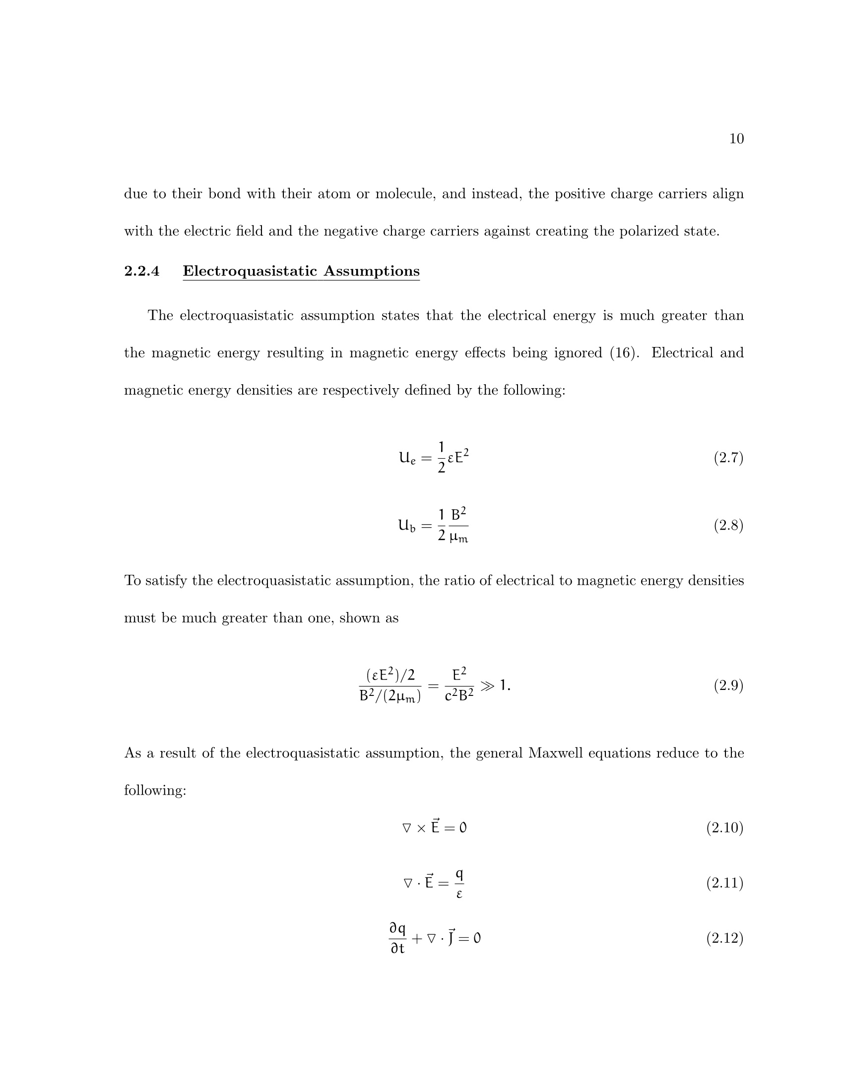
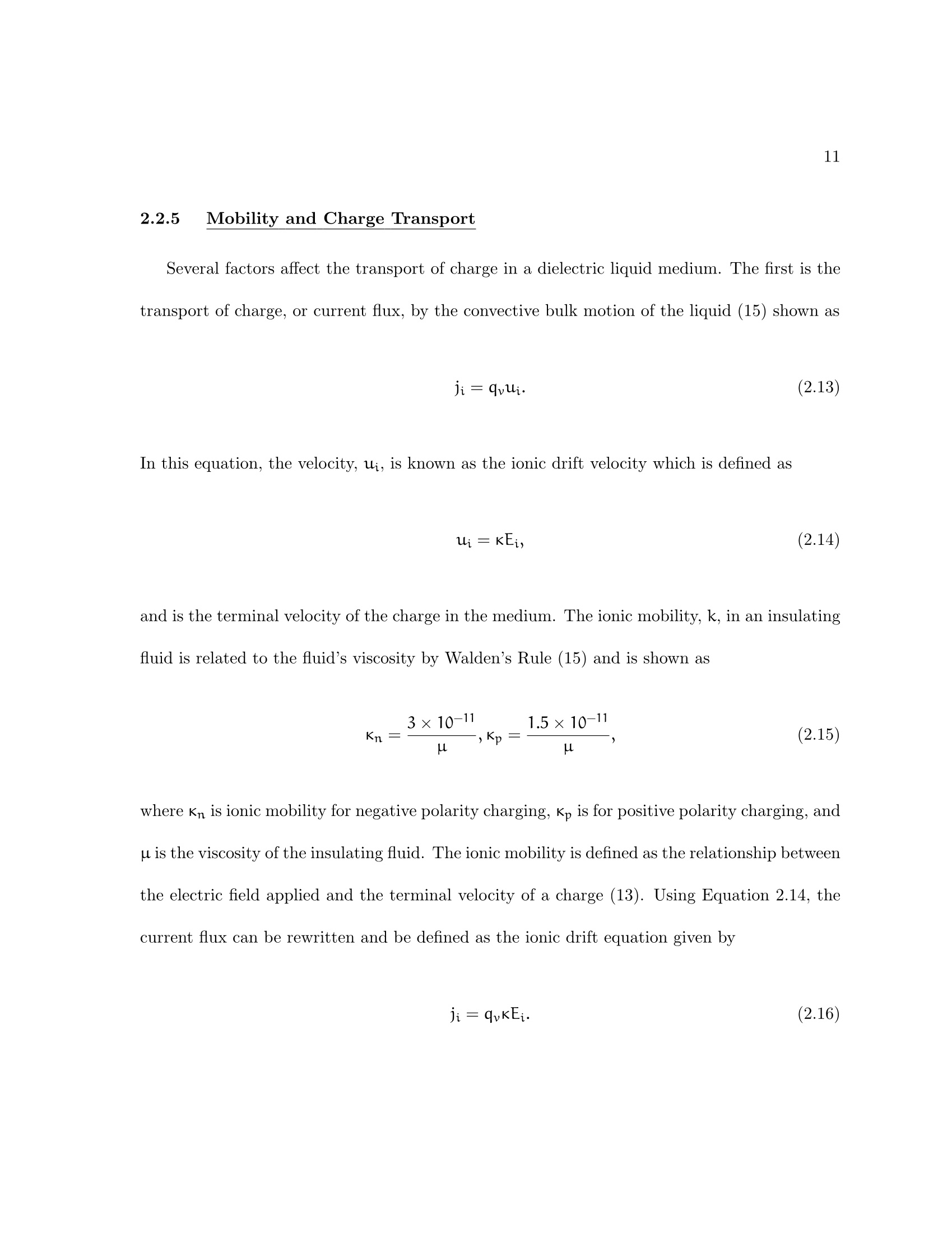
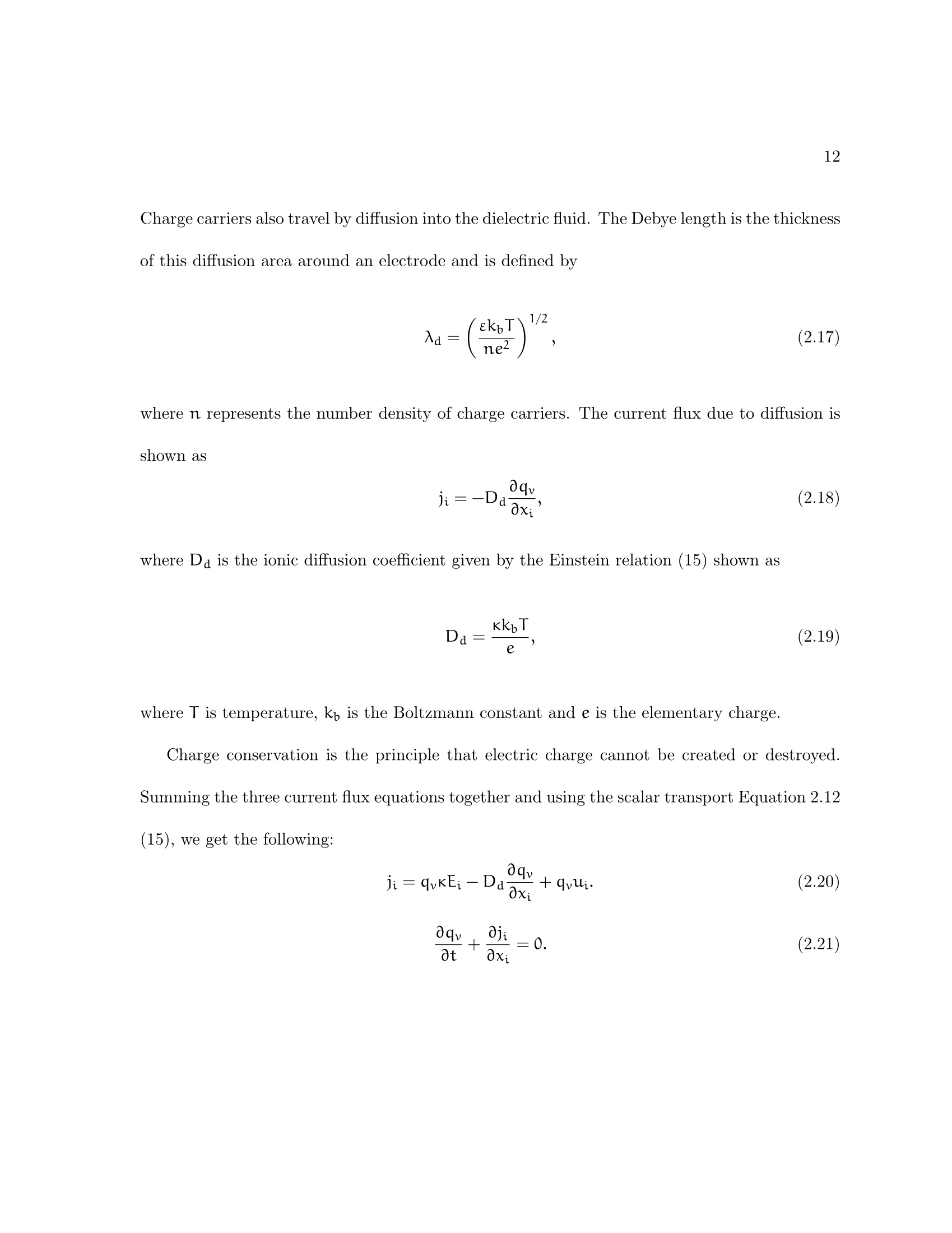
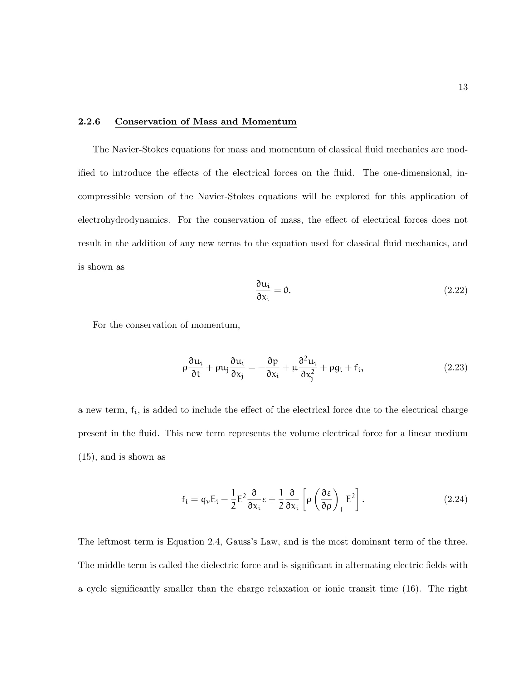
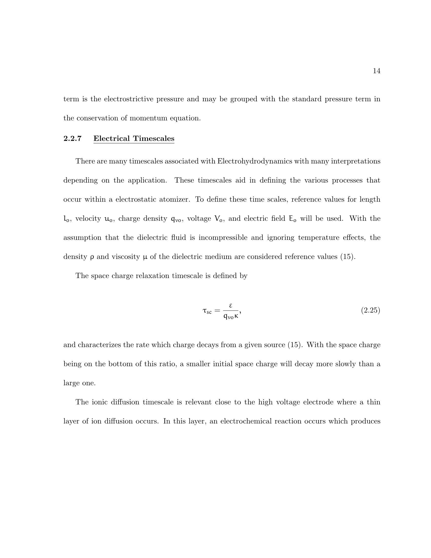
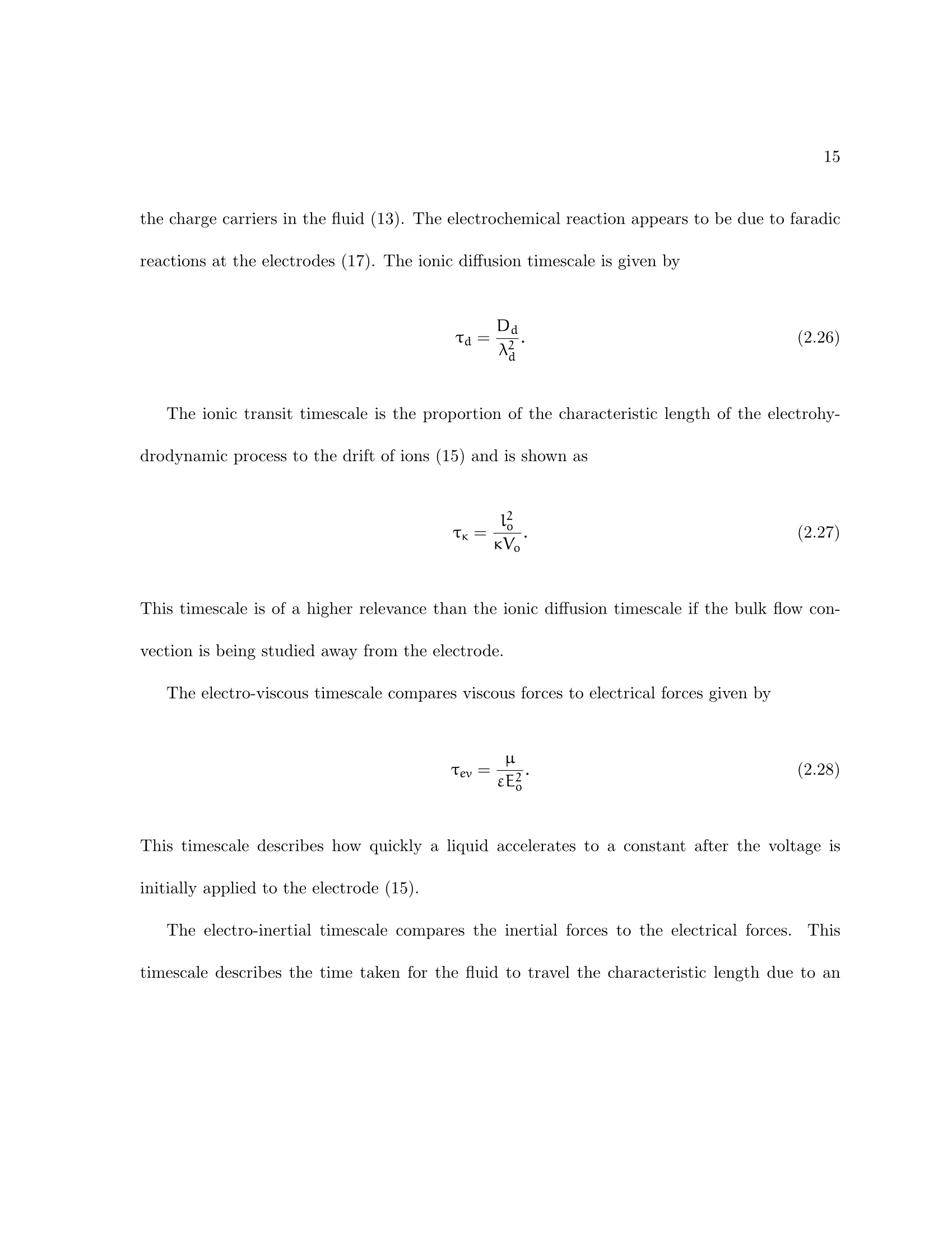
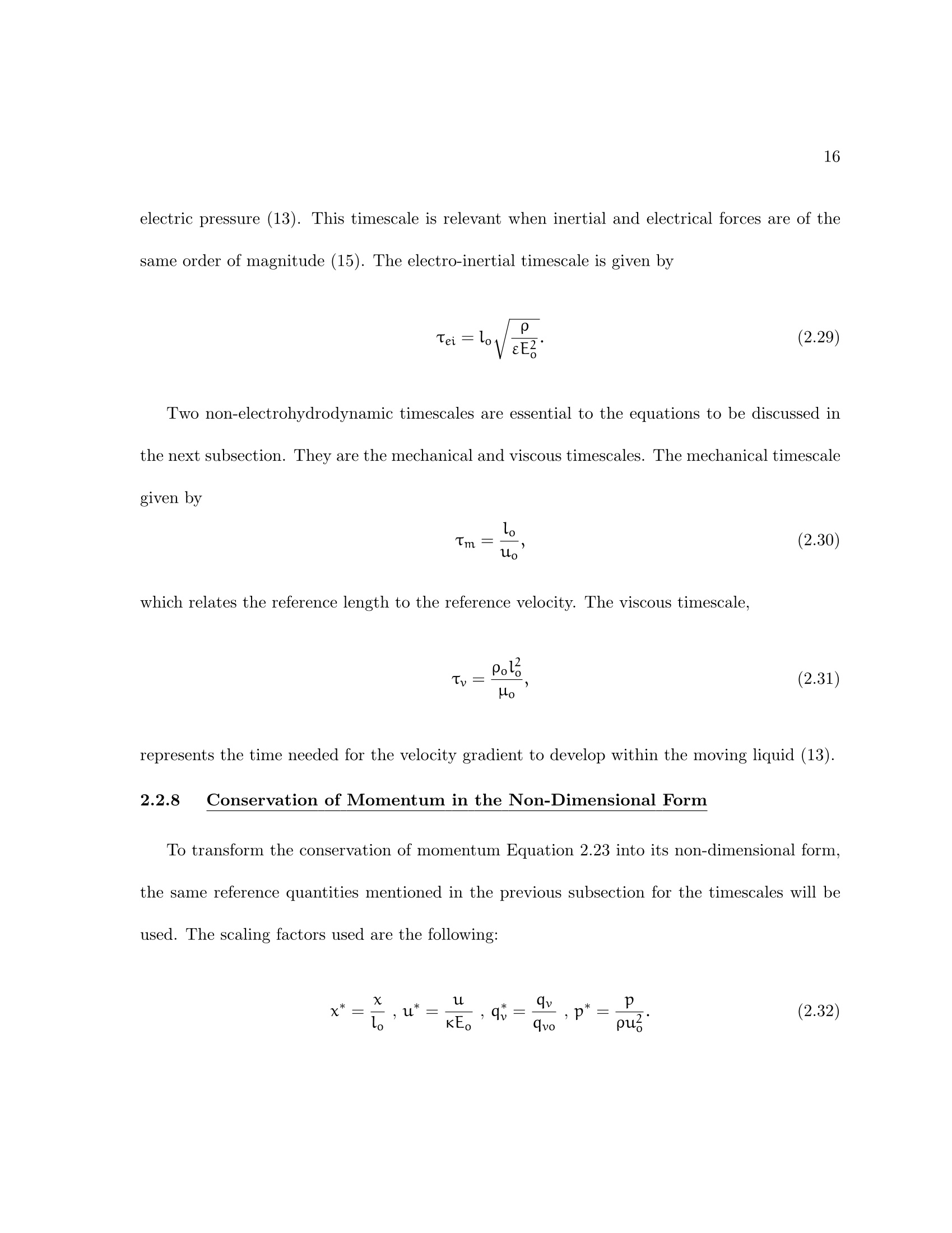
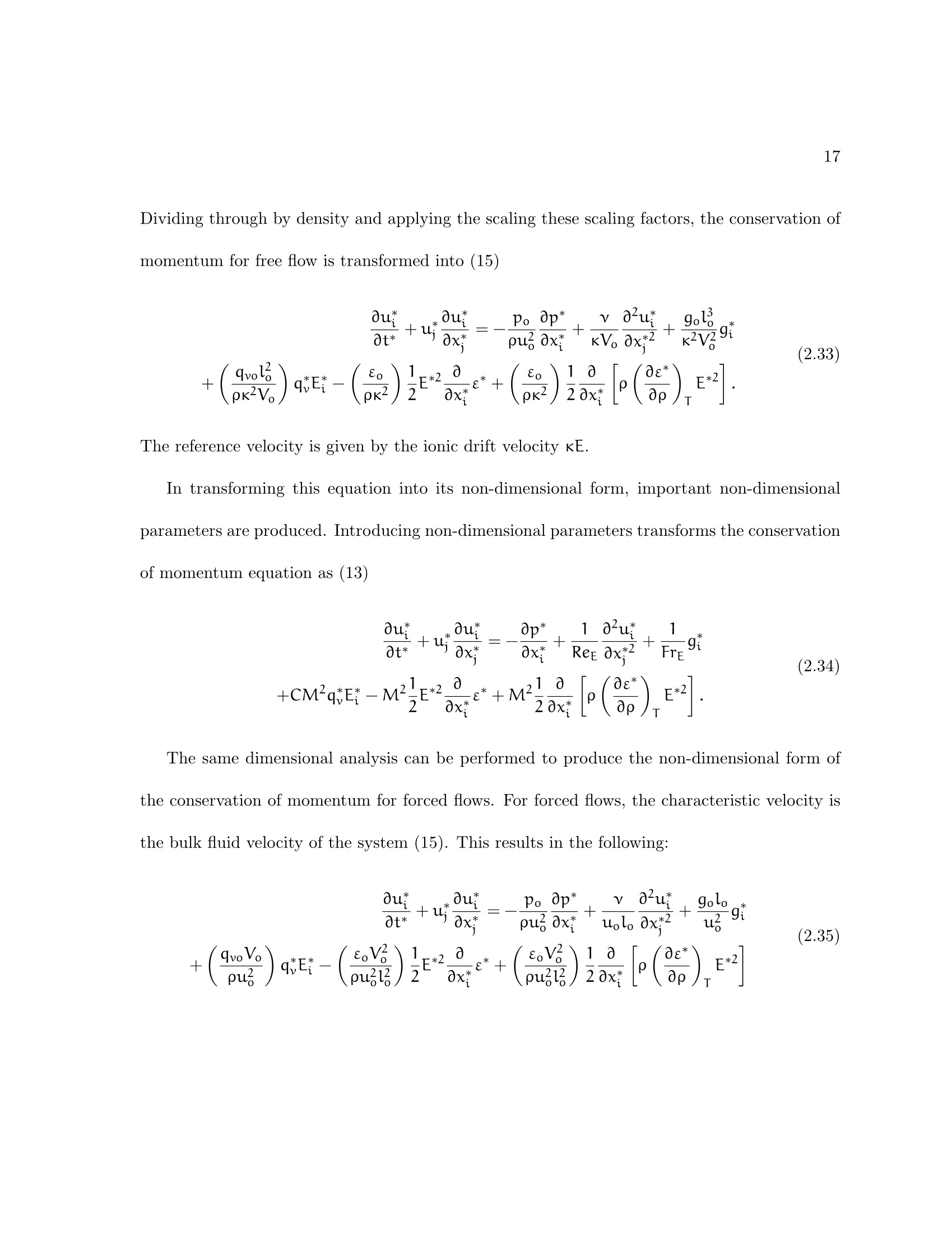
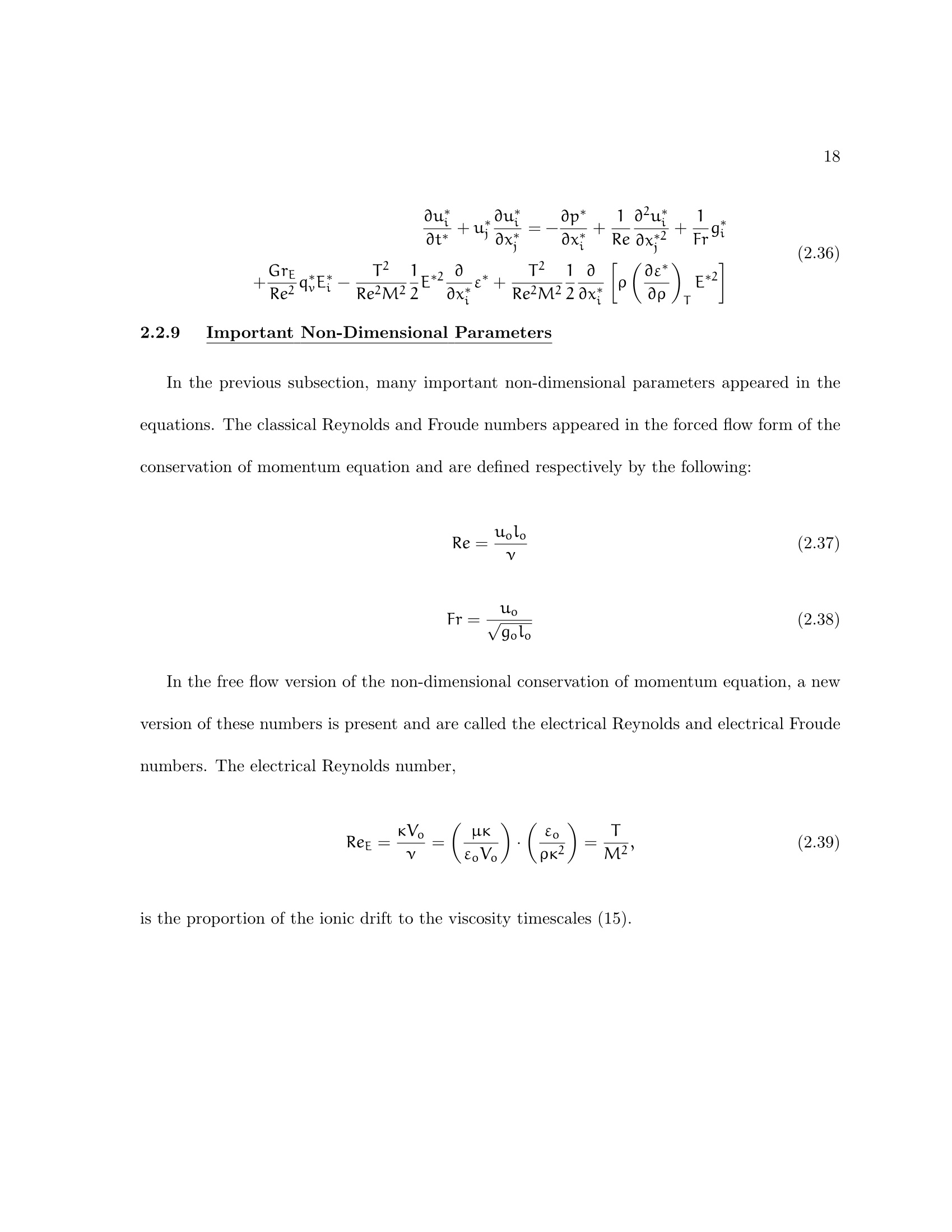
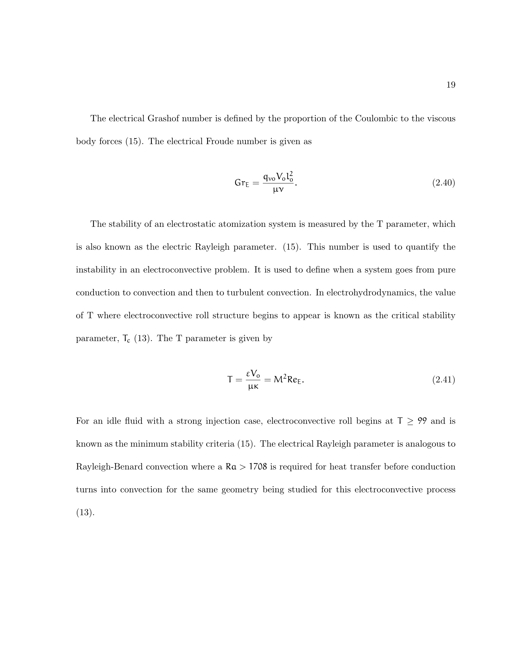
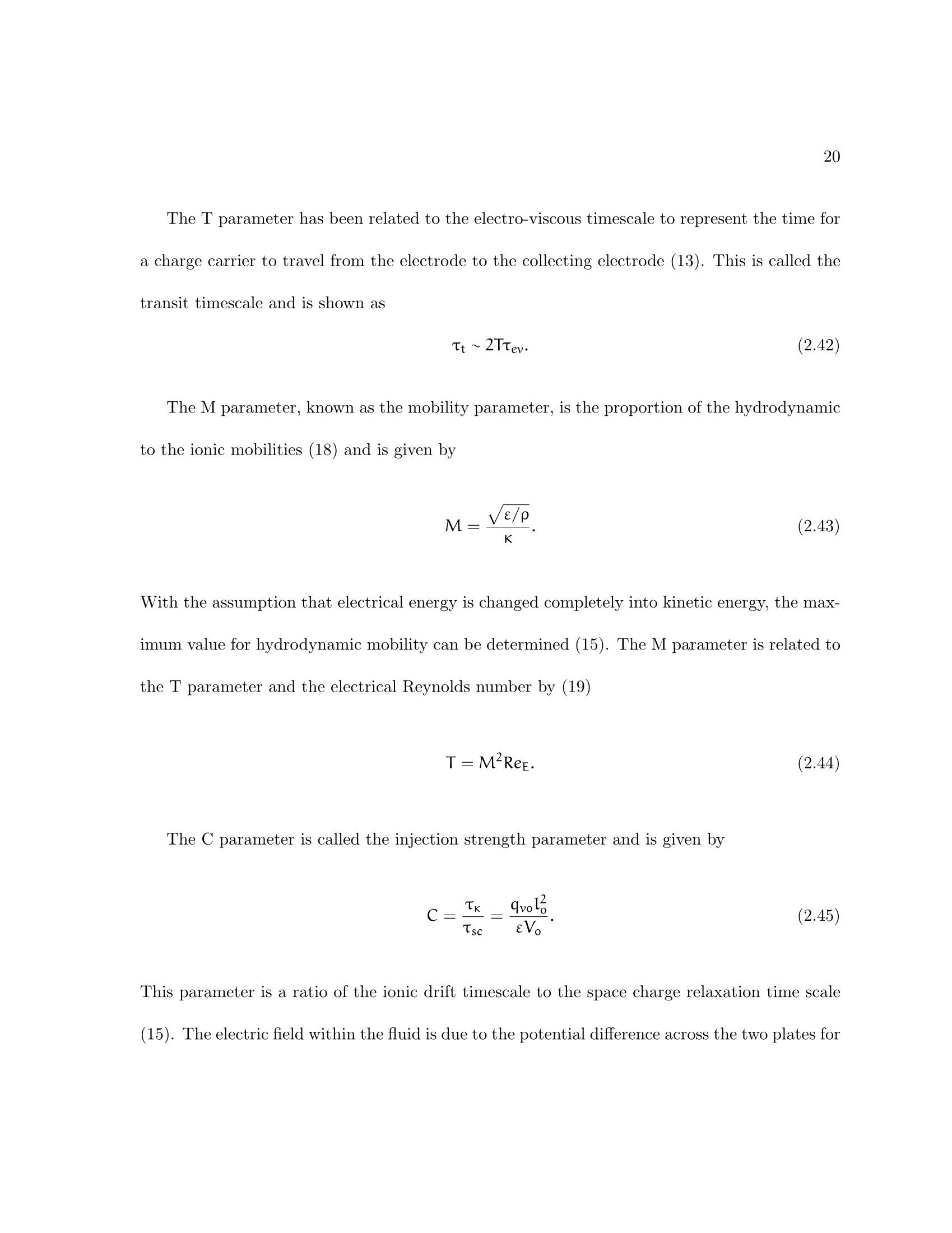
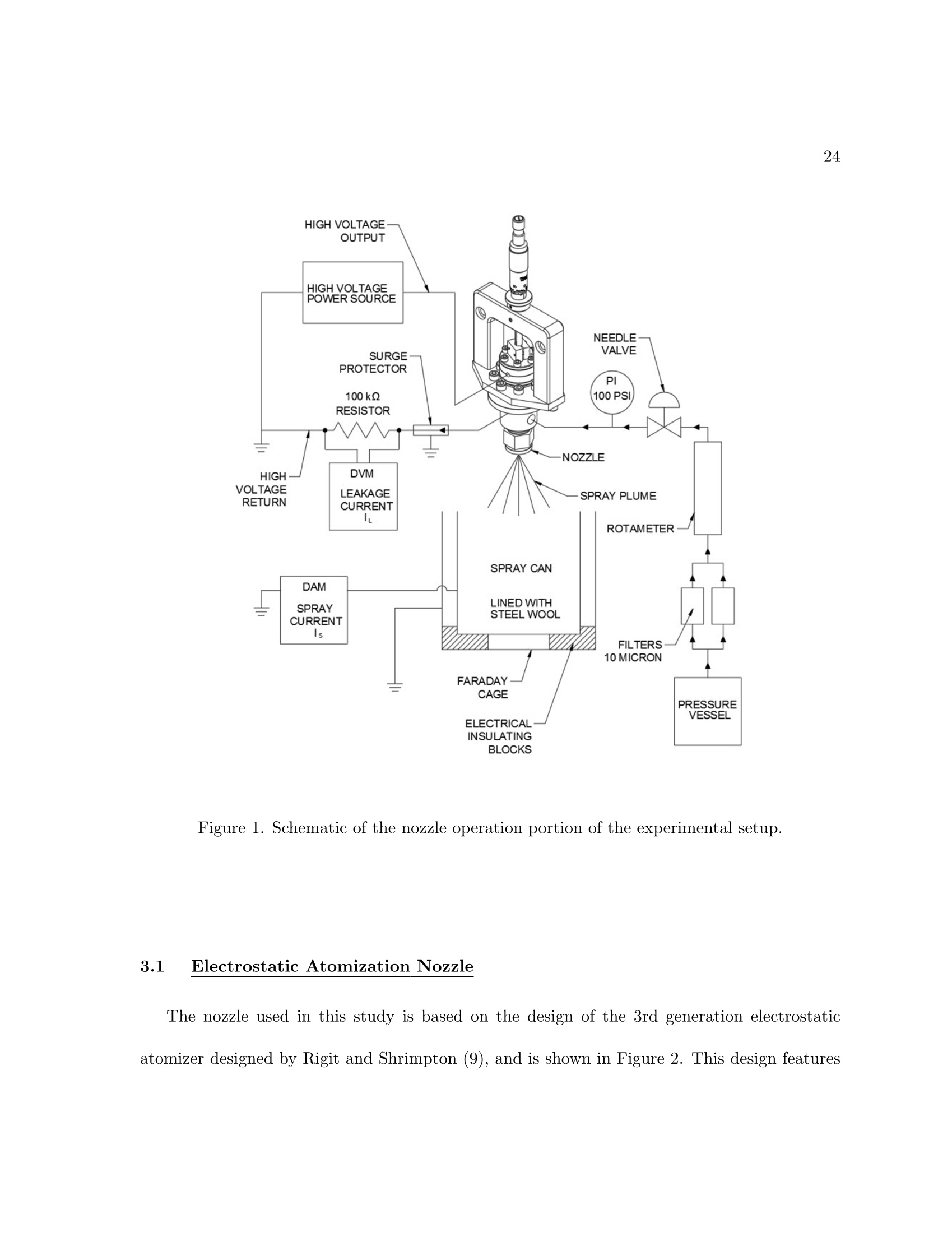
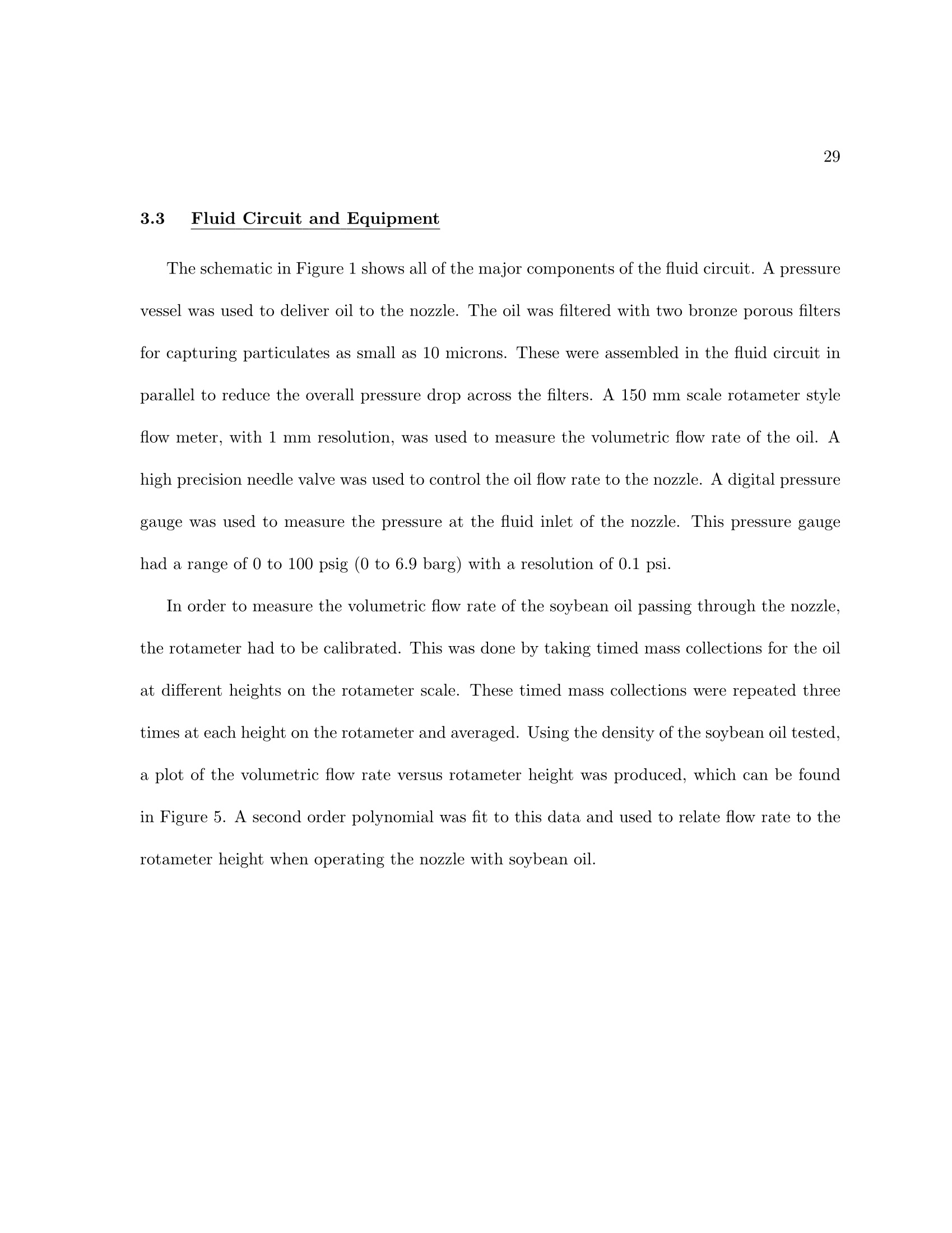
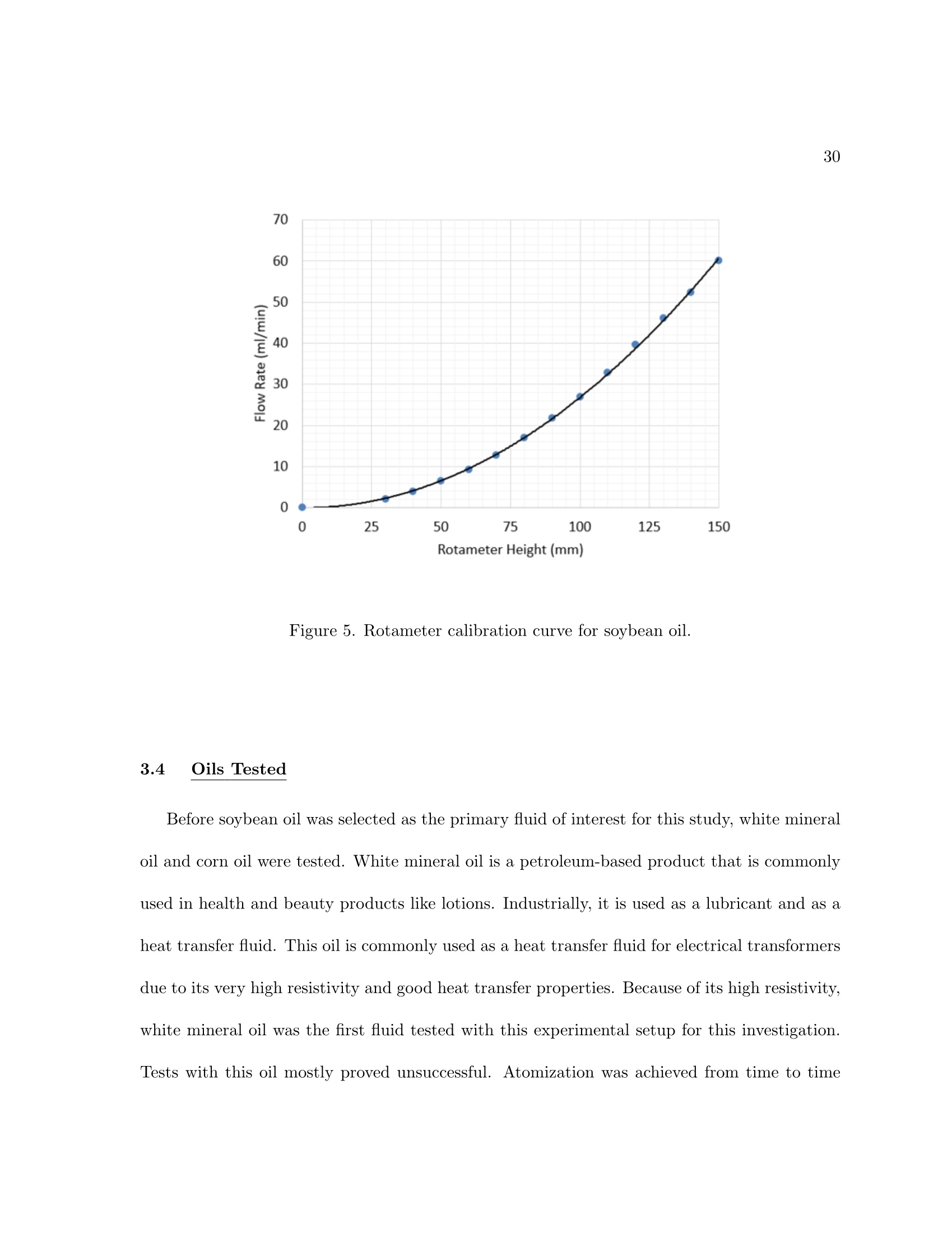
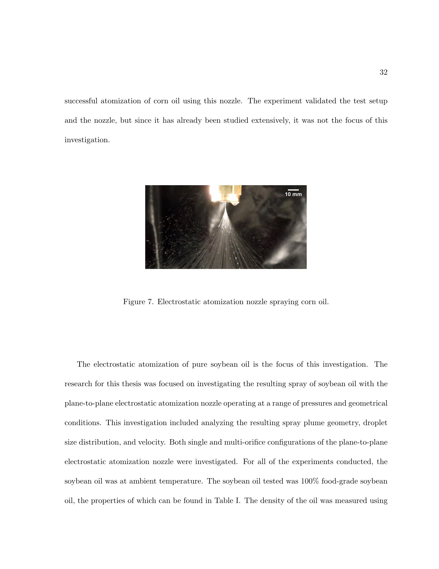
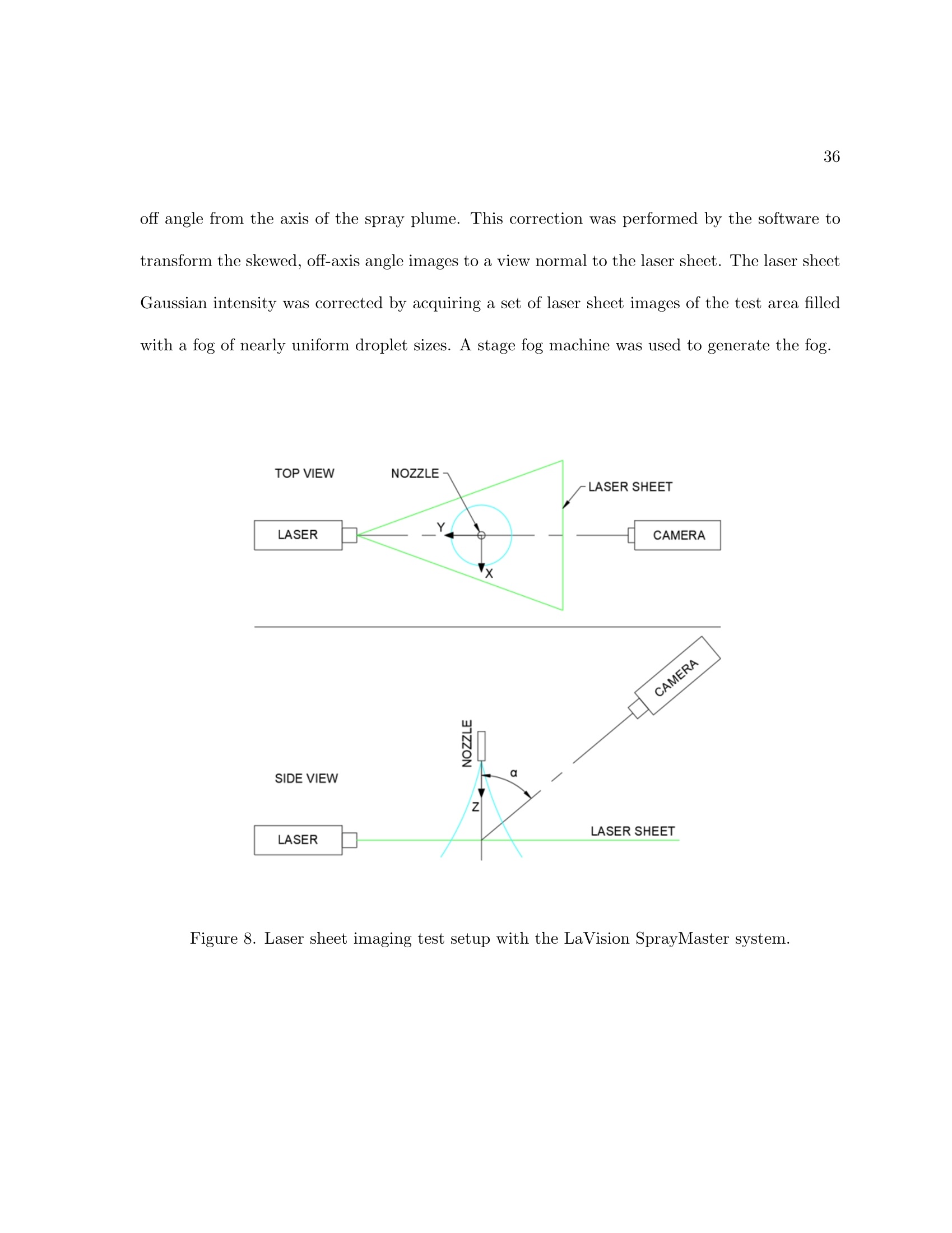
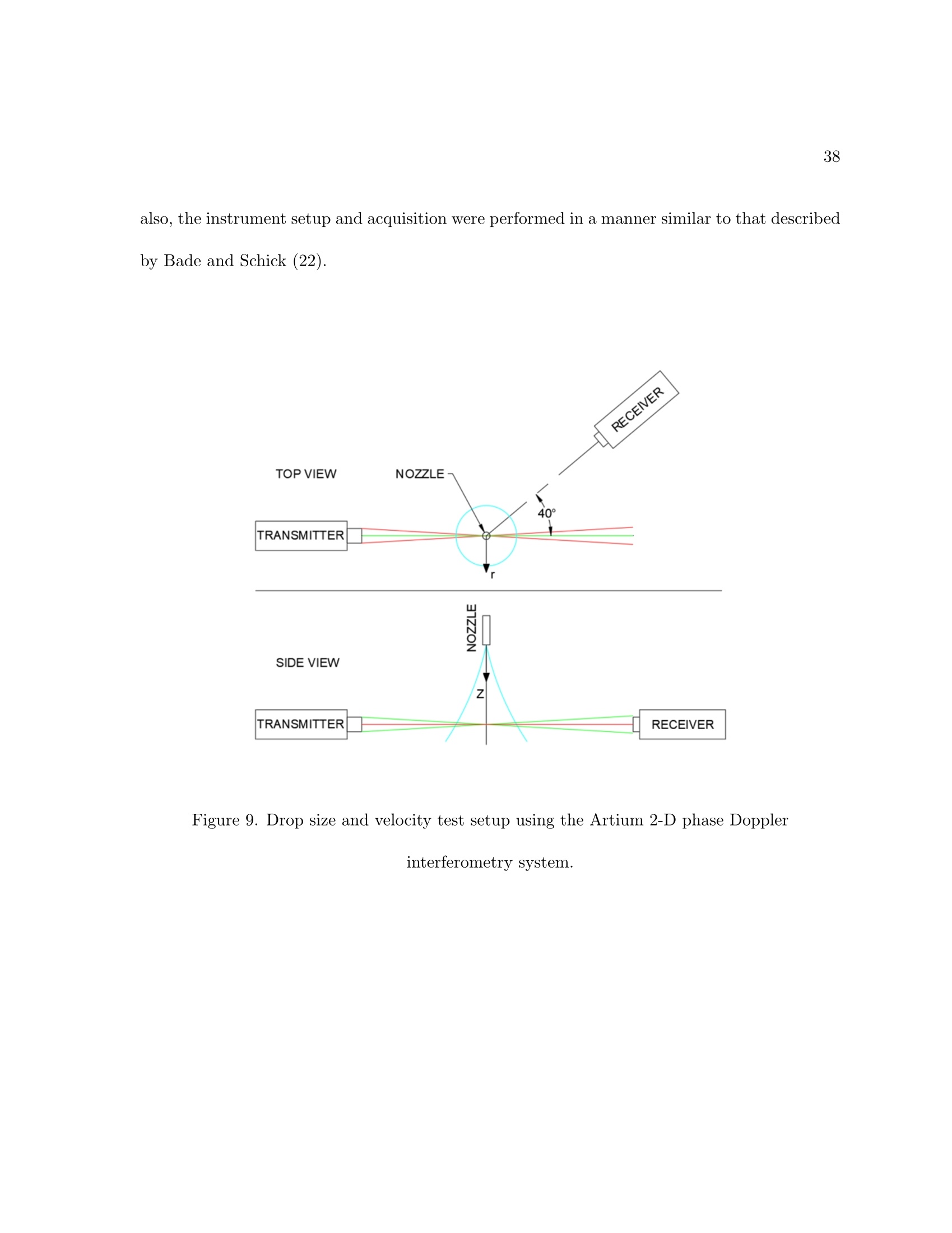
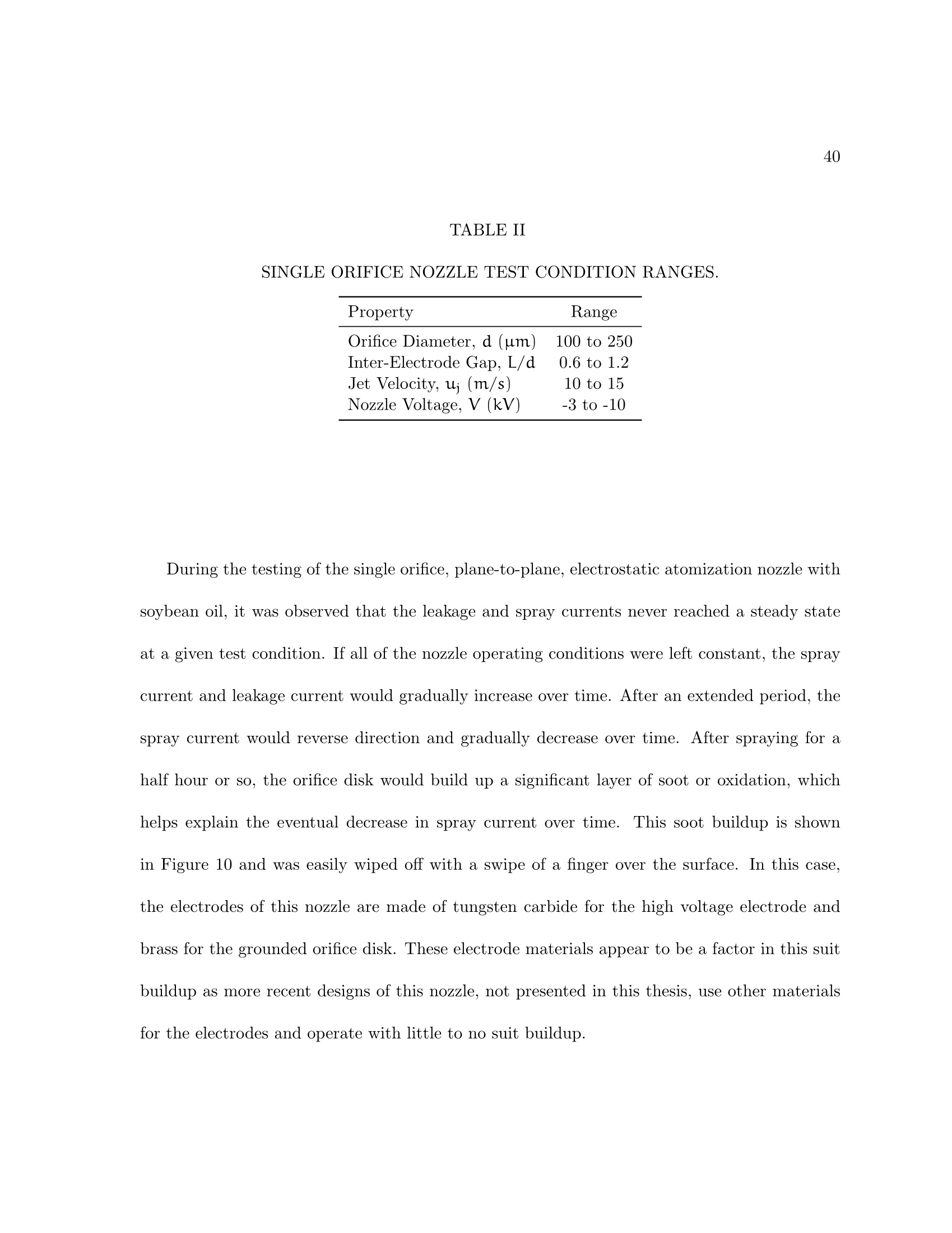
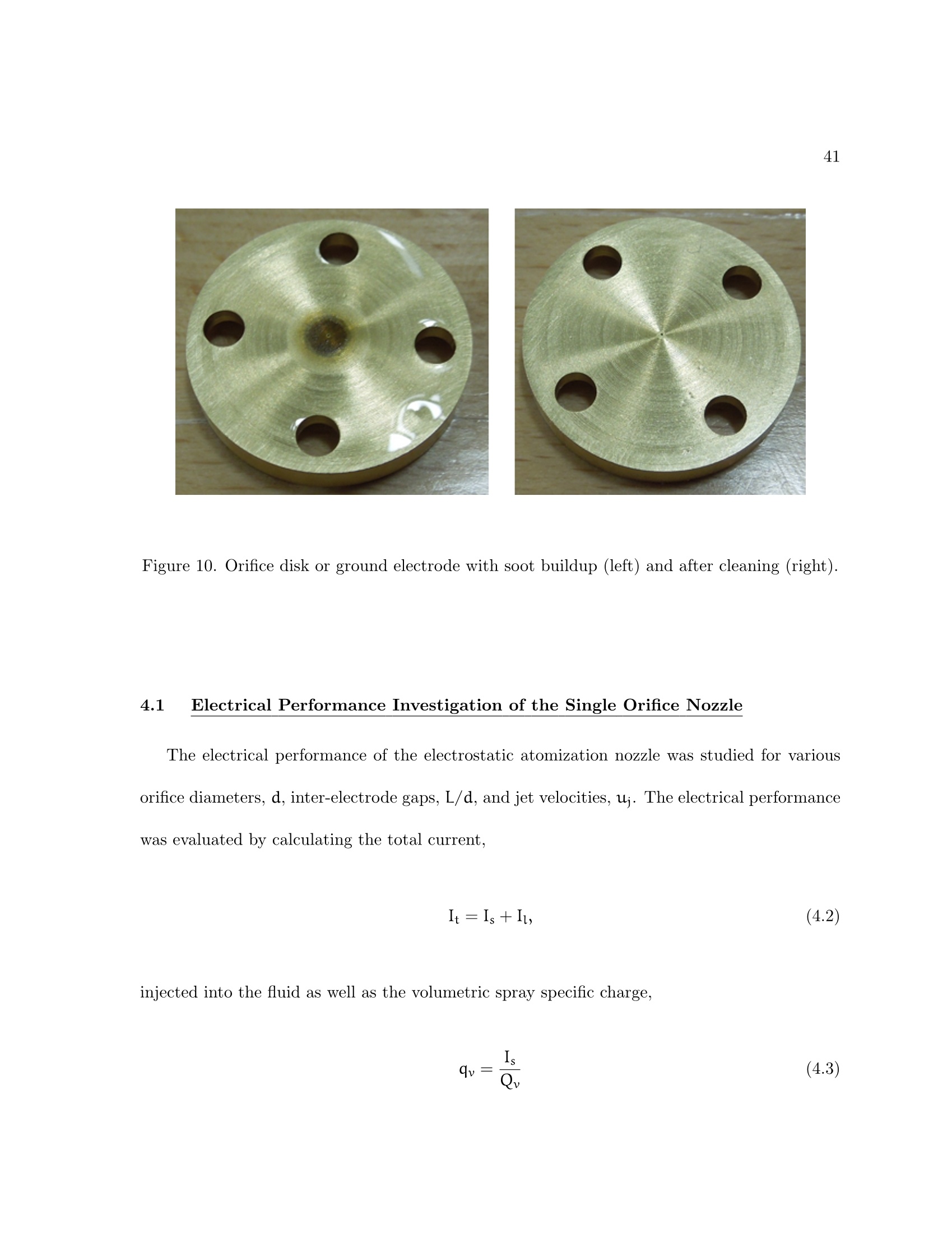
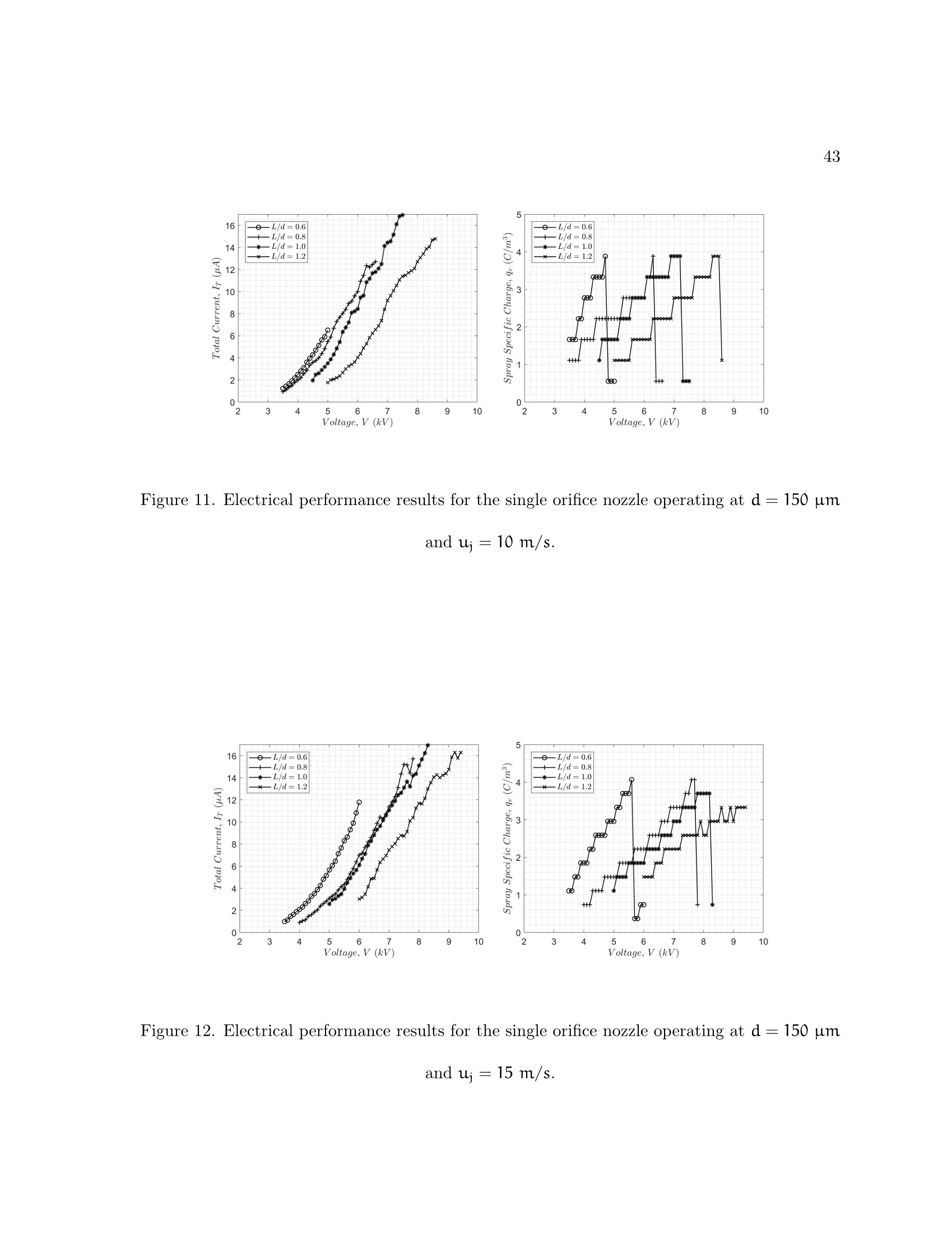
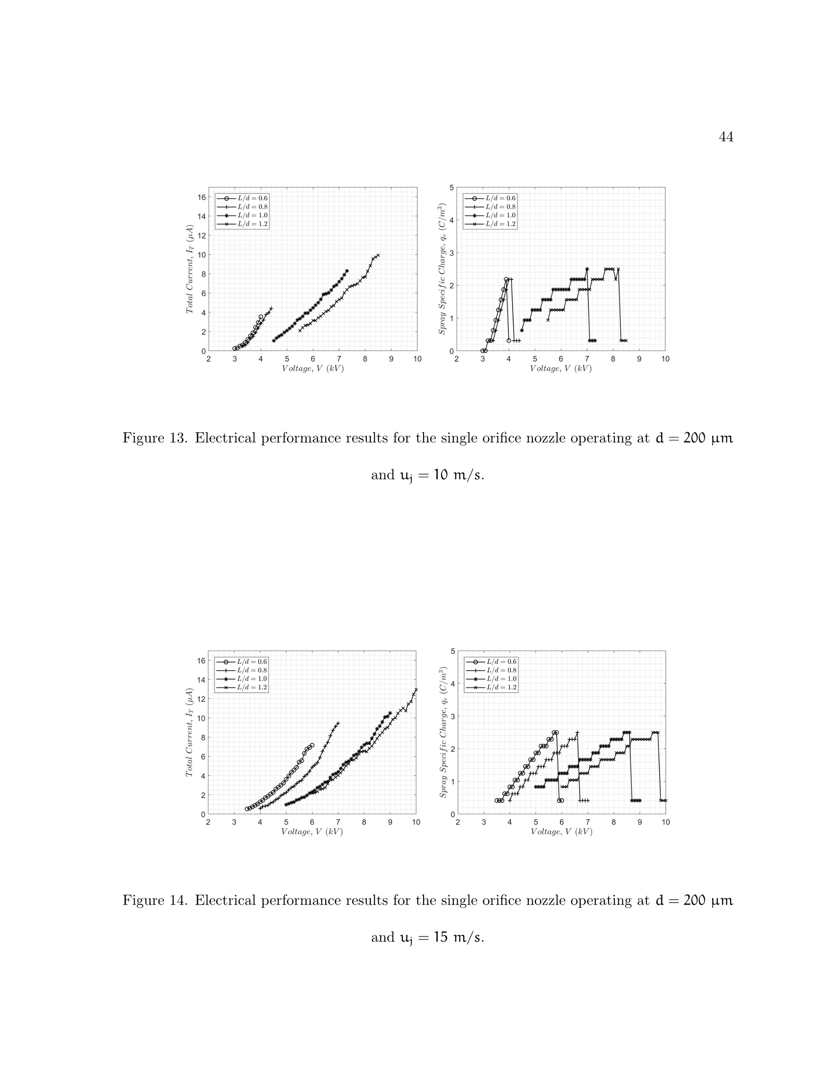
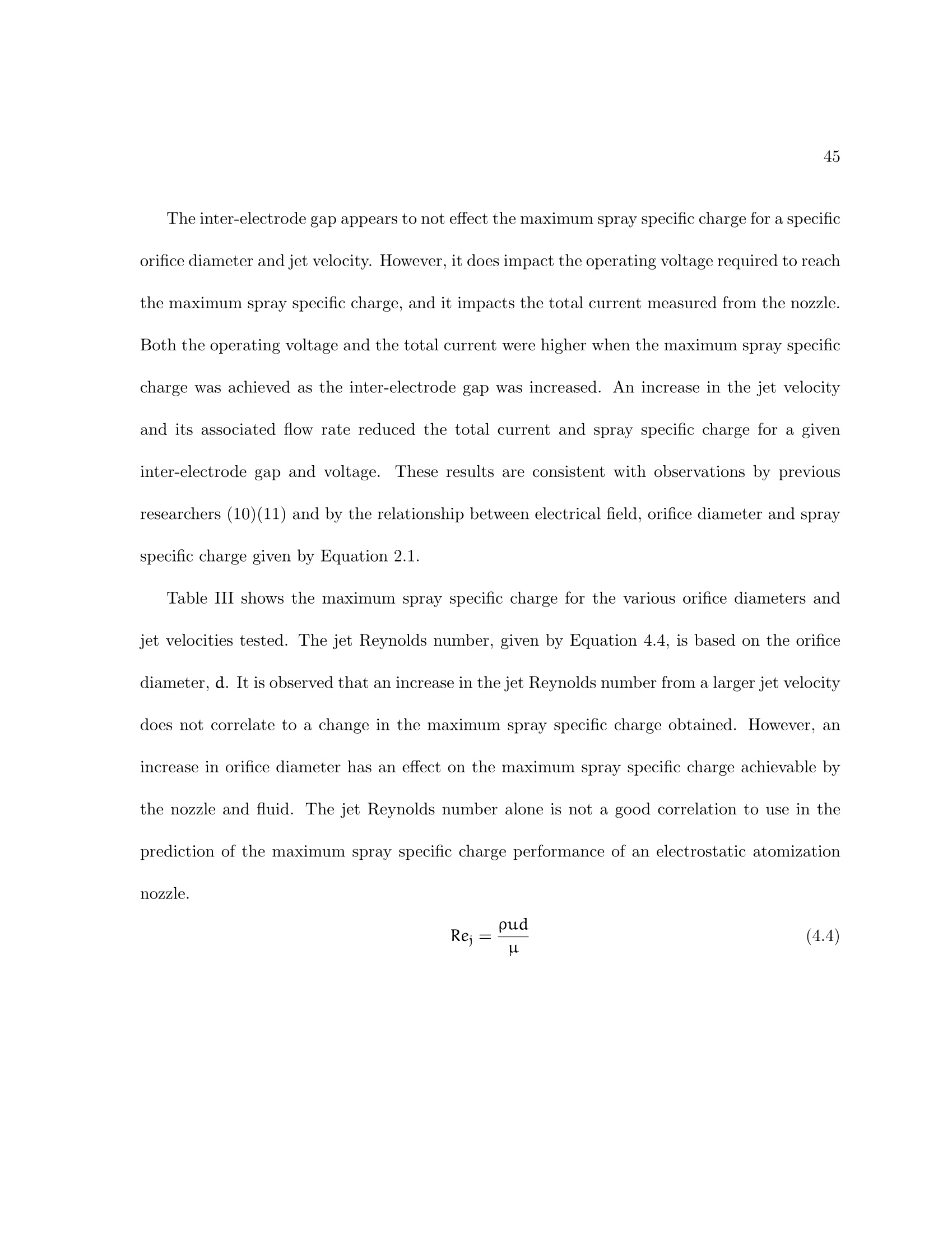
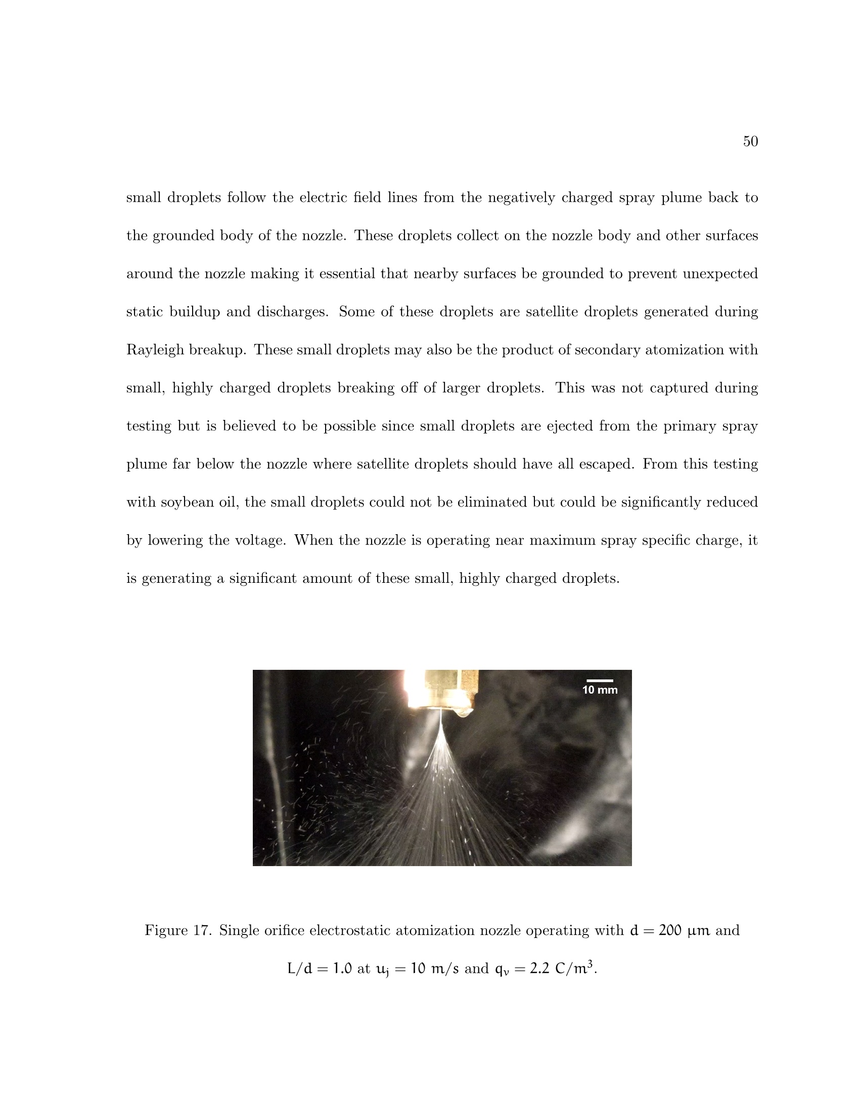
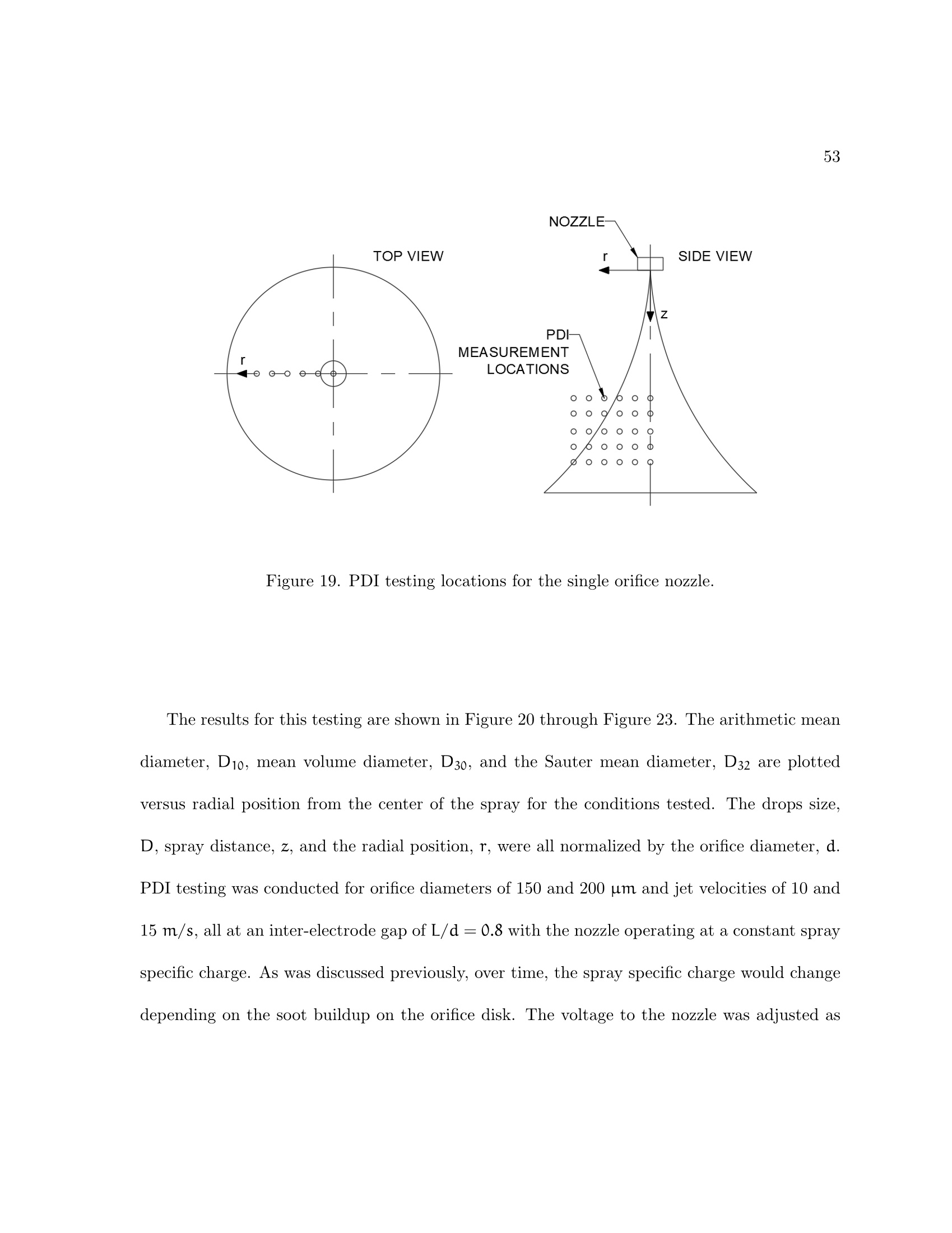
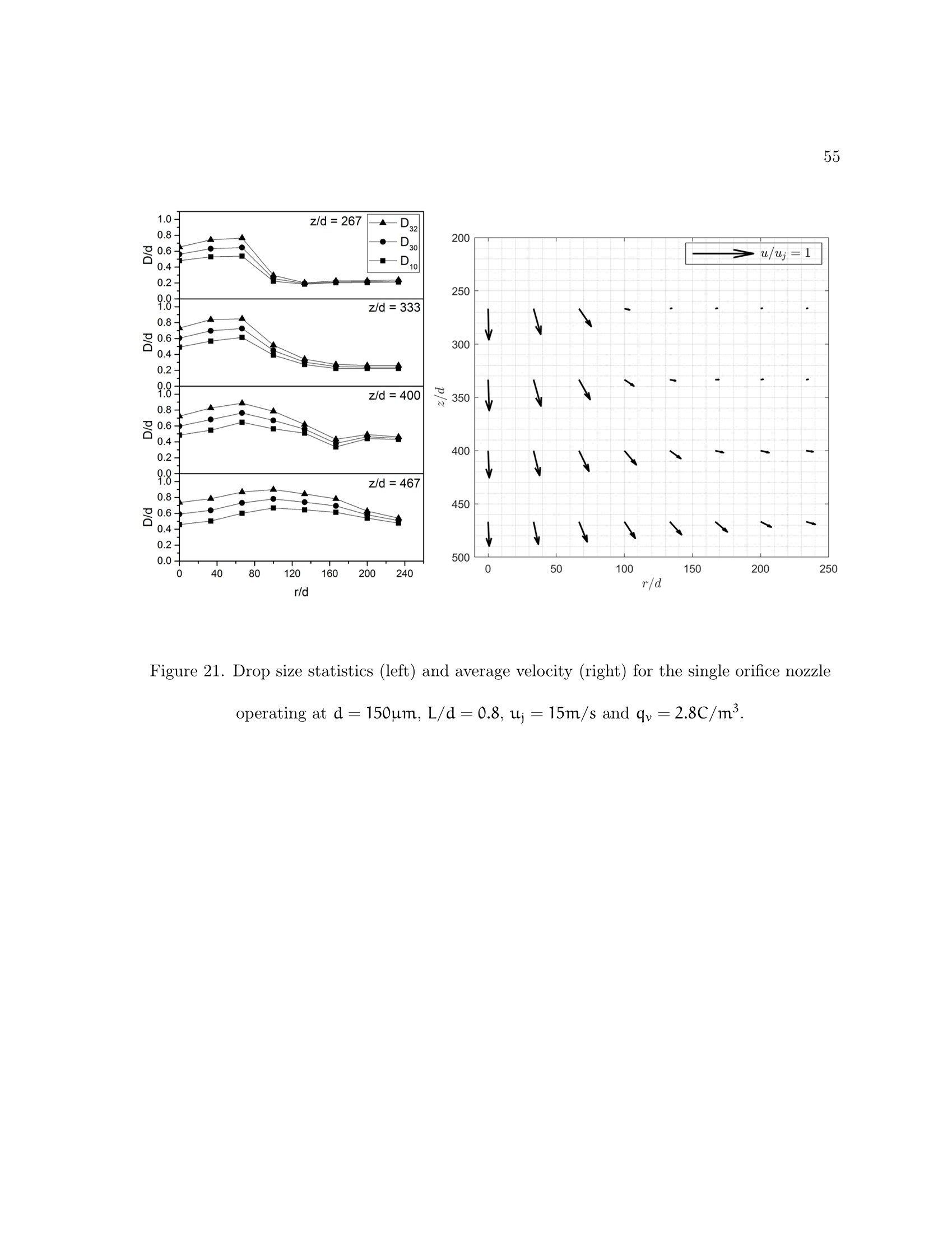
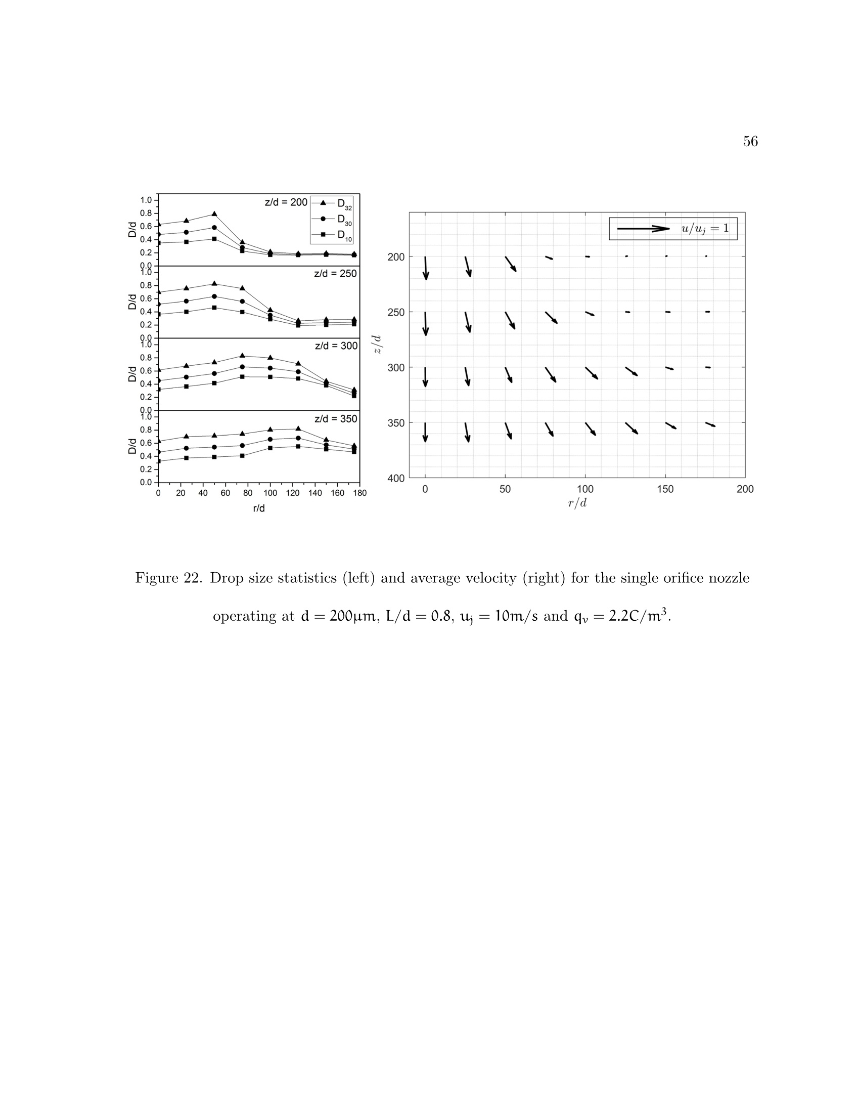
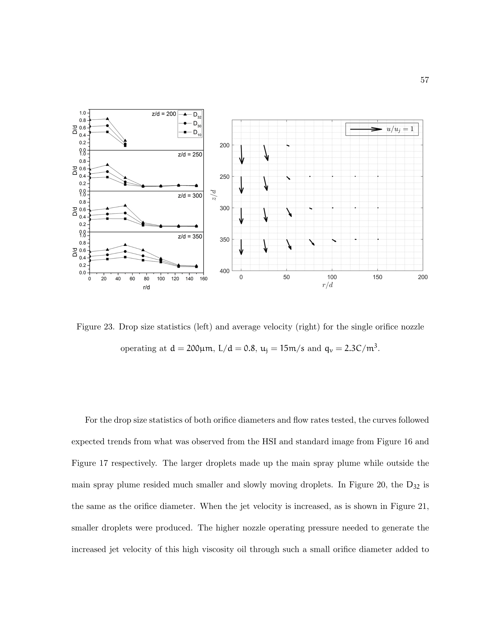
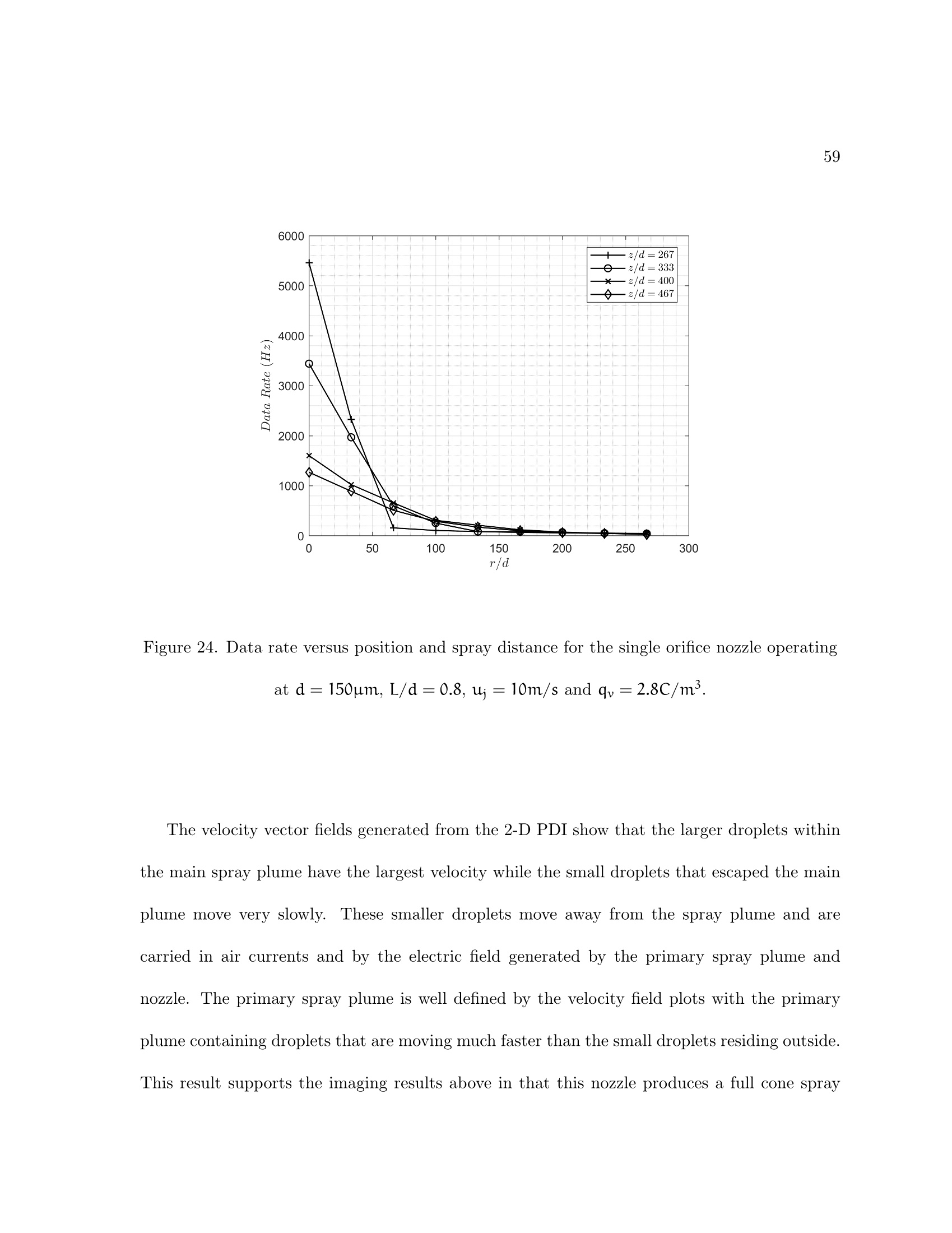
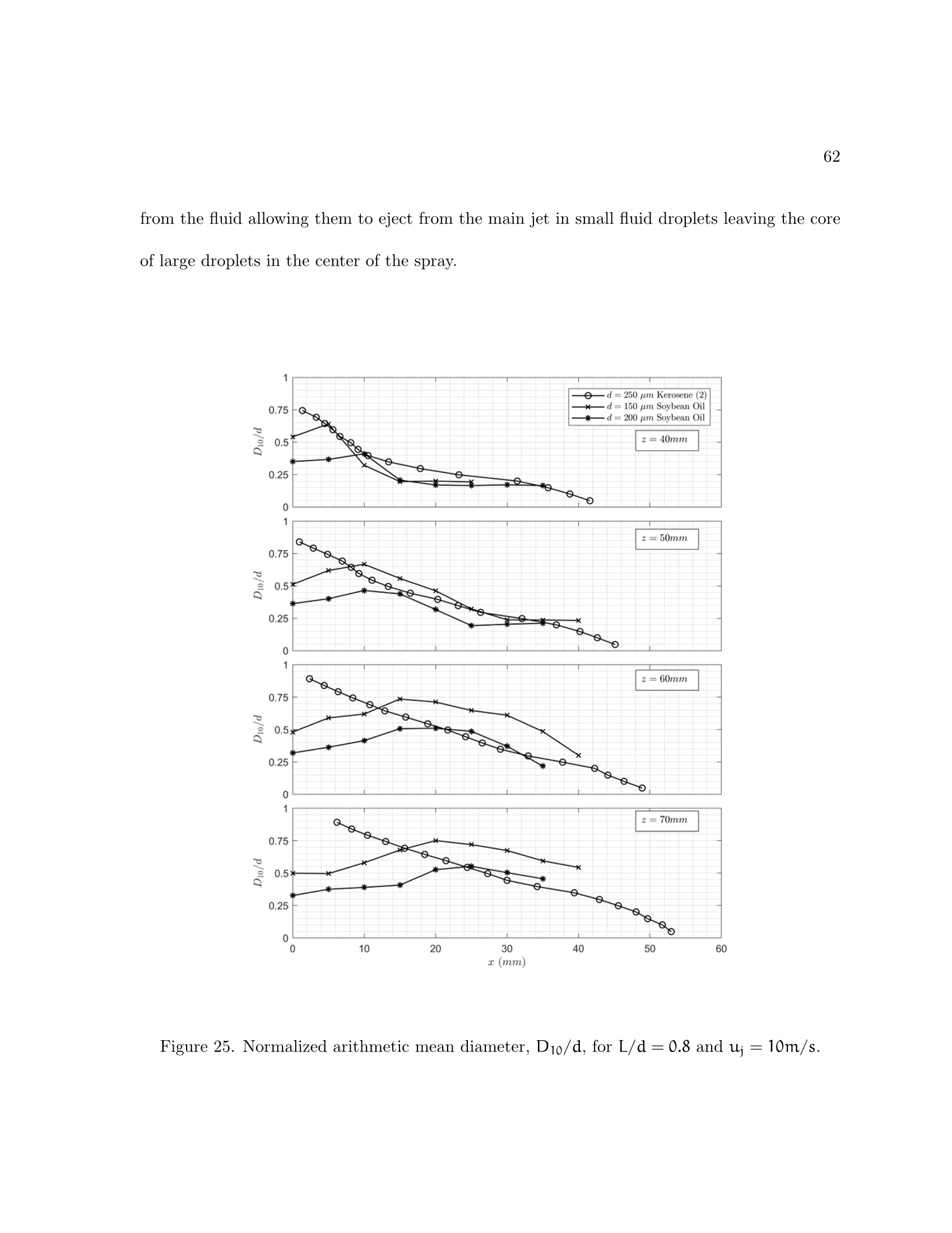
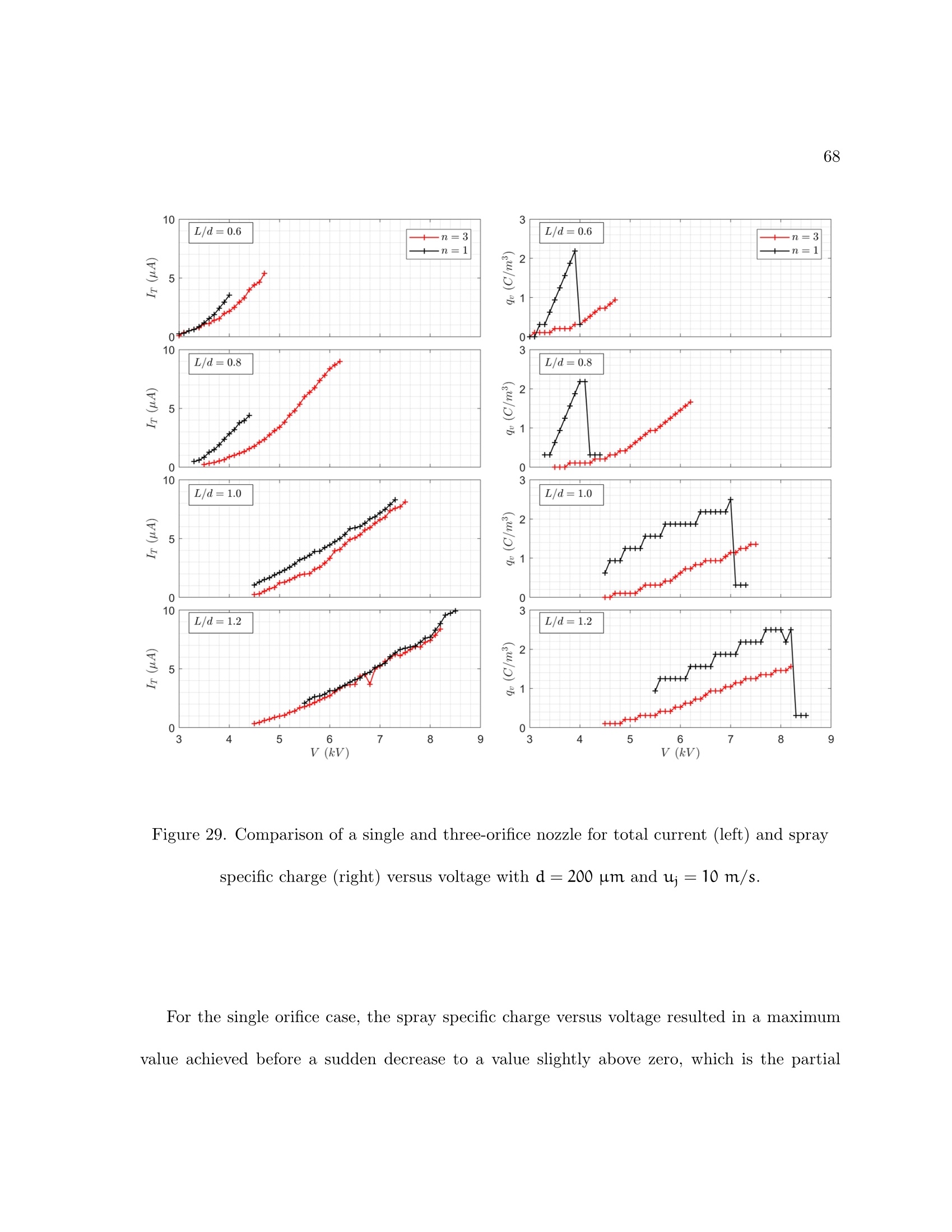
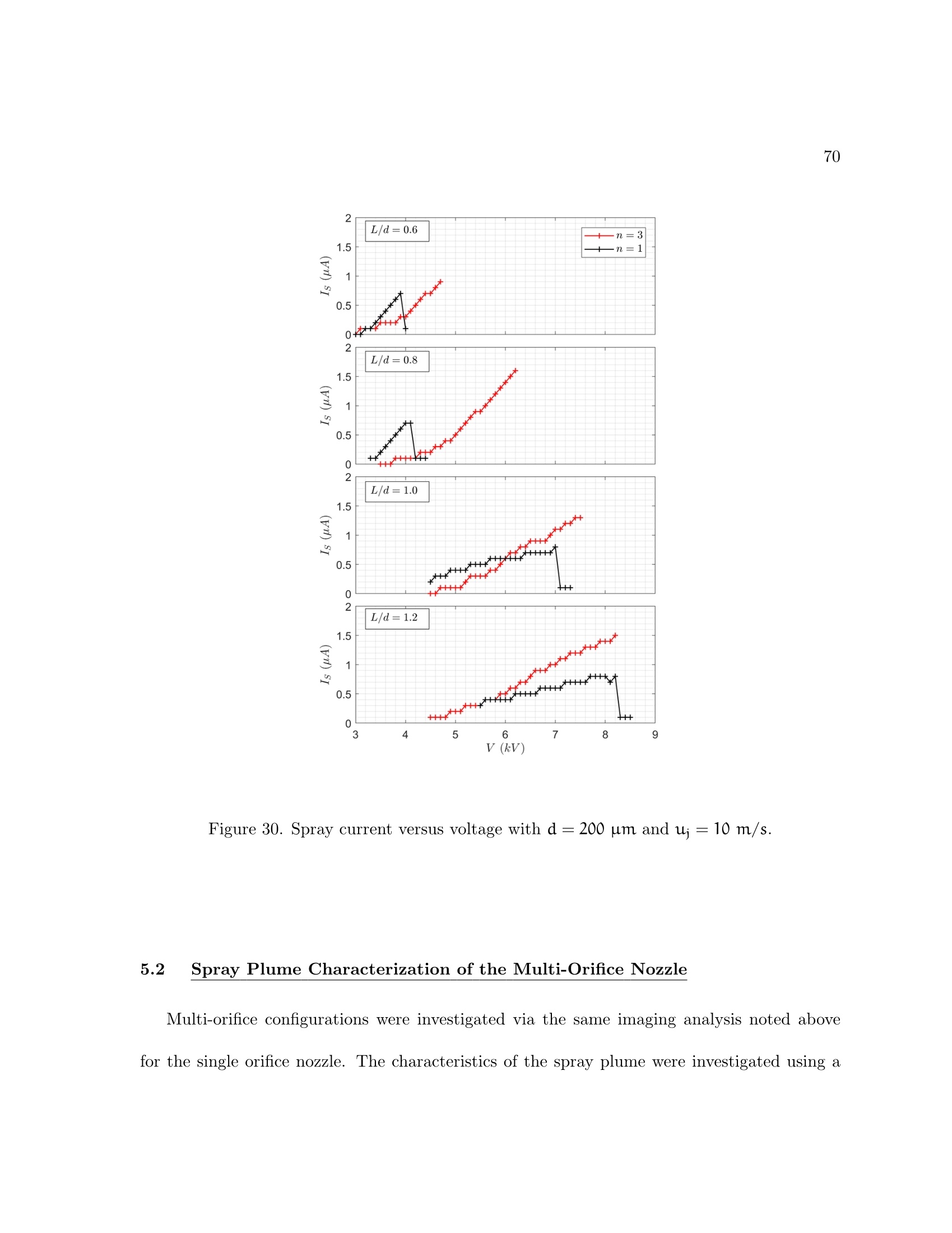
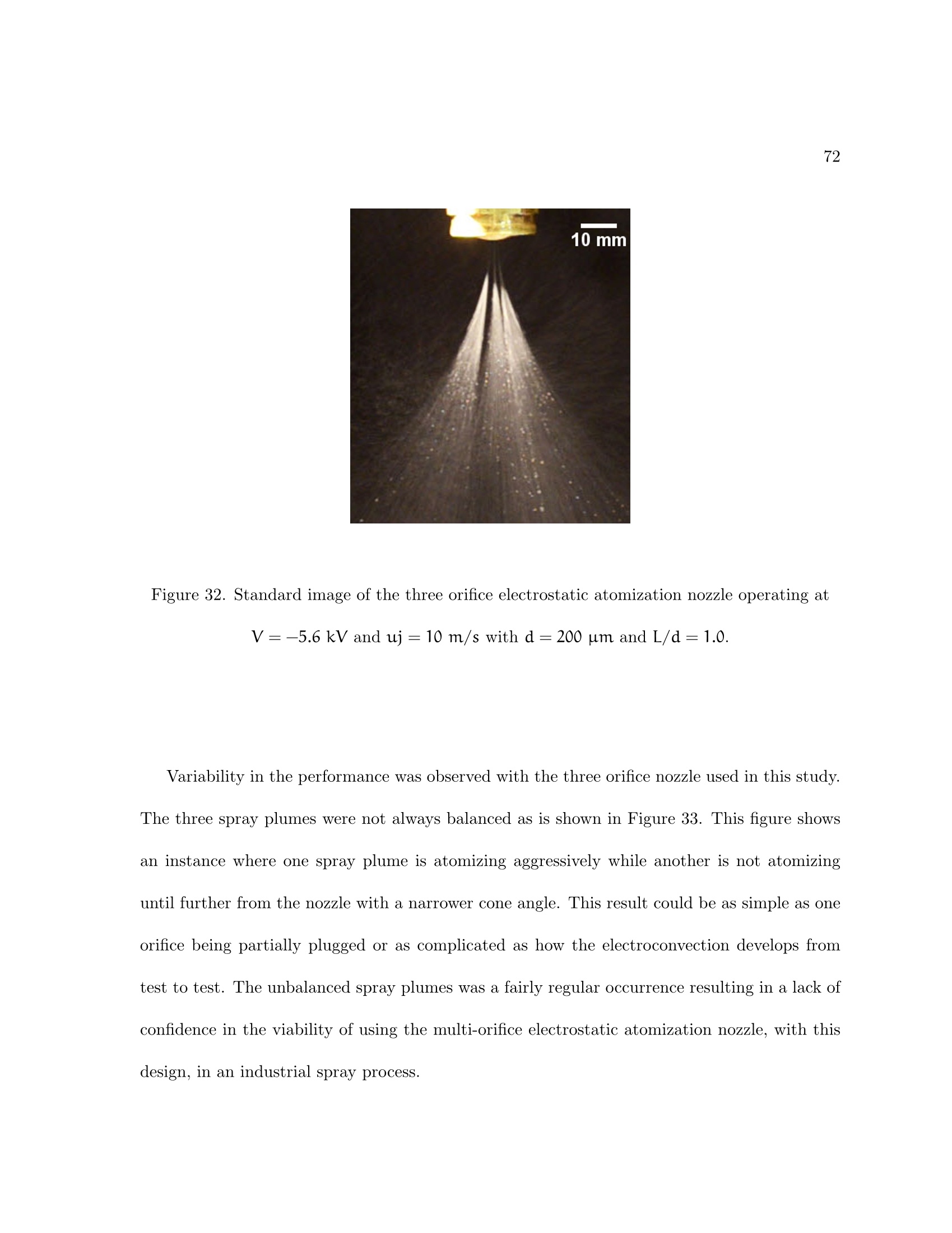
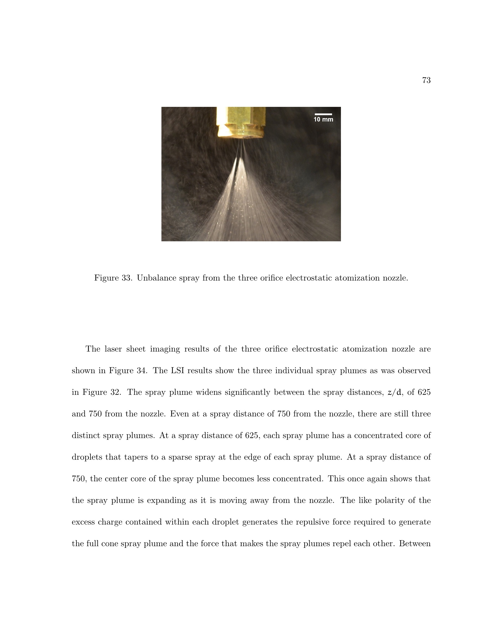
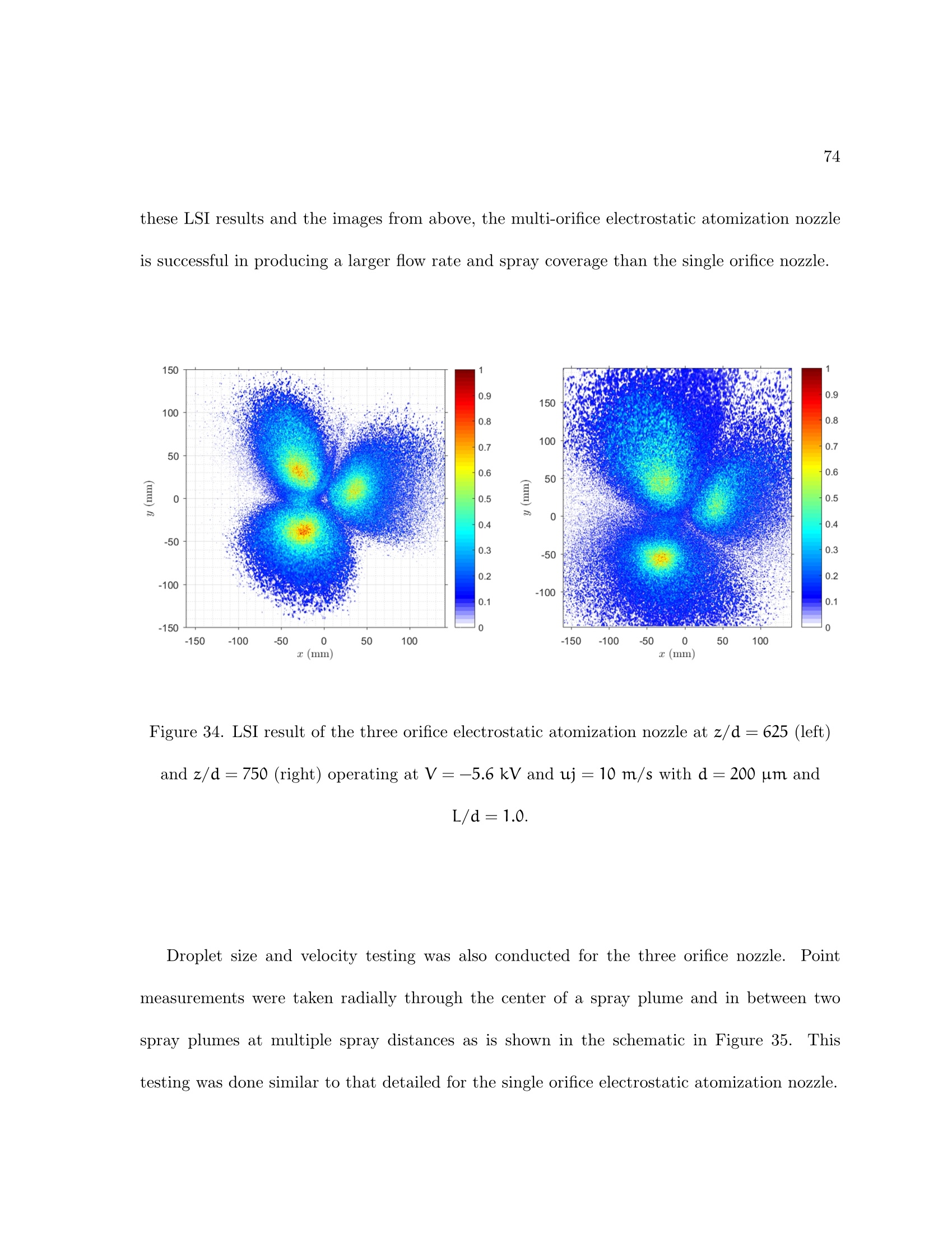
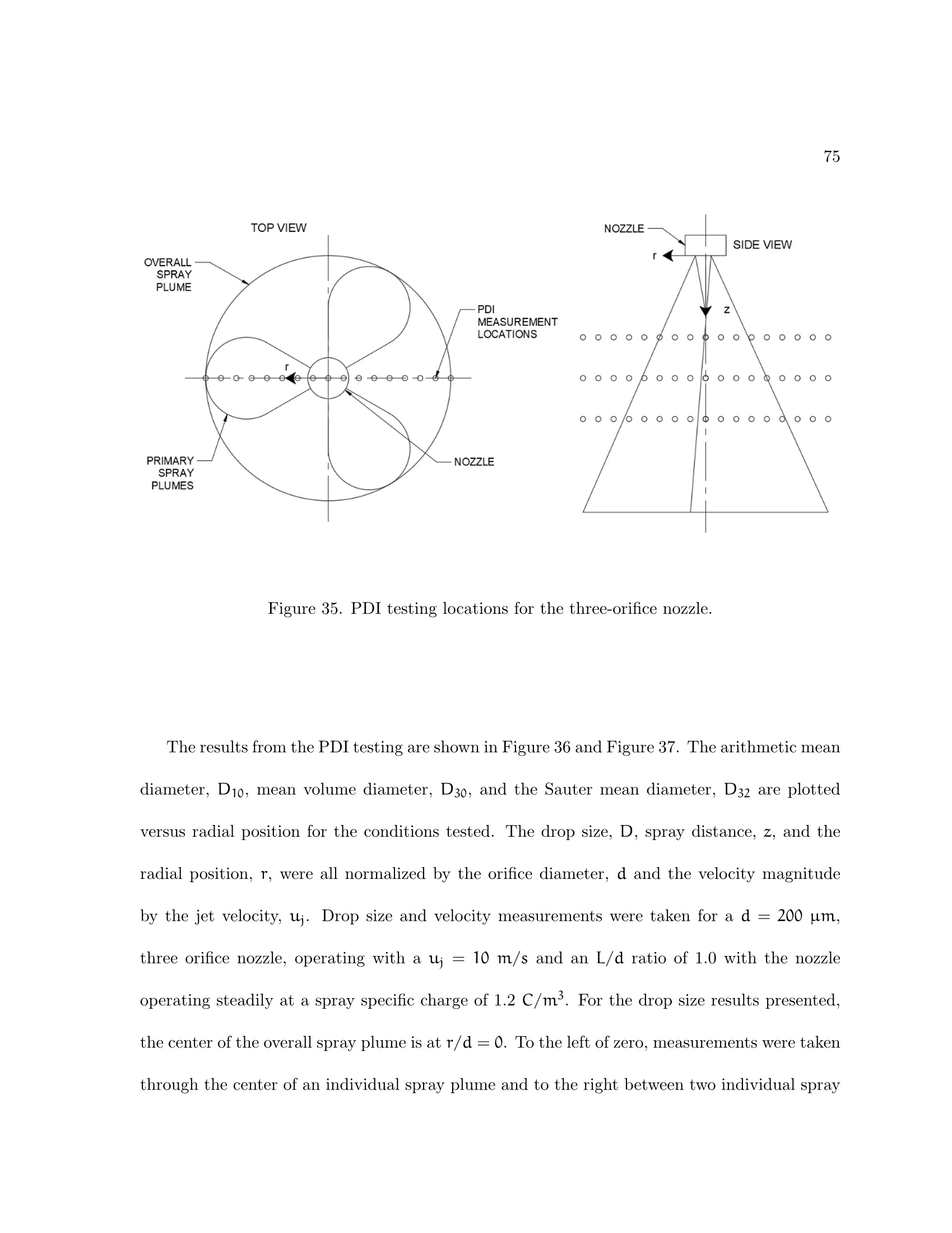
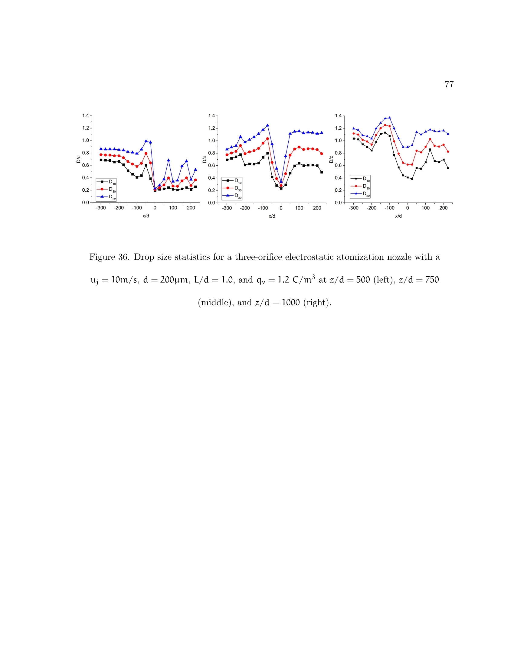
2 3 Electrostatic Atomization of Vegetable Oils with Single and Multi-Orifice Nozzles by PAUL WILLIAM VESELY B.S., University of Illinois at Chicago, 2013 Thesis submitted in partial fulfillment of the requirements for the degree of Master of Science in Mechanical Engineering in the Graduate College of the University of Illinois at Chicago, 2017 Chicago, Illinois Defense Committee: Farzad Mashayek, Chair and Adviser Alexander Yarin John Shrimpton, University of Southampton, UK, Co-Adviser This thesis is dedicated to my wife, Emilee Johnson, without whom it would never havebeen accomplished. ACKNOWLEDGMENTS I would like to acknowledge and thank Dr. Mashayek and Dr.Shrimpton for being myadvisers throughout my master’s research project and for being on my thesis committee. Addi-tionally, I would like to thank Dr. Yarin for being on my thesis committee. Their unwaveringsupport, assistance, and guidance in all areas of this project helped me accomplish my researchgoals and enjoy myself in the process. I would like to acknowledge Rudolf Schick and SprayingSystems Company for sponsoring my project and for providing the laboratory space, equipment,and resources to perform the research for this thesis. Additionally, I would like to acknowl-edge and thank Rudolf Schick and Spraying Systems Co. for allowing me the opportunity toparticipate in their work-study program while pursuing my master’s degree.. The experiencegained while simultaneously taking graduate courses, conducting research, and adding to mywork experience and skills was immensely beneficial to my development as an engineer and mygraduate education experience. PWV TABLE OF CONTENTS CHAPTER PAGE INTRODUCTION AND MOTIVATION 2 LITERATURE REVIEW 4 2.1 Previous Work 4 2.2 Theoretical Review . 2.2.1 Permittivity.. 8 2.2.2 The Coulomb Force and Gauss's Law . 8 2.2.3 Dielectrics and Polarization.. 9 2.2.4 Electroquasistatic Assumptions 10 2.2.5 Mobility and Charge Transport...... ....... 11 2.2.6 Conservation of Mass and Momentum 13 2.2.7 Electrical Timescales. 14 2.2.8 Conservation of Momentum in the Non-Dimensional Form.. 16 2.2.9 Important Non-Dimensional Parameters 18 3 EXPERIMENTAL SETUP.. ............... 23 3.1 Electrostatic Atomization Nozzle 24 3.2 Electrical Circuits and Equipment.. 26 Fluid Circuit and Equipment . 29 Oils Tested.. .. 30 Spray Characterization Equipment 34 3.5.1 Standard and High Speed Imaging 34 3.5.2 Laser Sheet Imaging .. 35 3.5.3 Phase Doppler Interferometry 37 4 SINGLE ORIFICE ELECTROSTATIC ATOMIZATION NOZ-ZLE TESTING WITH SOYBEAN OIL 4.1 Electrical Performance Investigation of the Single Orifice Nozzle4.2 Spray Plume Characterization of the Single Orifice Nozzle.. 5 MULTI-ORIFICE ELECTROSTATIC ATOMIZATIONNOZZLETESTING WITH SOYBEAN OIL. . 5.1 Electrical Performance Analysis of the Multi-Orifice Nozzle 5.2 Spray Plume Characterization of the Multi-Orifice Nozzle.. 6 CONCLUSIONS AND FUTURE WORK.. 6.1 Conclusions TABLE OF CONTENTS (Continued) CHAPTER P A G E 6.2 Recommendations for Future Work 82 CITED LITERATURE 83 VITA. 85 LIST OF TABLES TABLE PAGE PROPERTIES OF SOYBEAN OIL 33 II SINGLE ORIFICE NOZZLE TEST CONDITION RANGES. . 40 III MAXIMUM SPRAY SPECIFIC CHARGE RESULTS FOR THESINGLE ORIFICE NOZZLE ARRANGEMENTS TESTED. 46 IV PROPERTIES COMPARISON OF SOYBEAN OIL AND KEROSENE. 61 LIST OF FIGURES FIGURE PAGE 1 Schematic of the nozzle operation portion of the experimental setup... 24 2 The electrostatic atomization nozzle. . 25 3 Section view of the electrostatic atomization nozzle showing the criticalfeatures of the inter-electrode gap, orifice, and removable orifice disks. . 26 4 Acopian N030HP1 high voltage power source (top) with a custom builtremote control panel (bottom). 27 5 Rotameter calibration curve for soybean oil. 30 6 Electrostatic atomization nozzle spraying white mineral oil. 31 7 Electrostatic atomization nozzle spraying corn oil. . 32 8 Laser sheet imaging test setup with the LaVision SprayMaster system. 36 9 Drop size and velocity test setup using the Artium 2-D phase Dopplerinterferometry system... 38 10 Orifice disk or ground electrode with soot buildup (left) and after clean-ing (right).. 41 11 Electrical performance results for the single orifice nozzle operating atd=150 um anduj=10 m/s.. 43 12 Electrical performance results for the single orifice nozzle operating atd=150 um and uj=15 m/s. .. 43 13 Electrical performance results for the single orifice nozzle operating atd=200 um and uj=10 m/s. 44 14 Electrical performance results for the single orifice nozzle operating atd=200 um and uj=15m/s... 44 LIST OF FIGURES (Continued) FIGURE PAGE 15 Electrical performance results comparison of the plane-to-plane (PL-2-PL) nozzle to the point-to-plane (PT-2-PL) results from Malkawi for thesingle orifice nozzle operating at L/d=1.0 and uj=15 m/s. 47 16 High speed imaging of the single orifice nozzle with d=150um andL/d =0.8 operating at uj = 10m/s and qv =2.2C/m’ recorded at5,000 fps. 49 17 Single orifice electrostatic atomization nozzle operating with d=200um and L/d =1.0 at uj=10 m/s and qv=2.2 C/m. 50 18 LSI results for the single orifice nozzle with d=200um and L/d=0.8while operating at uj =10m/s and qv=1.2C/m’ at various distances(left) and at z= 40 mm (right) from the nozzle... 52 19 PDI testing locations for the single orifice nozzle. 53 20 Drop size statistics (left) and average velocity (right) for the single orificenozzle operating at d=150um, L/d=0.8,uj=10m/s and qv=2.8C/m’. 54 21 Drop size statistics (left) and average velocity (right) for the single orificenozzle operating at d=150um,L/d=0.8, uj= 15m/s and qv=2.8C/m. 55 22 Drop size statistics (left) and average velocity (right) for the single orificenozzle operating at d=200um, L/d=0.8,uj=10m/s and qv=2.2C/m'. 56 23 Drop size statistics (left) and average velocity (right) for the single orificenozzle operating at d=200um,L/d=0.8, uj= 15m/s and qv=2.3C/m. 57 24 Data rate versus position and spray distance for the single orifice nozzleoperating at d=150um, L/d=0.8,u;=10m/s and qv=2.8C/m. 59 25 Normalized arithmetic mean diameter, D10/d, for L/d=0.8 and uj=10m/s.. 62 26 A schematic of the intended three orifice configuration (left) and theactual three orifice configuration produced and tested (right).. 64 27 Three orifice configuration with orifices located within the outer diame-ter of the high voltage electrode. 65 28 Orifice plate with pitting due to arcing between the electrodes. 66 ix LIST OF FIGURES (Continued) FIGURE PAGE 29 Comparison of a single and three-orifice nozzle for total current (left)and spray specific charge (right) versus voltage with d=200 um anduj=10 m/s. 68 30 Spray current versus voltage with d=200 um and uj=10 m/s. . 70 31 High speed image of the three orifice nozzle operating with no voltage(left), V=-5.6 kV (right) and uj =10 m/s with d=200 um andL/d=1.0... 71 32 Standard image of the three orifice electrostatic atomization nozzle op-erating at V=-5.6 kV and uj =10 m/s with d=200 um and L/d=1.0. 72 33 Unbalance spray from the three orifice electrostatic atomization nozzle. 73 34 LSI result of the three orifice electrostatic atomization nozzle at z/d=625 (left) and z/d=750 (right) operating at V= -5.6 kV and uj=10m/s with d=200 um and L/d=1.0. 74 35 PDI testing locations for the three-orifice nozzle... 75 36 Drop size statistics for a three-orifice electrostatic atomization nozzlewith a uj= 10m/s, d=200um, L/d= 1.0, and qv =1.2 C/m’ atz/d=500 (left), z/d=750 (middle), and z/d= 1000 (right). 77 37 Normalized 2-D velocity (u/u;) profile for a three-orifice electrostaticatomization nozzle with a uj= 10m/s, d= 200um, L/d = 1.0, andqv=1.2C/m.. 78 LIST OF ABBREVIATIONS B[TMagnetic Fieldc =2.998×10°[m/s]Speed of Light in a VacuumDa[m²/s]Ionic Diffusion CoefficientDv[um]Volume DiameterdmOrifice DiameterEV/m]Electric Fielde =1.602×10⁻¹⁹CElementary ChargefINForceg=9.81[m/s]GravityACurrentUnit Vector[A/m²]Current Fluxkb=1.3806× 10⁻²³[m²kg/sK]Boltzmann ConstantLmInter-Electrode Gap Length1mlLength[1/m²]Number DensityPPalPressure[C/kg]Mass Charge DensityQv[m³/s]Volumetric Flow Rate LIST OF ABBREVIATIONS (Continued) q c Electric Charge gv [C/m'] Space Charge or Spray Specific Charge K Temperature t ls Time [m/s] Velocity [J/m3] Energy Density Voltage x, y, z, t mml Position Greek [1/K] Thermal Expansion Coefficient [F/m] Permittivity 8o=8.854×10⁻¹² [F/m] Permittivity of Free Space Er Relative Permittivity n Atomizer Efficiency [m²/Vs] Ion Mobility Xa m Debye LengthDynamic Viscosity um [H/m Permeability St Kinematic Viscosity 八=3.1416 Ratio of the Circumference to the Diameter of a Circle LIST OF ABBREVIATIONS (Continued) [kg/m'] Densitys Timescale Constant Dimensionless Parameters CInjection Strength ParameterFrFroude NumberGrGrashof NumberMMobility ParameterRaRayleigh NumberReReynolds NumberElectric Rayleigh Parameter Acronyms EHDelectrohydrodynamicHSIhigh-speed imagingHVPShigh voltage power sourceLSIlaser sheet imagingPDIphase Doppler interferometry SUMMARY An electrostatic atomization nozzle was investigated to determine the viability of using thistechnology with soybean oil for industrial oil coating processes.The nozzle was constructedwith a blunt high voltage electrode producing a plane-to-plane electrostatic atomization noz-zle. Testing was conducted for various nozzle geometries including multiple inter-electrode gapdistances, orifice diameters, and number of orifices. These nozzle variations were tested at twoflow rates (jet velocities) for electrical performance and spray plume characterization. The mo-tivation for testing a multi-orifice version of this nozzle was to increase the oil throughput forthe nozzle and spray coverage. The increased capacity of the multi-orifice nozzle would providemore opportunity for the electrostatic atomization system to replace other nozzle technologycurrently in place for oil coating processes. It was found that this nozzle design works well for the single orifice configuration withsoybean oil. The single orifice nozzle produced spray specific charge results similar to previousresearch with soybean oil. This nozzle with soybean oil also produced similar drop size statisticscompared to previous research with kerosene and diesel oil, which have much lower viscosity thansoybean oil. This suggests that atomization mechanism of bending and Rayleigh instability isindependent of the viscosity of the oil as far as the resulting drop size distribution is concerned. The multi-orifice designs of the electrostatic atomization nozzle proved to be challenging andnot consistent. Unexpected arcing occurred in the triangular region between the three orifices.Even with all three of the orifices residing well within the outer diameter of the high voltage SUMMARY (Continued) electrode, balanced charging did not always occur between the three oil jets resulting in narrowspray plumes among wide vigorously atomized spray plumes.However, it was successfullyoperated and met the goals of increasing the flow rate and spray coverage produced by thenozzle. Some further design refinements could alleviate the challenges encountered with thisnozzle during this investigation. CHAPTER 1 INTRODUCTION AND MOTIVATION Electrostatic atomization nozzles have been studied by many researchers in the past decades.Electrohydrodynamics is an attractive method to atomize dielectric fluids with high viscosity,like oils. Traditionally, these are atomized via high hydraulic pressure or with the assistanceof a compressed atomization gas. Both methods can generate small droplets but with the highenergy cost associated with pumping or compressing the liquid and atomization gas, respec-tively. Heating of the oil before spraying is a typical process in industry to reduce the viscosityof the fluids to produce smaller droplets with lower atomization pressures or to improve spraypattern quality. Electrohydrodynamic atomization can generate finely atomized droplets withonly milliwatts ofelectrical power consumption, with the added benefit of the charged dropletsseeking for and collecting onto electrically grounded targets resulting in a very high transferefficiency.Poor transfer efficiency is a common problem is traditional industrial oil coatingprocesses. The motivation for the work detailed in this thesis is to develop an electrostatic atomizationnozzle for industrial oil coating processes. Industrial oil coating processes would greatly benefitfrom charged, targeted sprays resulting in high transfer efficiency. The nozzle requires furtherdevelopment and testing to increase flow rate, spray coverage, and reliability to work for anindustrial process at the conveyor speeds currently being used for oil coating applications. The majority of work conducted by previous researchers was related to electrostaticallyatomizing fuels for combustion processes. For this thesis, the work focused on studying howtechnology designed for spraying low viscosity fuels like diesel and jet fuels works with higherviscosity vegetable oils building on the research started by Malkawi (formerly Al-Ahmad) (1).Malkawi investigated the electrical performance of the electrostatic atomization nozzle withvarious electrode designs with the hydrocarbon-based fuels of diesel and JP8 and with thevegetable oils of corn and soybean oil. Malkawi also investigated the electrical performance ofmulti-orifice configurations of the electrostatic atomization nozzle with various electrode shapeswith diesel fuel only. For this thesis, experiments were conducted on single and multi-orifice electrostatic atom-ization nozzles spraying soybean oil. The electrical performance of these nozzles was testedand compared to Malkawi’s results to validate the nozzle used and the experimental setups.New contributions to the study of electrostatic atomization nozzles consisted of characteriz-ing the spray plume generated by the single and multi-orifice electrostatic atomization nozzlespraying soybean oil via various imaging techniques including high-speed imaging, laser sheetimaging, and phase Doppler interferometry. Drop size distribution results for the single orificeelectrostatic atomization nozzle were compared to results for kerosene conducted by Shrimptonand Yule (2). Various nozzle geometries including the inter-electrode gap, orifice diameter, andnumber of orifices were investigated to see how they impact the spray plume generated by thenozzle. The structure of the thesis begins with a literature and theoretical review, followed by the presentation of the various experimental setups used, followed by experimental results andanalysis, and ending with the conclusions and recommended future work. CHAPTER 2 LITERATURE REVIEW 2.1 Previous Work Electrohydrodynamics is the study of how electric fields impact fluid motion.Some othe earlier work on this phenomenon was conducted by Melcher and Taylor (3). TThey didan experiment that demonstrated that electroconvection could be induced in corn oil withselective positioningof the high voltage and ground electrodes.The development of EHDnozzles began with Kim and Turnbull (4) who used a needle electrode in a capillary glass tubeto electrostatically spray Freon 113. This nozzle design generated spray currents on the orderof nanoamps and droplets on the order of 10 microns at very low flow rates.A nozzle forelectrospraying uses only one electrode within the nozzle and the spray target is the groundelectrode.Testing of the electrospraying nozzle continued with Robinson et al.(5).Theysprayed silicone oil with the same style nozzle and showed that more resistive fluids could beatomized with the electrospraying nozzle and verified that atomization occurs at lower voltagesif the high voltage electrode has a negative polarity versus a positive polarity. A spray triode nozzle was developed by Kelly (6)to improve on the single electrode versiondeveloped by Kim and Turnbull (4). The spray triode nozzle contains three electrodes; thehigh voltage electrode in the center of the nozzle, a ground electrode plate with holes in thebottom of the nozzle close to the high voltage electrode, and a ground electrode attached to the outside of the nozzle. This nozzle design brought the high voltage and ground electrodesclose together to generate stronger charging of the oil and allowed for the nozzle to operate athigher flow rates. The body of the nozzle was made of a dielectric material. The third electrodeoutside the body nozzle was grounded and was used to assist in drawing the charged fluid outof the nozzle. The high voltage electrode in this nozzle was a sharp point electrode making apoint-to-plane electrode arrangement. The spray triode nozzle was further improved upon by Yule et al. (7). In this design,the needle high voltage electrode was located within a conducting nozzle body, which madeup the ground electrode. No third electrode was connected to the nozzle. Instead, the targetbeing sprayed was grounded and attracted the charged spray. This nozzle was investigated withvarious hydrocarbon fluids like diesel oil, kerosene, and white spirit. This nozzle contained alarge orifice diameter of 500 microns and had a large inter-electrode gap and orifice length. Itproduced an atomized spray but with low spray specific charge, which was typically under 1C/m. This nozzle became known as the 1st generation atomizer. The 2nd generation electrostatic atomization nozzled designed by Shrimpton and Yule (2)simplified the body of the nozzle to focus on the electric field instead of the fluid flow paththrough the nozzle. This new design allowed for the needle high voltage electrode to be muchcloser to the nozzle body and orifice and smaller orifice diameters were tested. With this nozzledesign, they were able to achieve spray specific charge levels up to 3 C/m’ (8). The 3rd generation electrostatic atomization nozzle designed by Rigit and Shrimpton (9)was very similar to the previous version except it included a PTFE guide to keep the needle high voltage electrode centered with the orifice to maximize the electric field strength at thecharging region of the nozzle. This nozzle was used in subsequent studies with various typesof high voltage electrodes and for multi-orifice testing. This atomizer design was used for thisresearch. The single orifice electrostatic atomization nozzle is limited to the maximum orifice diameterand flow rate it can operate at.When the electric field of the jet of fluid exiting the nozzlereaches a critical value, partial breakdown or supercritical breakdown condition occurs and thenozzle stops atomizing (10). At this condition, the electric field is strong enough to generatecorona discharge in the air surrounding the jet of oil that exits the nozzle (11). The maximumelectric field strength achievable before partial breakdown condition occurs is related to theinverse proportional relationship between the jet diameter and the spray specific charge as Since the orifice diameter has to remain small for the liquid jet exiting the nozzle to carryenough charge to generate atomization, multi-orifice nozzle designs were explored by Malkawi(1). The purpose of this research was to increase the flow rate of oil that could be atomizedvia an electrostatic atomization nozzle. This research studied various high voltage electrodetypes as the point electrode is limited to working with a single orifice. He found that the bluntelectrode making up a plane-to-plane electrostatic atomization nozzle resulted in the highestspray specific charge with multiple orifices arranged in a circular array. Further investigation of the multi-orifice electrostatic atomization nozzle was conducted byKourmatzis et al. (12). The purpose of this testing was to see if high levels of spray specificcharge could be obtained if point or needle electrode was used for each orifice within the multi-orifice nozzle. Instead of trying to align an array of needle electrodes with an array of orifices,they made a diamond-encrusted blunt electrode. This resulted in the maximum spray specificcharge being obtained at lower operating voltages. More recently, the EHD nozzle has been investigated for pulsed sprays by Kourmatzis (13)and for remote charging of the fluid and high pressure sprays by Ergene (14). Neither of theseapplications was explored in this thesis. 2.2 Theoretical Review An electrostatic atomization nozzle was built for the testing in this thesis based on thedesign of the 3rd generation atomizer by Rigit and Shrimpton (9). A blunt electrode was usedin this nozzle in place of the needle electrode in the original design based on the studies byMalkawi (1) showing that the blunt ended electrode produced higher levels of spray specificcharge at lower nozzle operating voltages. With the use of a blunt electrode in this generationof an atomizer, a plane-to-plane electrohydrodynamic environment will be in place between theelectrode and the body of the nozzle. The mathematical and physical model representing thecharging process for a plane-to-plane system will be reviewed in this section. The geometry tobe modeled is the simple case of a dielectric fluid in between two plates. One plate is the highvoltage electrode and the other a grounded collecting plate. The theoretic review will begin with some definitions and equation for electrostatics and then will move into electrohydrodynamicsand the Navier-Stokes equations. Lastly, important non-dimensional parameters will be defined. 2.2.1 Permittivity Permittivity relates to a materials ability to transmit an electric field. It is a function ofthe material’s molecular structure and the degree of freedom of the elecrons (15). The relativepermittivity, er is related by the material permittivity, e, and the permittivity of free space, eo,by The permittivity of free space is the permittivity of a vacuum where all charges are free to acton one another and is used as a reference value when determining relative permittivity. 2.2.2 The Coulomb Force and Gauss's Law The presence of charges in the fluid generates electrical forces and influence the electricfield in the spray. Charged particles are of two basic types, monopoles, and dipoles. Monopolesconsist of a single charge whereas a dipole consists of two equal but opposite charges. Coulomb'sLaw describes the force between two static monopoles,q1 and q2 and is shown as In this equation, xi,1 and xi,2 represent the locations of charges q1 and q2 respectively and it,21is the unit vector from q and q1. This gives the force on q1 from q2. A generalized form ofEquation 2.3 showing the force on a charge from many charges is where The relation of the electric field, Ei, generated by the surrounding charges is called Gauss’sLaw. Gauss’s Law relates the instantaneous electric field to the space charge or charge density,qy at any point in the continuum. The differential form of Gauss’s Law is shown as 2.2.3 Dielectrics and Polarization The electrical nature of a material can be classified into two classes, conductors and di-electrics or insulators. In a conductor, like metals, electrons are free to move about the crystalstructure of the material allowing a flow of charge when an electric field is applied. In an insula-tor, electrons are bound to their atoms or molecules. A perfect insulator would be a medium inwhich no charge would flow meaning that the medium has infinite resistivity. When an electricfield is applied to a dielectric medium, charge carriers are restricted from moving indefinitely due to their bond with their atom or molecule, and instead, the positive charge carriers alignwith the electric field and the negative charge carriers against creating the polarized state. 2.2.4 Electroquasistatic Assumptions The electroquasistatic assumption states that the electrical energy is much greater thanthe magnetic energy resulting in magnetic energy effects being ignored (16). Electrical andmagnetic energy densities are respectively defined by the following: To satisfy the electroquasistatic assumption, the ratio of electrical to magnetic energy densitiesmust be much greater than one, shown as As a result of the electroquasistatic assumption, the general Maxwell equations reduce to thefollowing: 2.2.5 Mobility and Charge Transport Several factors affect the transport of charge in a dielectric liquid medium. The first is thetransport of charge, or current flux, by the convective bulk motion of the liquid (15) shown as In this equation, the velocity, ui, is known as the ionic drift velocity which is defined as and is the terminal velocity ofthe charge in the medium. The ionic mobility, k, in an insulatingfluid is related to the fluid’s viscosity by Walden’s Rule (15) and is shown as where Kn is ionic mobility for negative polarity charging, Kp is for positive polarity charging, andu is the viscosity of the insulating fluid. The ionic mobility is defined as the relationship betweenthe electric field applied and the terminal velocity of a charge (13). Using Equation 2.14, thecurrent flux can be rewritten and be defined as the ionic drift equation given by Charge carriers also travel by diffusion into the dielectric fluid. The Debye length is the thicknessof this diffusion area around an electrode and is defined by where n represents the number density of charge carriers. The current flux due to diffusion isshown as where Da is the ionic diffusion coefficient given by the Einstein relation (15) shown as where T is temperature, k, is the Boltzmann constant and e is the elementary charge. Charge conservation is the principle that electric charge cannot be created or destroyed.Summing the three current flux equations together and using the scalar transport Equation 2.12(15), we get the following: 2.2.6 Conservation of Mass and Momentum The Navier-Stokes equations for mass and momentum of classical fluid mechanics are mod-ified to introduce the effects of the electrical forces on the fluid. The one-dimensional, in-compressible version of the Navier-Stokes equations will be explored for this application ofelectrohydrodynamics. For the conservation of mass, the effect of electrical forces does notresult in the addition of any new terms to the equation used for classical fluid mechanics, andis shown as For the conservation of momentum. a new term, fi, is added to include the effect of the electrical force due to the electrical chargepresent in the fluid. This new term represents the volume electrical force for a linear medium(15), and is shown as The leftmost term is Equation 2.4, Gauss’s Law, and is the most dominant term of the three.The middle term is called the dielectric force and is significant in alternating electric fields witha cycle significantly smaller than the charge relaxation or ionic transit time (16). The right term is the electrostrictive pressure and may be grouped with the standard pressure term inthe conservation of momentum equation. 2.2.7 Electrical Timescales There are many timescales associated with Electrohydrodynamics with many interpretationsdepending on the application.These timescales aid in defining the various processes thatoccur within a electrostatic atomizer. To define these time scales, reference values for lengthlo, velocity uo, charge density qvo, voltage Vo, and electric field E。will be used.With theassumption that the dielectric fluid is incompressible and ignoring temperature effects, thedensity p and viscosity u of the dielectric medium are considered reference values (15). The space charge relaxation timescale is defined by and characterizes the rate which charge decays from a given source (15). With the space chargebeing on the bottom of this ratio, a smaller initial space charge will decay more slowly than alarge one. The ionic diffusion timescale is relevant close to the high voltage electrode where a thinlayer of ion diffusion occurs. In this layer, an electrochemical reaction occurs which produces the charge carriers in the fluid (13). The electrochemical reaction appears to be due to faradicreactions at the electrodes(17). The ionic diffusion timescale is given by The ionic transit timescale is the proportion of the characteristic length of the electrohy-drodynamic process to the drift of ions (15) and is shown as This timescale is of a higher relevance than the ionic diffusion timescale if the bulk flow con-vection is being studied away from the electrode. The electro-viscous timescale compares viscous forces to electrical forces given by This timescale describes how quickly a liquid accelerates to a constant after the voltage isinitially applied to the electrode (15). The electro-inertial timescale compares the inertial forces to the electrical forces. Thistimescale describes the time taken for the fluid to travel the characteristic length due to an electric pressure (13). This timescale is relevant when inertial and electrical forces are of thesame order of magnitude (15). The electro-inertial timescale is given by Two non-electrohydrodynamic timescales are essential to the equations to be discussed inthe next subsection. They are the mechanical and viscous timescales. The mechanical timescalegiven by which relates the reference length to the reference velocity. The viscous timescale, represents the time needed for the velocity gradient to develop within the moving liquid (13). 2.2.8 Conservation of Momentum in the Non-Dimensional Form To transform the conservation of momentum Equation 2.23 into its non-dimensional form,the same reference quantities mentioned in the previous subsection for the timescales will beused. The scaling factors used are the following: Dividing through by density and applying the scaling these scaling factors, the conservation ofmomentum for free flow is transformed into (15) 十 The reference velocity is given by the ionic drift velocity KE. In transforming this equation into its non-dimensional form, important non-dimensionalparameters are produced. Introducing non-dimensional parameters transforms the conservationof momentum equation as (13) The same dimensional analysis can be performed to produce the non-dimensional form ofthe conservation of momentum for forced flows. For forced flows, the characteristic velocity isthe bulk fluid velocity of the system (15). This results in the following: 2.2.9 Important Non-Dimensional Parameters In the previous subsection, many important non-dimensional parameters appeared in theequations. The classical Reynolds and Froude numbers appeared in the forced flow form of theconservation of momentum equation and are defined respectively by the following: In the free flow version of the non-dimensional conservation of momentum equation, a newversion of these numbers is present and are called the electrical Reynolds and electrical Froudenumbers. The electrical Reynolds number, is the proportion of the ionic drift to the viscosity timescales (15). The electrical Grashof number is defined by the proportion of the Coulombic to the viscousbody forces (15). The electrical Froude number is given as The stability of an electrostatic atomization system is measured by the T parameter, whichis also known as the electric Rayleigh parameter. (15). This number is used to quantify theinstability in an electroconvective problem. It is used to define when a system goes from pureconduction to convection and then to turbulent convection. In electrohydrodynamics, the valueof T where electroconvective roll structure begins to appear is known as the critical stabilityparameter, Te (13). The T parameter is given by For an idle fluid with a strong injection case, electroconvective roll begins at T ≥99 and isknown as the minimum stability criteria (15). The electrical Rayleigh parameter is analogous toRayleigh-Benard convection where a Ra > 1708 is required for heat transfer before conductionturns into convection for the same geometry being studied for this electroconvective process(13). The T parameter has been related to the electro-viscous timescale to represent the time fora charge carrier to travel from the electrode to the collecting electrode (13). This is called thetransit timescale and is shown as The M parameter, known as the mobility parameter, is the proportion of the hydrodynamicto the ionic mobilities (18) and is given by With the assumption that electrical energy is changed completely into kinetic energy, the max-imum value for hydrodynamic mobility can be determined (15). The M parameter is related tothe T parameter and the electrical Reynolds number by (19) The C parameter is called the injection strength parameter and is given by This parameter is a ratio of the ionic drift timescale to the space charge relaxation time scale(15). The electric field within the fluid is due to the potential difference across the two plates for weak charging systems from the present of charges in the fluid for strong charging systems(15).A more precise definition of the injection strength is given as the following (15): Strong Injection: 5
确定


还剩98页未读,是否继续阅读?

产品配置单


北京欧兰科技发展有限公司为您提供《植物油中喷雾液滴粒径检测方案(激光粒度仪)》,该方案主要用于食用植物油中理化分析检测,参考标准--,《植物油中喷雾液滴粒径检测方案(激光粒度仪)》用到的仪器有LaVision SprayMaster 喷雾成像测量系统、激光相位多普勒干涉仪LDV,PDI,PDPA,PDA、LaVision DaVis 智能成像软件平台
推荐专场


相关方案
更多