


在相邻电极的脉冲电子束产生的氩和氧的等离子体中,测量时间分辨离子的流量和能量分布。氩离子和氧离子的能量和流量的时间变化,是跟等离子体的电子温度和离子密度相关的。氧等离子体的延迟时间要比氩的短。这可以通过分析各种离子的损失机理来推断。
方案详情

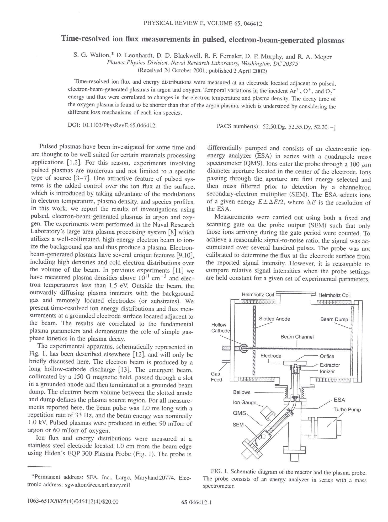
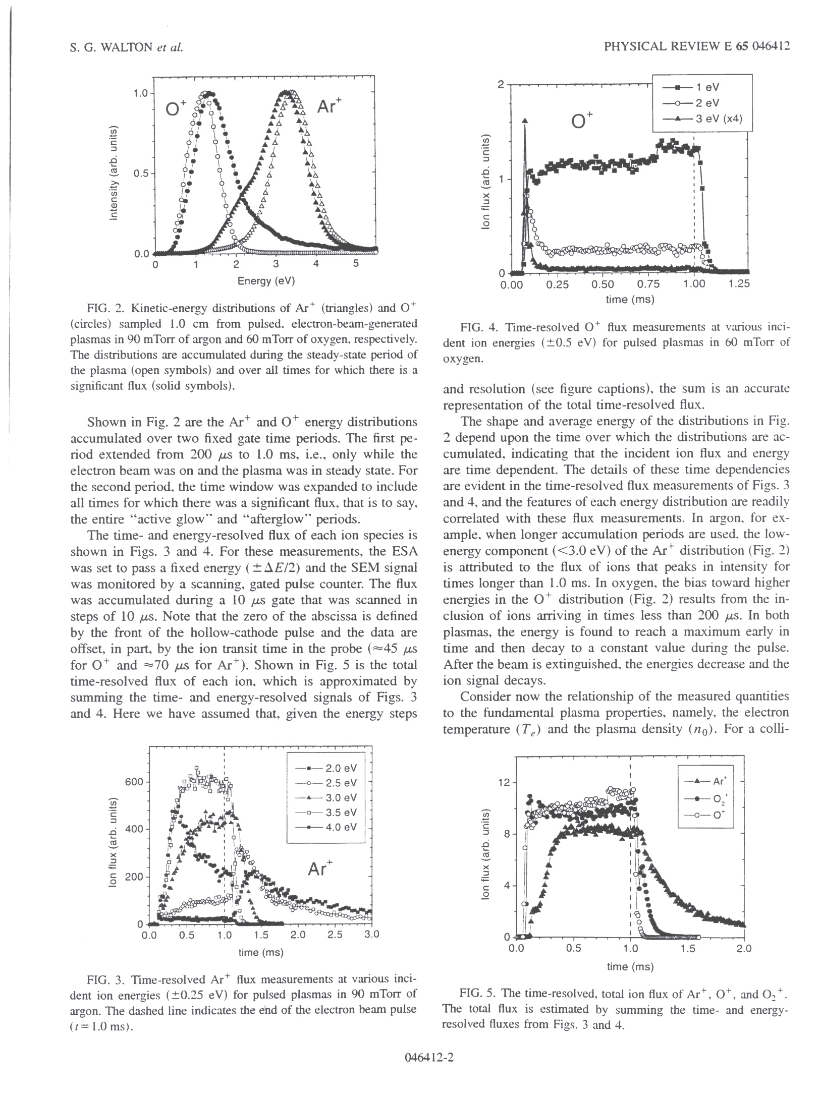
PHYSICAL REVIEW E, VOLUME 65,046412 PHYSICAL REVIEW E 65 046412S.G. WALTON et al. Time-resolved ion flux measurements in pulsed, electron-beam-generated plasmas S. G. Walton,* D. Leonhardt, D. D. Blackwell, R. F. Fernsler, D. P. Murphy, and R. A. Megerplasma Physics Division, Naval Research Laboratory, Washington, DC 20375(Received 24 October 2001; published 2 April 2002) Time-resolved ion flux and energy distributions were measured at an electrode located adjacent to pulsed,electron-beam-generated plasmas in argon and oxygen. Temporal variations in the incident Art, O*, and O+energy and flux were correlated to changes in the electron temperature and plasma density. The decay time ofthe oxygen plasma is found to be shorter than that of the argon plasma, which is understood by considering thedifferent loss mechanisms of each ion species. DOI: 10.1103/PhysRevE.65.046412 PACS number(s): 52.50.Dg,52.55.Dy, 52.20.-j Pulsed plasmas have been investigated for some time andare thought to be well suited for certain materials processingapplications [1,2]. For this reason, experiments involvingpulsed plasmas are numerous and not limited to a specifictype of source [3-7]. One attractive feature of pulsed sys-tems is the added control over the ion flux at the surface,which is introduced by taking advantage of the modulationsin electron temperature, plasma density, and species profiles.In this work, we report the results of investigations usingpulsed, electron-beam-generated plasmas in argon and oxy-gen. The experiments were performed in the Naval ResearchLaboratory’s large area plasma processing system [8] whichutilizes a well-collimated,high-energy electron beam to ion-ize the background gas and thus produce a plasma. Electron-beam-generated plasmas have several unique features [9,10],including high densities and cold electron distributions overthe volume of the beam. In previous experiments [11] wehave measured plasma densities above 10cm’and elec-tron temperatures less than 1.5 eV. Outside the beam, theoutwardly diffusing plasma interacts with the backgroundgas and remotely located electrodes (or substrates). Wepresent time-resolved ion energy distributions and flux mea-surements at a grounded electrode surface located adjacent tothe beam. The results are correlated to the fundamentalplasma parameters and demonstrate the role of simple gas-phase kinetics in the plasma decay. The experimental apparatus, schematically represented inFig. 1, has been described elsewhere [12], and will only bebriefly discussed here. The electron beam is produced by along hollow-cathode discharge [13]. The emergent beam,collimated by a 150 G magnetic field, passed through a slotin a grounded anode and then terminated at a grounded beamdump. The electron beam volume between the slotted anodeand dump defines the plasma source region. For all measure-ments reported here, the beam pulse was 1.0 ms long with arepetition rate of 33 Hz, and the beam energy was nominally1.0 kV. Pulsed plasmas were produced in either 90 mTorr ofargon or 60 mTorr of oxygen. Ion flux and energy distributions were measured at astainless steel electrode located 1.0 cm from the beam edgeusing Hiden`s EQP 300 Plasma Probe (Fig.1). The probe is ( *Permanent a d dress: S F A , In c ., L a r go, Ma r ylan d 20774. Ele c - t ronic address: s g walton@ccs.nrl.navy.m i l ) differentially pumped and consists of an electrostatic ion-energy analyzer (ESA) in series with a quadrupole massspectrometer (QMS). Ions enter the probe through a 100 umdiameter aperture located in the center of the electrode. Ionspassing through the aperture are first energy selected andthen mass filtered prior to detection by a channeltronsecondary-electron multiplier (SEM). The ESA selects ionsof a given energy E±AE/2, where AE is the resolution ofthe ESA. Measurements were carried out using both a fixed andscanning gate on the probe output (SEM) such that onlythose ions arriving during the gate period were counted. Toachieve a reasonable signal-to-noise ratio, the signal was ac-cumulated over several hundred pulses. The probe was notcalibrated to determine the flux at the electrode surface fromthe reported signal intensity. However, it is reasonable tocompare relative signal intensities when the probe settingsare held constant for a given set of experimental parameters. FIG. 1. Schematic diagram of the reactor and the plasma probe.The probe consists of an energy analyzer in series with a massspectrometer. FIG. 2. Kinetic-energy distributions of Ar*(triangles) and O*(circles) sampled 1.0 cm from pulsed. electron-beam-generatedplasmas in 90 mTorr of argon and 60 mTorr of oxygen, respectively.The distributions are accumulated during the steady-state period ofthe plasma (open symbols) and over all times for which there is asignificant flux (solid symbols). Shown in Fig. 2 are the Ar* and O* energy distributionsaccumulated over two fixed gate time periods. The first pe-riod extended from 200 us to 1.0 ms, i.e., only while theelectron beam was on and the plasma was in steady state. Forthe second period, the time window was expanded to includeall times for which there was a significant flux, that is to say,the entire “active glowand“afterglow" periods. The time- and energy-resolved flux of each ion species isshown in Figs. 3 and 4. For these measurements, the ESAwas set to pass a fixed energy (±AE/2) and the SEM signalwas monitored by a scanning, gated pulse counter. The fluxwas accumulated during a 10 us gate that was scanned insteps of 10 us. Note that the zero of the abscissa is definedby the front of the hollow-cathode pulse and the data areoffset, in part, by the ion transit time in the probe (≈45 usfor O+ and ≈70 us for Ar). Shown in Fig.5 is the totaltime-resolved flux of each ion, which is approximated bysumming the time- and energy-resolved signals of Figs. 3and 4. Here we have assumed that, given the energy steps FIG. 3. Time-resolved Ar+ flux measurements at various inci-dent ion energies (±0.25 eV) for pulsed plasmas in 90 mTorr ofargon. The dashed line indicates the end of the electron beam pulse(t=1.0 ms). FIG. 4. Time-resolved O+ flux measurements at various inci-dent ion energies (±0.5 eV) for pulsed plasmas in 60 mTorr ofoxygen. and resolution (see figure captions), the sum is an accuraterepresentation of the total time-resolved flux. The shape and average energy of the distributions in Fig.2 depend upon the time over which the distributions are ac-cumulated, indicating that the incident ion flux and energyare time dependent. The details of these time dependenciesare evident in the time-resolved flux measurements of Figs. 3and 4, and the features of each energy distribution are readilycorrelated with these flux measurements. In argon, for ex-ample, when longer accumulation periods are used. the low-energy component (<3.0 eV) of the Ar*distribution (Fig.2)is attributed to the flux of ions that peaks in intensity fortimes longer than 1.0 ms. In oxygen, the bias toward higherenergies in the O*distribution (Fig. 2) results from the in-clusion of ions arriving in times less than 200 us. In bothplasmas, the energy is found to reach a maximum early intime and then decay to a constant value during the pulse.After the beam is extinguished, the energies decrease and theion signal decays. Consider now the relationship of the measured quantitiesto the fundamental plasma properties, namely, the electrontemperature (Te) and the plasma density (no). For a colli- FIG. 5. The time-resolved, total ion flux of Art,O*, andO,+.The total flux is estimated by summing the time- and energy-resolved fluxes from Figs.3 and 4. ////$
确定
还剩1页未读,是否继续阅读?

产品配置单
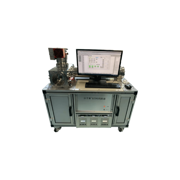
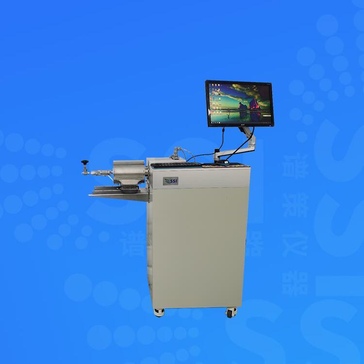
北京英格海德分析技术有限公司为您提供《脉冲电子束产生的等离子体的时间分辨离子流量分析》,该方案主要用于其他中--检测,参考标准--,《脉冲电子束产生的等离子体的时间分辨离子流量分析》用到的仪器有EQP等离子体质量和能量分析质谱仪
推荐专场
相关方案
更多