


方案详情
文
激光干涉测试方法常用于高精度测量和定位,这是由于这种方法具有较高的测量分辨率和精度,甚至可以用于大尺寸范围的测量。
本文重点讨论了外差式和单频式干涉仪的基本原理,并进行了相应的计量分析来描述激光干涉法的优势和局限性。
本文还讨论了光纤耦合式微型干涉仪的设计和功能,以及在显微技术、纳米技术和高精度机电一体化等方面的广泛应用。
方案详情

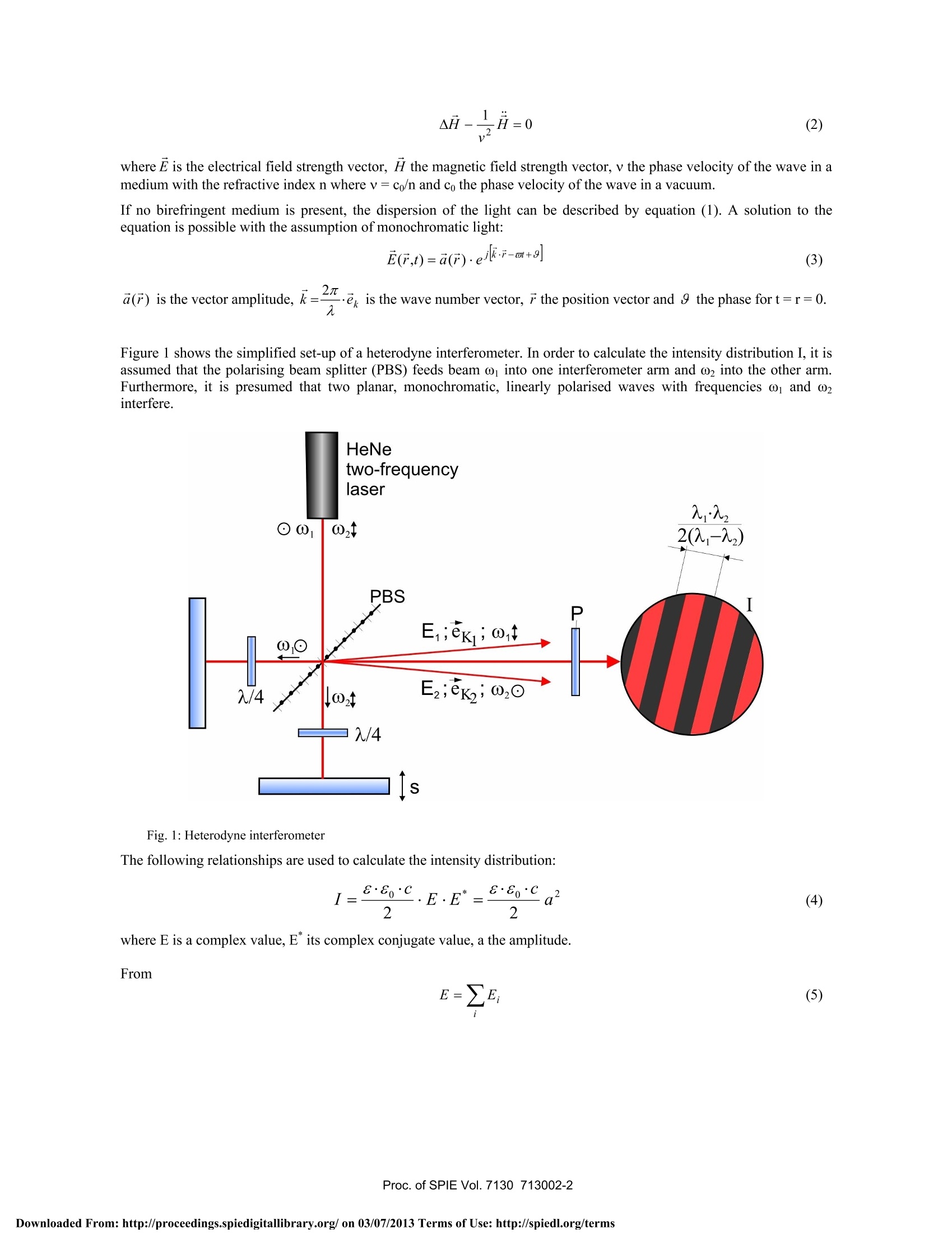
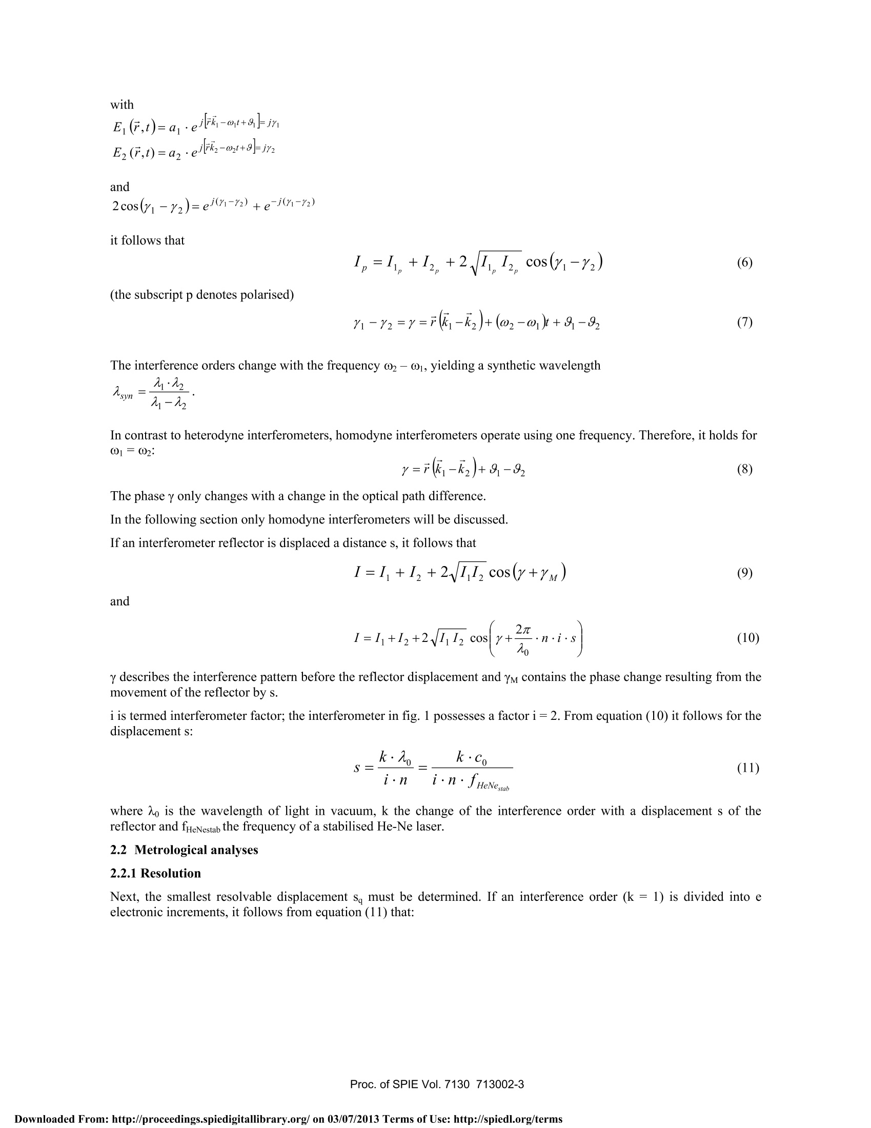
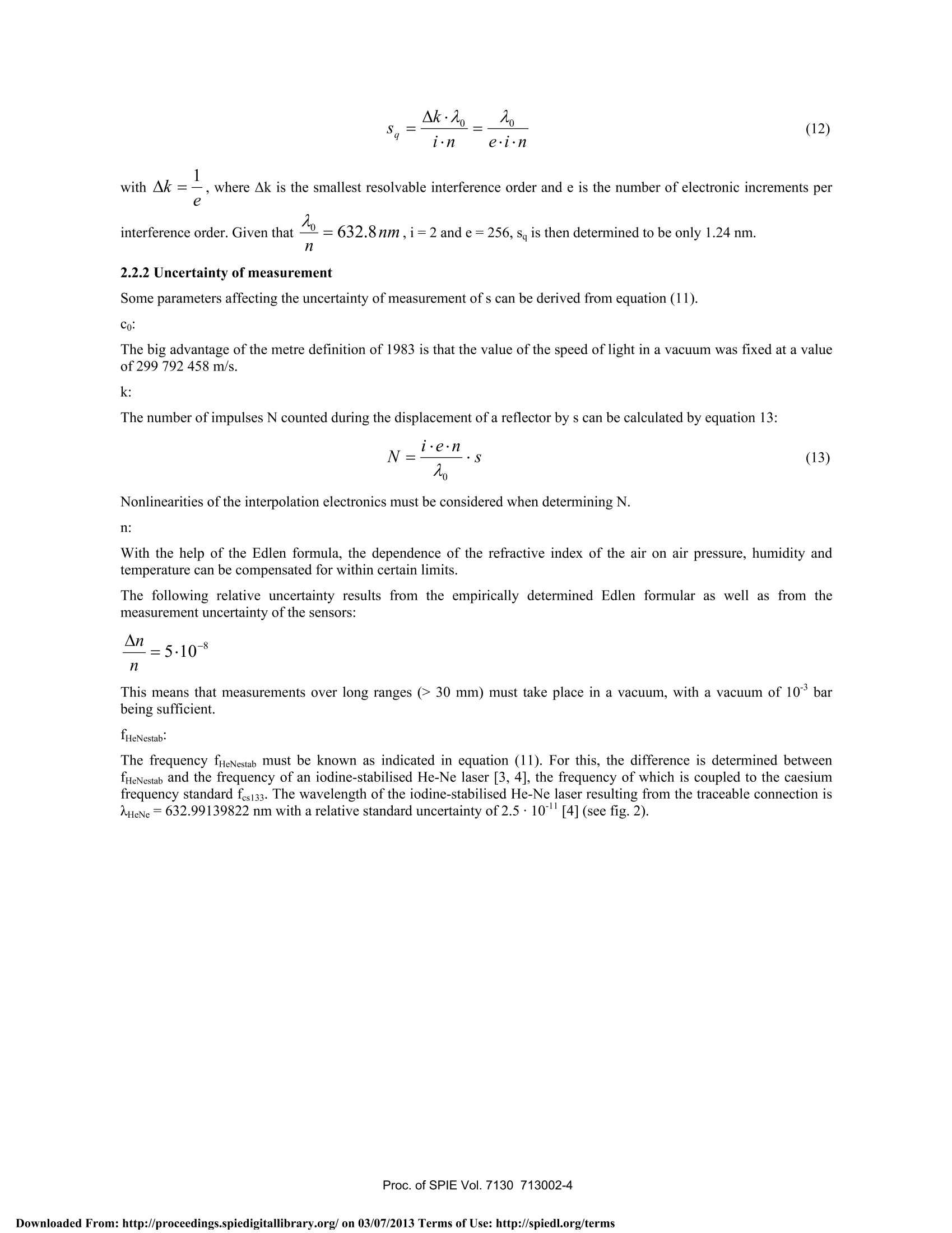
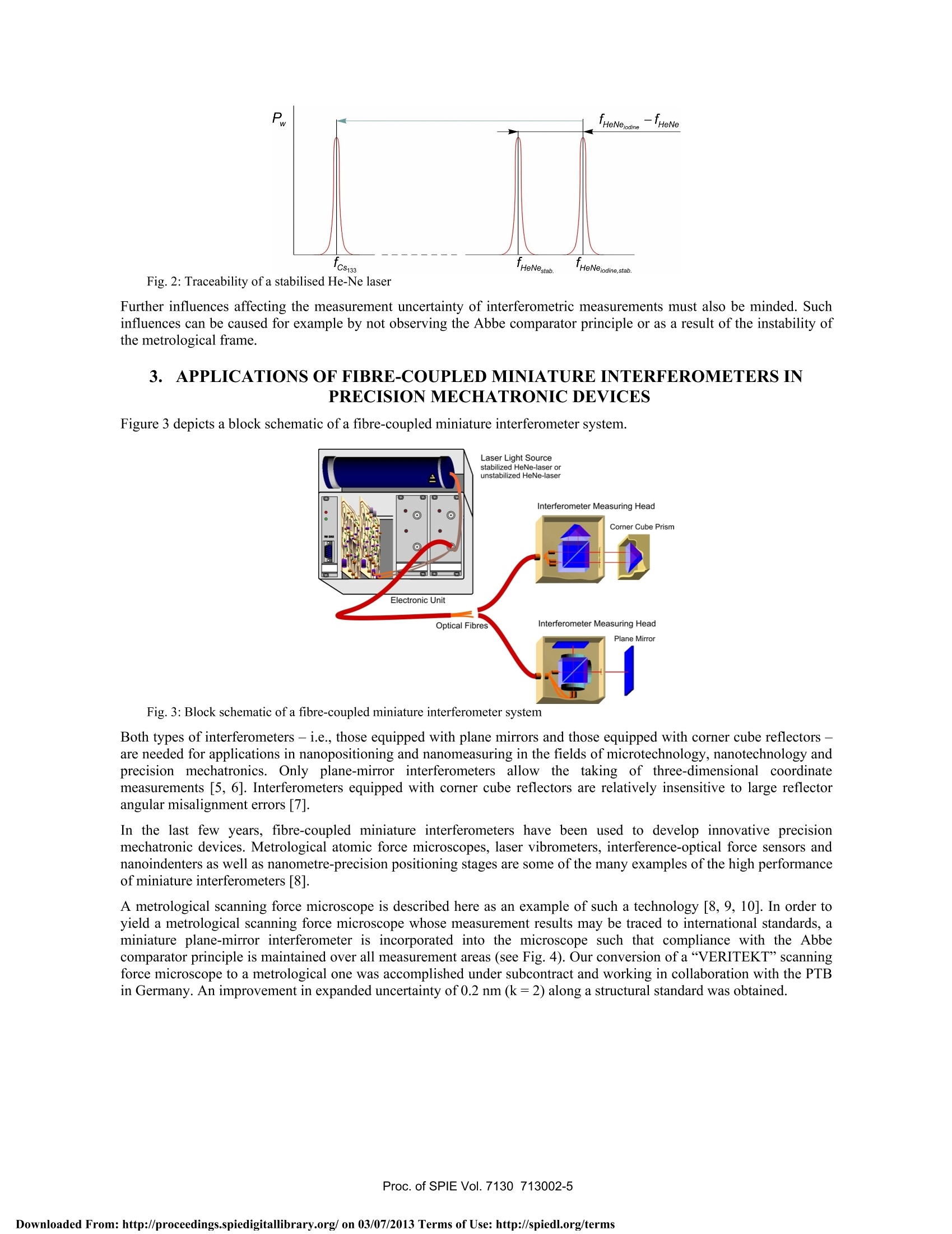
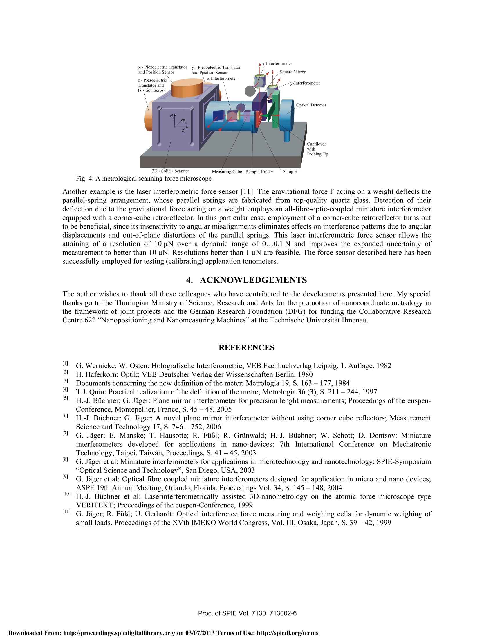
Keynote Paper Limits of precision measurements based on interferometers G. Jager* Technical University of Ilmenau; Institute of Process Measurement and Sensor TechnologyP.O.Box 100 565,98684 Ilmenau, Germany ABSTRACT Laser interferometric methods are employed in precision measurements and positioning tasks, since they provide themeans for attaining high metric resolution and precision, even over large measurement ranges. The most importantfundamental principles of heterodyne and homodyne interferometers are discussed. A metrological analysis makes itpossible to describe the advantages and limits of laser interferometry. The design and functionality of fibre-coupledminiature interferometers are described. The broad applicability of interferometers to microtechnology, nanotechnologyand precision mechatronics is explained. Keywords: Heterodyne and homodyne interferometers, metrological analysis, nanometrology, nano-precision devices 1. INTRODUCTION Today’s nanometrology limits the accuracy of precision engineering. These limits are based on the metre definition asredefined in 1983 as well as on the comparison between an iodine-stabilised helium-neon laser and a stabilised helium-neon laser to be calibrated, on the influence of the refractive index of the air, on the realisation of the Abbe principle andso on. Laser interferometric devices are employed in precision measurements and positioning tasks, since they provide ameans for attaining high metric resolution and precision, even over long measurement ranges. The versatility and broadapplicability of laser interferometers are unattainable using any other metrological methods. Laser interferometerssuitable for use in advanced areas of mecrotechnology, nanotechnology and precision mechatronics must have smallmeasuring heads that are insensitive to environmental effects. Miniature interferometers fulfilling this requirement havebeen developed at the Institute of Process Measurement and Sensor Technology of the Technische Universitat Ilmenauand are manufactured by SIOS Messtechnik GmbH. Their metrological benefits are due to their compact dimensions andtheir utilisation of optical fibres for coupling the laser light source, measuring head and electronic signal processing unit. The most important fundamental principles of heterodyne and homodyne interferometric devices are discussed. Theirbenefits and limitations are covered based on a metrological analysis and the broad applicability is explained by differentprecision mechatronic devices. 2. FUNDAMENTALS OFINTERFEROMETERS 2.1 The“Interference” in Interferometers The following section covers only interferometers with amplitude division. It is sensible to differentiate betweeninterferometers with neutral beam splitters and ones with polarising beam splitters. Homodyne interferometers usually use neutral beam splitters, whereas heterodyne devices require polarising elements. The dispersion of light is described by the Maxwellian wave equations. For homogenous isotropic non-conductors itholds [1,2]: Fourth International Symposium on Precision Mechanical Measurements, edited by Yetai Fei, Kuang-Chao Fan,Rongsheng Lu, Proc. of SPIE Vol. 7130,713002·C2008 SPIE·CCC code: 0277-786X/08/$18·doi: 10.1117/12.819537 where E is the electrical field strength vector, H the magnetic field strength vector, v the phase velocity of the wave in amedium with the refractive index n where v=co/n and co the phase velocity of the wave in a vacuum. If no birefringent medium is present, the dispersion of the light can be described by equation (1). A solution to theequation is possible with the assumption of monochromatic light: a(r) is the vector amplitude, k2=n-e is the wave number vector, r the position vector and 9 the phase for t=r=0. Figure 1 shows the simplified set-up of a heterodyne interferometer. In order to calculate the intensity distribution I, it isassumed that the polarising beam splitter (PBS) feeds beam ω into one interferometer arm and into the other arm.Furthermore, it is presumed that two planar, monochromatic, linearly polarised waves with frequencies ω and ω2interfere. Fig. 1: Heterodyne interferometerThe following relationships are used to calculate the intensity distribution: where E is a complex value,E"its complex conjugate value, a the amplitude. From with and it follows that (the subscript p denotes polarised) The interference orders change with the frequency ω2-01, yielding a synthetic wavelength In contrast to heterodyne interferometers, homodyne interferometers operate using one frequency. Therefore, it holds for01=02: The phase y only changes with a change in the optical path difference. In the following section only homodyne interferometers will be discussed. If an interferometer reflector is displaced a distance s, it follows that and y describes the interference pattern before the reflector displacement and Ym contains the phase change resulting from themovement of the reflector by S. i is termed interferometer factor; the interferometer in fig. 1 possesses a factor i=2. From equation (10) it follows for thedisplacement s: where Ao is the wavelength of light in vacuum, k the change of the interference order with a displacement s of thereflector and fHeNestab the frequency of a stabilised He-Ne laser. 2.2 Metrological analyses 2.2.1 Resolution Next, the smallest resolvable displacement sg must be determined. If an interference order (k=1) is divided into eelectronic increments, it follows from equation (11) that: with Ak=-, where Ak is the smallest resolvable interference order and e is the number of electronic increments pere 2.2.2 Uncertainty of measurement Some parameters affecting the uncertainty of measurement of s can be derived from equation (11). Co: The big advantage of the metre definition of 1983 is that the value of the speed of light in a vacuum was fixed at a valueof 299 792 458 m/s. k: The number of impulses N counted during the displacement of a reflector by s can be calculated by equation 13: Nonlinearities of the interpolation electronics must be considered when determining N. n: With the help of the Edlen formula, the dependence of the refractive index of the air on air pressure, humidity andtemperature can be compensated for within certain limits. The following relative uncertainty results from the empirically determined Edlen formular as well as from themeasurement uncertainty of the sensors: n This means that measurements over long ranges (>30 mm) must take place in a vacuum, with a vacuum of 10barbeing sufficient. 1HeNestab. The frequency fHeNestab must be known as indicated in equation (11). For this, the difference is determined betweenfHeNestab and the frequency of an iodine-stabilised He-Ne laser [3, 4], the frequency of which is coupled to the caesiumfrequency standard fes133. The wavelength of the iodine-stabilised He-Ne laser resulting from the traceable connection isAHeNe=632.99139822 nm with a relative standard uncertainty of 2.5· 10[4](see fig. 2). Fig.2: Traceability of a stabilised He-Ne laser Further influences affecting the measurement uncertainty of interferometric measurements must also be minded. Suchinfluences can be caused for example by not observing the Abbe comparator principle or as a result of the instability ofthe metrological frame. 3. APPLICATIONS OF FIBRE-COUPLED MINIATURE INTERFEROMETERS INPRECISION MECHATRONIC DEVICES Figure 3 depicts a block schematic of a fibre-coupled miniature interferometer system. Fig.3: Block schematic of a fibre-coupled miniature interferometer system Both types of interferometers - i.e.,those equipped with plane mirrors and those equipped with corner cube reflectors -are needed for applications in nanopositioning and nanomeasuring in the fields of microtechnology, nanotechnology andprecision mechatronics. Only plane-mirror interferometers allow theetaking of three-dimensional coordinatemeasurements [5, 6].Interferometers equipped with corner cube reflectors are relatively insensitive to large reflectorangular misalignment errors [7]. In the last few years, fibre-coupled miniature interferometers have been used to develop innovative precisionmechatronic devices. Metrological atomic force microscopes, laser vibrometers, interference-optical force sensors andnanoindenters as well as nanometre-precision positioning stages are some of the many examples of the high performanceof miniature interferometers [8]. A metrological scanning force microscope is described here as an example of such a technology[8, 9, 10]. In order toyield a metrological scanning force microscope whose measurement results may be traced to international standards, aminiature plane-mirror interferometer is incorporated into the microscope such that compliance with the Abbecomparator principle is maintained over all measurement areas (see Fig.4). Our conversion of a“VERITEKT”scanningforce microscope to a metrological one was accomplished under subcontract and working in collaboration with the PTBin Germany. An improvement in expanded uncertainty of 0.2 nm(k=2)along a structural standard was obtained. 3D-Solid-Scanner Measuring Cube Sample Holder Sample Fig. 4: A metrological scanning force microscope Another example is the laser interferometric force sensor [11]. The gravitational force F acting on a weight deflects theparallel-spring arrangement, whose parallel springs are fabricated from top-quality quartz glass. Detection of theirdeflection due to the gravitational force acting on a weight employs an all-fibre-optic-coupled miniature interferometerequipped with a corner-cube retroreflector. In this particular case, employment of a corner-cube retroreflector turns outto be beneficial, since its insensitivity to angular misalignments eliminates effects on interference patterns due to angulardisplacements and out-of-plane distortions of the parallel springs. This laser interferometric force sensor allows theattaining of a resolution of 10 uN over a dynamic range of 0...0.1 N and improves the expanded uncertainty of)fmeasurement to better than 10 uN. Resolutions better than 1 uN are feasible. The force sensor described here has beensuccessfully employed for testing (calibrating) applanation tonometers. 4. ACKNOWLEDGEMENTS The author wishes to thank all those colleagues who have contributed to the developments presented here. My specialthanks go to the Thuringian Ministry of Science, Research and Arts for the promotion of nanocoordinate metrology inthe framework of joint projects and the German Research Foundation (DFG) for funding the Collaborative ResearchCentre 622“Nanopositioning and Nanomeasuring Machines" at the Technische Universitat Ilmenau. REFERENCES G. Wernicke; W.Osten: Holografische Interferometrie; VEB Fachbuchverlag Leipzig, 1. Auflage, 1982 H. Haferkorn: Optik; VEB Deutscher Verlag der Wissenschaften Berlin, 1980 Documents concerning the new definition of the meter; Metrologia 19, S. 163-177,1984 T.J. Quin: Practical realization of the definition of the metre; Metrologia 36 (3), S. 211-244,1997 H.-J. Buchner; G. Jager: Plane mirror interferometer for precision lenght measurements; Proceedings of the euspen-Conference, Montepellier, France, S. 45 -48, 2005 [6] H.-J. Bichner; G. Jager: A novel plane mirror interferometer without using corner cube reflectors; MeasurementScience and Technology 17, S. 746-752,2006 [7] G. Jager; E. Manske; T. Hausotte; R. FuBl; R. Grinwald; H.-J. Buchner; W. Schott; D. Dontsov: Miniatureinterferometers developed for applications in nano-devices; 7th International Conference on MechatronicTechnology, Taipei, Taiwan, Proceedings, S. 41- 45, 2003 [8] G. Jager et al: Miniature interferometers for applications in microtechnology and nanotechnology; SPIE-Symposium“Optical Science and Technology”, San Diego, USA, 2003 [9] G. Jager et al: Optical fibre coupled miniature interferometers designed for application in micro and nano devices;ASPE 19th Annual Meeting, Orlando, Florida, Proceedings Vol. 34, S. 145-148,2004 [10]H.-J. Buchner et al: Laserinterferometrically assisted 3D-nanometrology on the atomic force microscope typeVERITEKT; Proceedings of the euspen-Conference, 1999 ( [11] G. Jager; R . FuBl; U. Gerhardt: Optical interference force measuring and weighing cells for dynamic weighi n g ofsmall l oads. Proceedings of the XVth IMEKO World Congress, Vol. I I I, Osaka, Japan, S. 39- 42, 1999 ) *gerd.jaeger@tu-ilmenau.de; phone + fax +roc. of SPIE Vol.ownloaded From: http://proceedings.spiedigitallibrary.org/ on Terms of Use: http://spiedl.org/terms Proc. of SPIE Vol. ownloaded From: http://proceedings.spiedigitallibrary.org/ on Terms of Use: http://spiedl.org/terms
确定
还剩4页未读,是否继续阅读?

产品配置单
上海依阳实业有限公司为您提供《激光干涉仪精确测量的局限性》,该方案主要用于其他中检测,参考标准--,《激光干涉仪精确测量的局限性》用到的仪器有激光干涉法热膨胀测试系统
推荐专场
相关方案
更多
该厂商其他方案
更多