


本方案设计了一种高速热膨胀仪用于固体试样热膨胀和热收缩的高精度测量。试样长度的测量采用差分干涉法,具有0.3nm的分辨率和30nm的测量重复性。温度控制则采用感应加热和气体冷却方式实现,最大加热速度约为100K/s,最大冷却速度为50K/s。对于非导体试样的加热则在试样周围增加金属环的间接加热方式。整个测试系统可以在不同气氛环境下进行运行,包括氧气环境气氛,最大温度可以达到1600℃。
方案详情

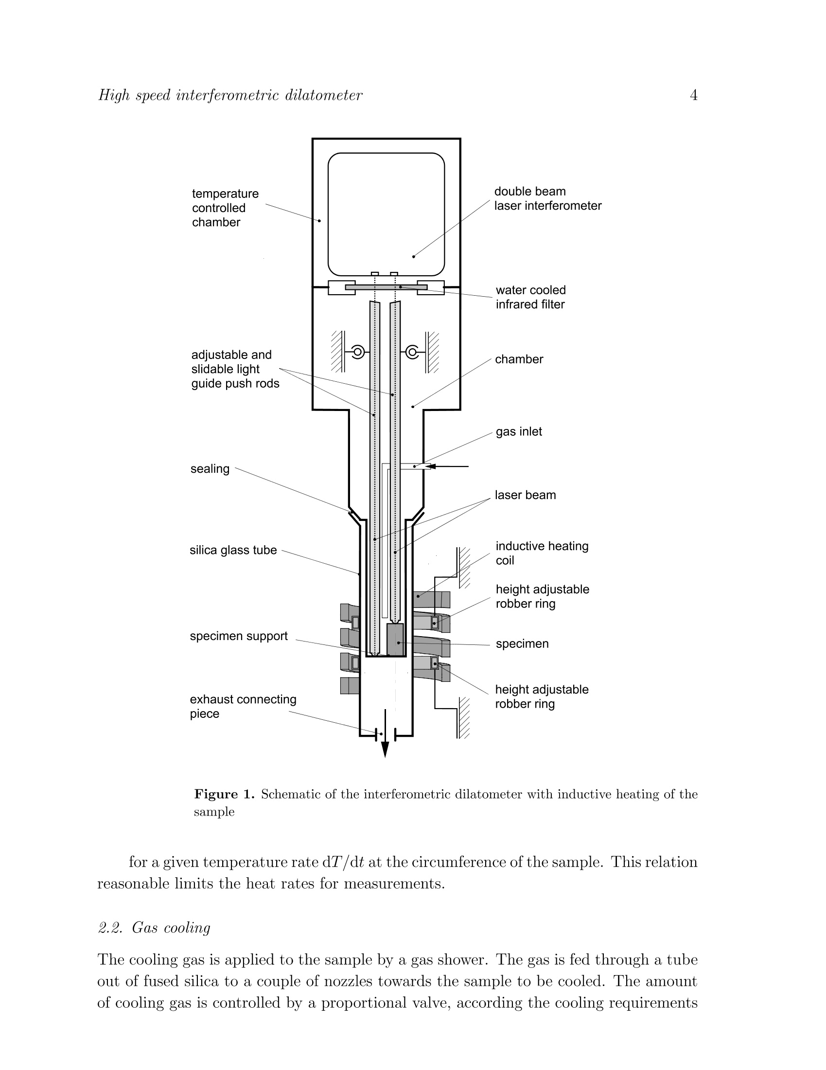
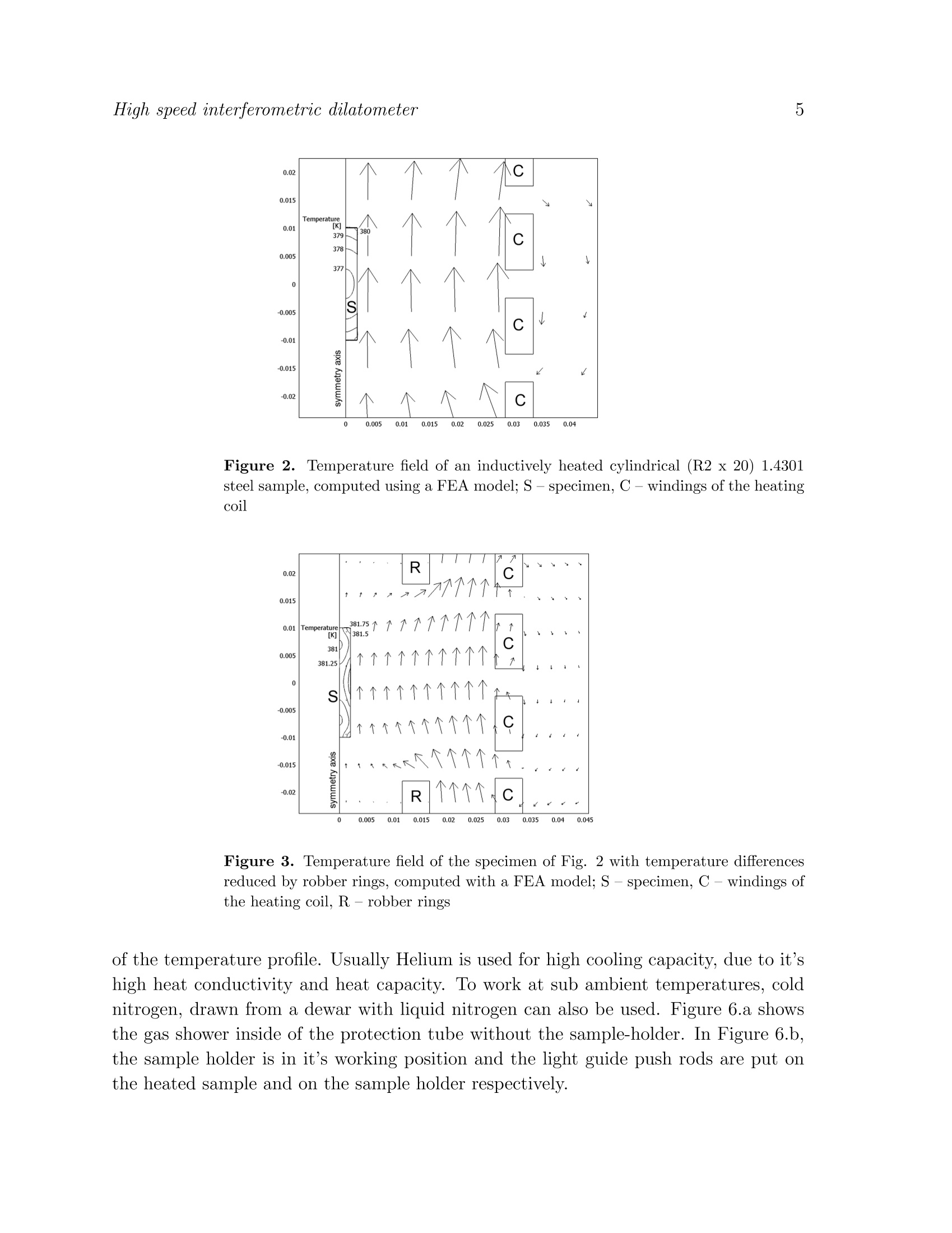
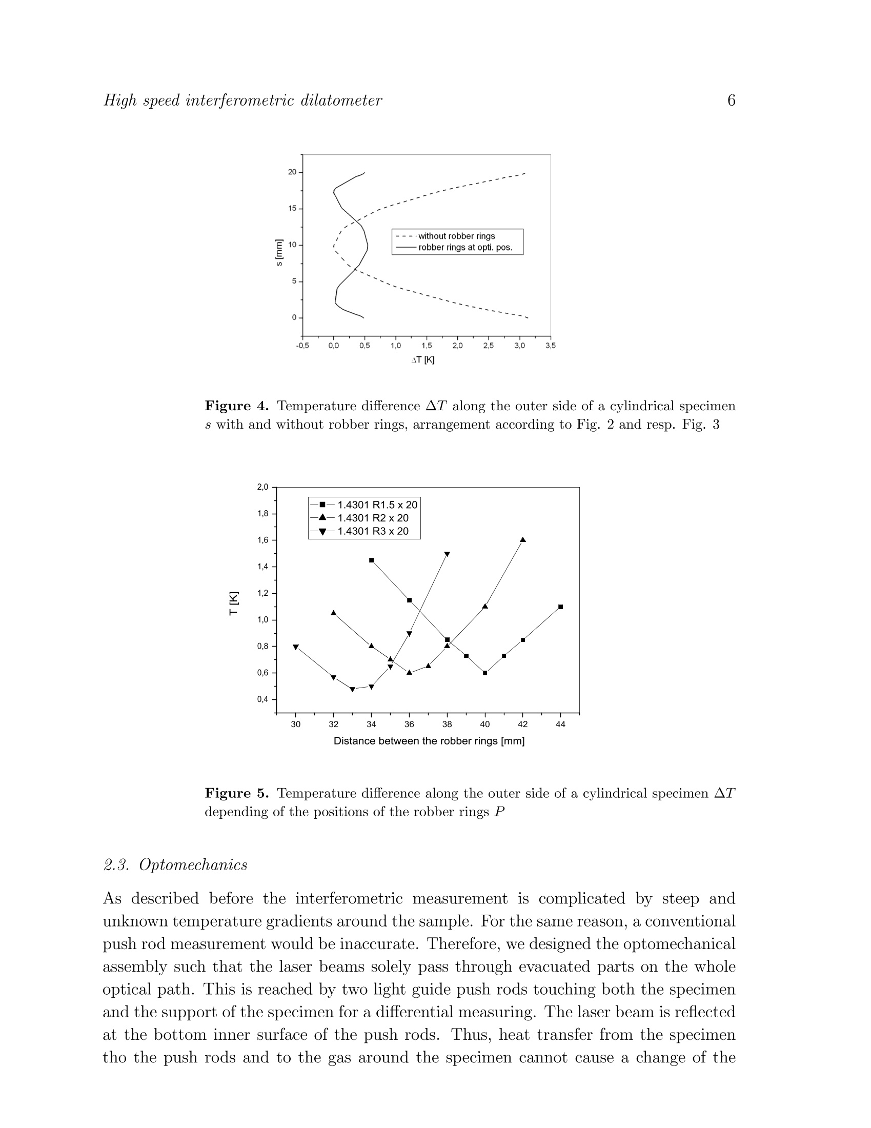
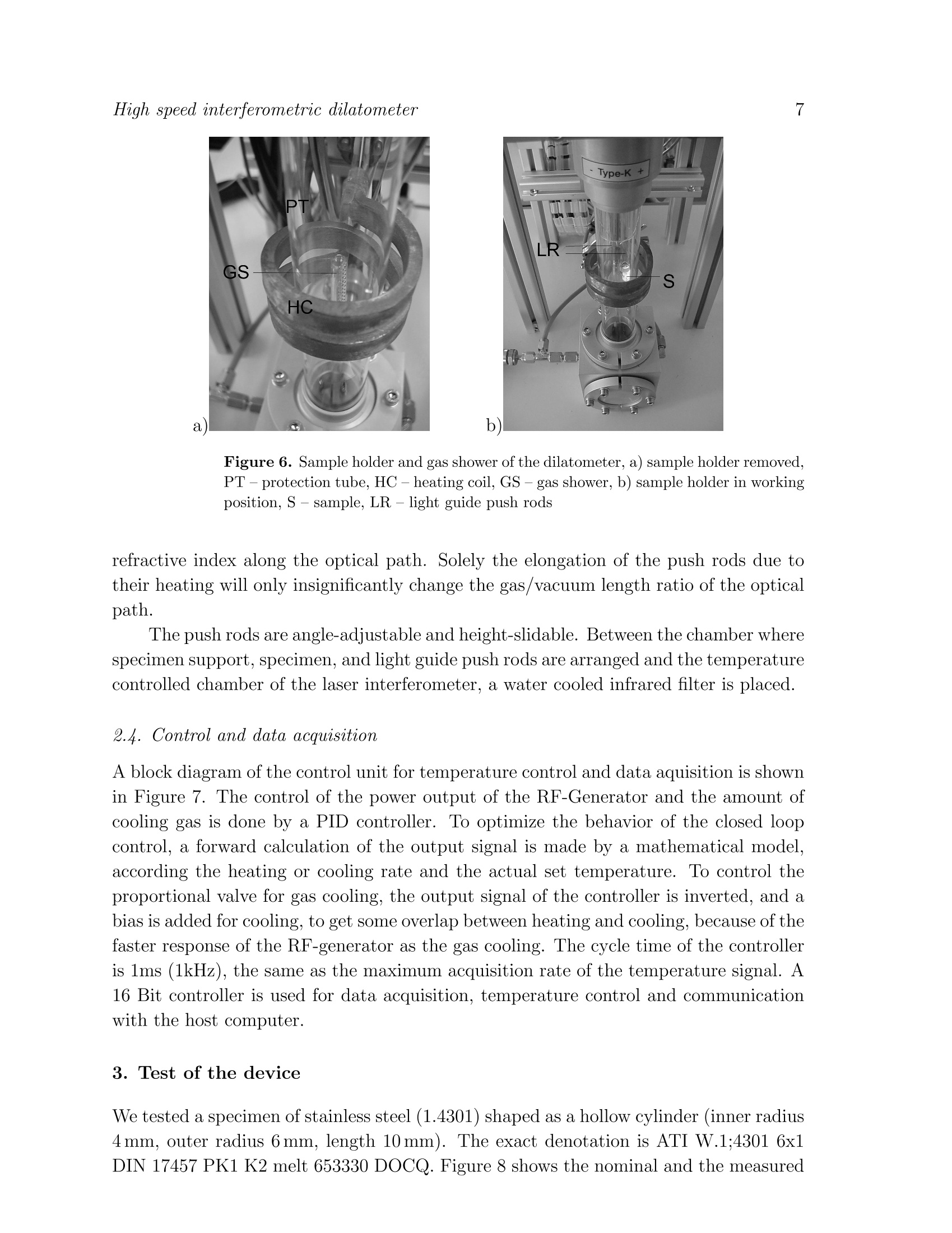
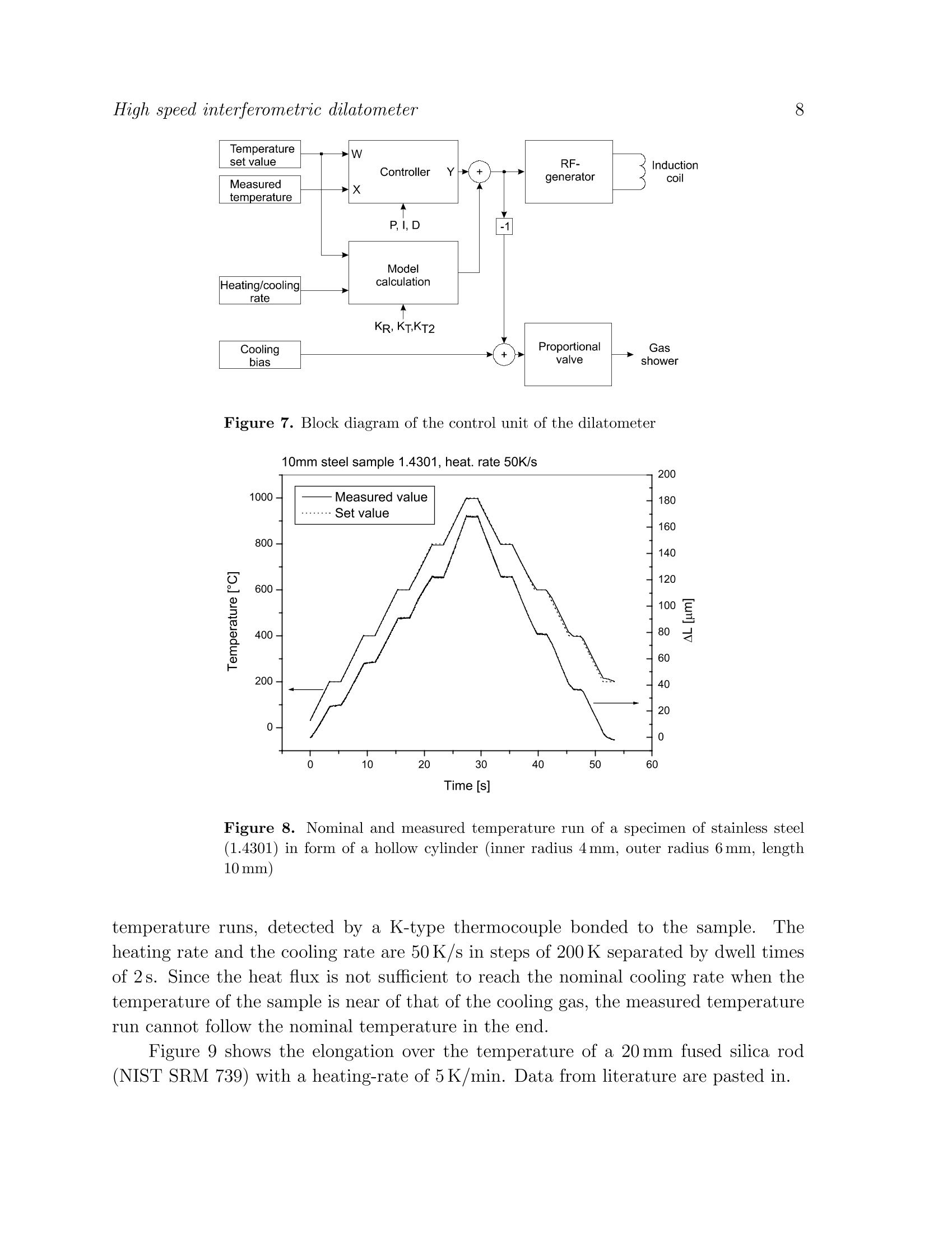
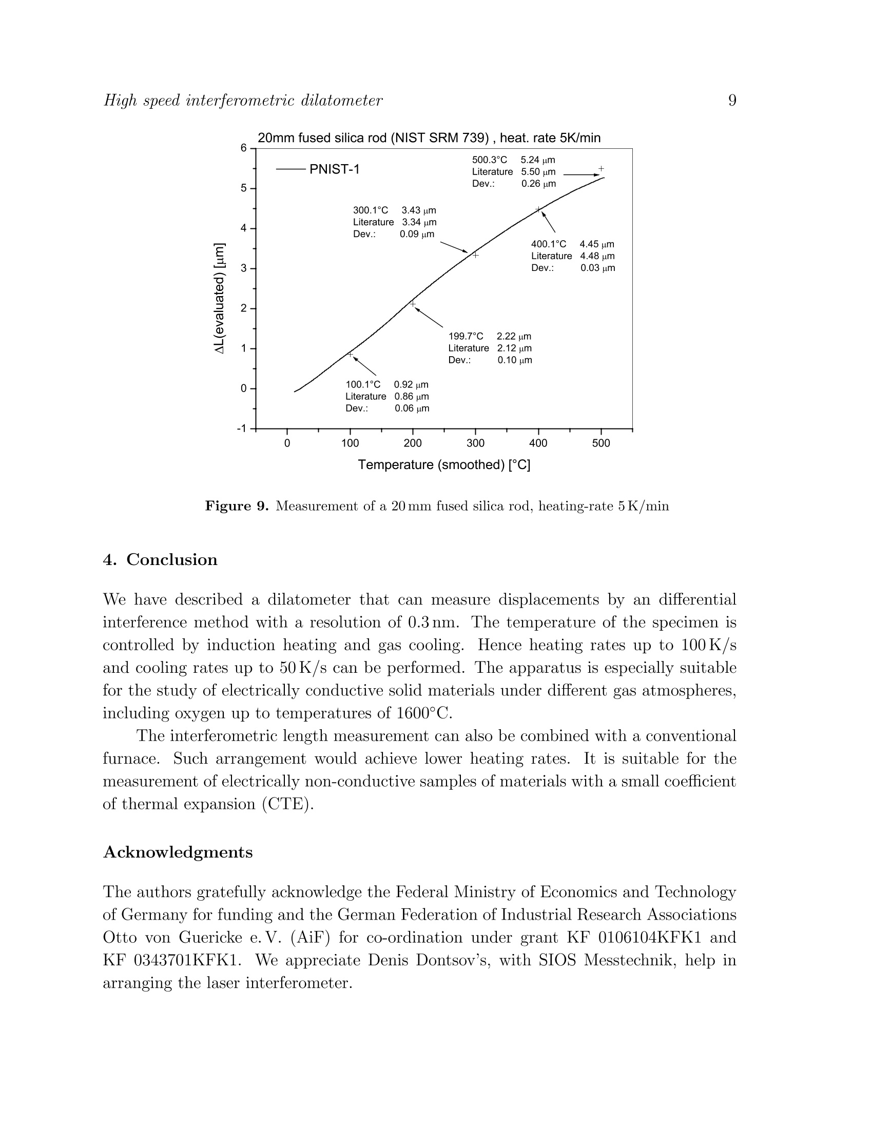
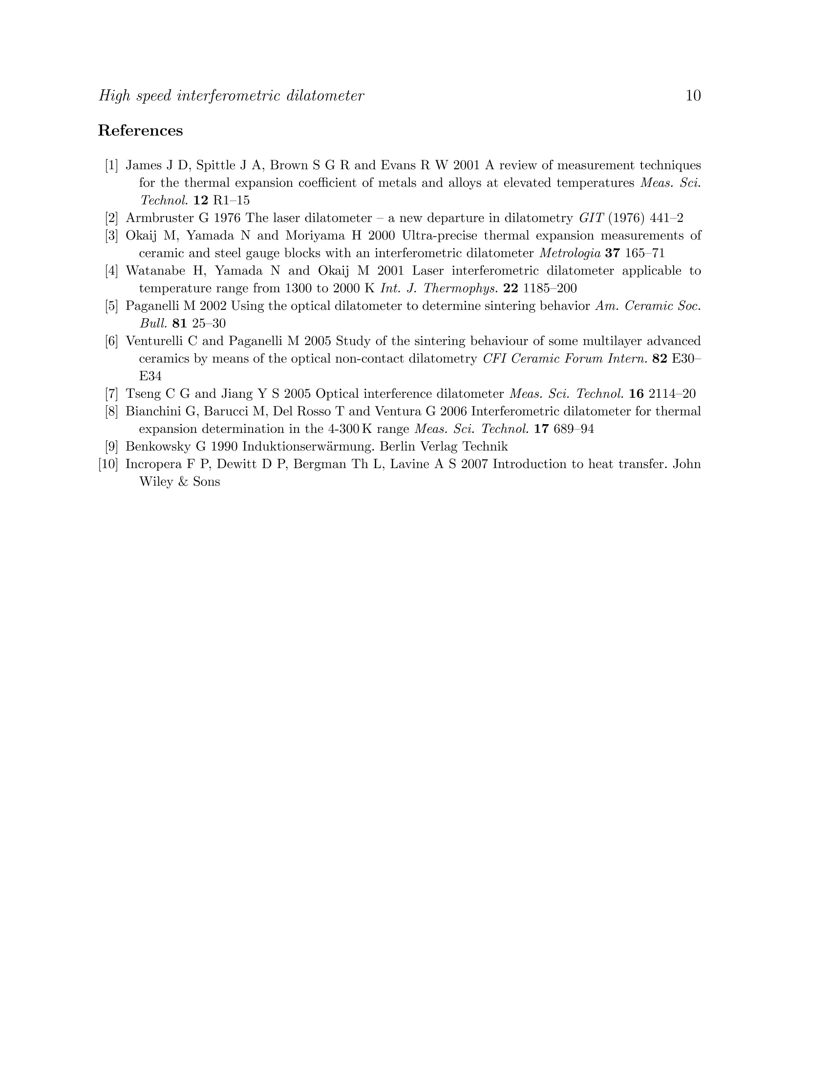
2 3High speed interferometric dilatometer A high speed interferometric dilatometer based oninductive heating of the specimen H Neubertl, E Bindl, M Mehnertl, H Radel, CLinseis’ Dresden University of Technology, Institute of Electromechanical and ElectronicDesign, D-01062 Dresden, Germany ”Linseis GmbH, Vielitzer StraBe 43, D-95100 Selb, Germany E-mail: holger.neubert@tu-dresden.de Abstract. A highi speedddilatometerhasbbeen designed for high1 precisionmeasurements of the thermal expansion/contraction of solid samples. The length ofthe specimens is measured by an differential interference method with a resolution of0.3nm and a reproducibility of 30 nm..The temperature is controlled by inductionheating and gas cooling. The maximum heating rate is about 100 K/s, the maximumcooling rate 50 K/s. Electrically non-conductive specimens can be heated indirectly viametallic rings around the specimen. The system enables measurements under differentgas atmospheres, including oxygen up to temperatures of 1600°C. Keywords: optical dilatometer, induction heating, laser interferometer High speed interferometric dilatometer 1. Introduction Dilatometers are generally used for measuring the length of a specimen within atemperature range. This allows to derive the coefficient of thermal expansion (CTE) andto find material phase changes. The aim of this study is to design and test a high speedhigh precision optical dilatometer based on inductive heating of electrically conductivesolid specimens for temperatures up to 1600°C. A typical dilatometer heats the specimen using a furnace. The mass of the furnaceis considerably larger than the mass of the specimen. That limits the heating speed toabout 1K/s. After having taken a measurement, much time is needed for cooling downthe furnace, before the following measurement can be started. Unfortunately the heatthe furnace produces also heats the dilatometer as a whole. Although this is a slowprocess but it causes drifting,which is to be a remarkable disadvantage when a series ofmeasurements is to be taken. That makes it desirable to focus the heat on the specimenin order to achieve a higher heating rate and a better accuracy and reproducibility aswell. For measuring of the length of the specimen mechanical and optical principles areknown. James et al [1] gave a survey of measurement techniques of dilatometers. Widelyused are silica push rods that touch the specimen and measure its elongation using alinear variable differential transformer (LVDT) displacement transducer. The thermalexpansions of the push rod and of the specimen’s support have some influence on thereadings. Therefore the behavior of the support and the push rod must be known andit must be reproducible. Push rod dilatometers enable a resolution of 10 nm and areproducibility of 150 nm to be achieved. For high precision measurements optical measurement techniques are consideredappropriate, based on the optical interference of light reflected from the specimen.Laser interferometric dilatometers were proposed in the 1970s 2]. The lack of adequatemirrors limited the temperature to 1350 K maximum. Furnaces were used for heating.From 2000, Okaij et al [3] and Watanabe et al [4] have introduced a series of laserinterferometric dilatometers to measure the CTE of solids. In 2005 Tseng and Jiang 7presented an optical interference dilatometer based on shadow moire technique.[8etal designed an optical dilatometer based on a Michelson interferometer for the 4...300Ktemperature range. The well-established optical arrangements require an optical path of constant or atleast stationary refractive index with the same distribution at the way to and from thespecimen. That is ensured by using a furnace for heating the gas around the sample, orby placing the sample in a vacuum. Unfortunately an inductively heated sample heatsthe surrounding gas by conduction so that convection will emerge. Steep gradients oftemperature will occur,and of the refractive index as well as the refractive index of a gasdepends on its density. Hence the gas around the specimen distorts the measurement.Calibration is not helpful due to the dependence of the temperature field on the gasmixture and on the heating and cooling rates. Therefore, for fast inductive heating of the sample together with optical measurement, an arrangement is needed that eliminatesthe influence of the gas atmosphere around the specimen. 2. Device description Figure 1 shows a schematic of the interferometric dilatometer with inductive heatingof the sample. Basically, it includes the following modules: the gas chamber with thespecimen holder, the inductive heating device with a HF power generator, a coil and so-called robber rings, the gas shower for cooling the sample, the double beam differentiallaser interferometer with two light guide push rods, and the control and data acquisitionunit. The modules are described in detail in the following. 2.1. Inductive heating The inductive heating assembly consists of a high frequency (HF) power generator, afixed heating coil and two height-movable robber rings to form the electro-magneticfield. Both the heating coil and the robber rings are water-cooled. The specimen to bemeasured is located on the axis of the heating coil and robber rings whereas the silicatube is slightly shifted out of the axis to contain both light guide rods. The working frequency of the induction heating coil is about 200 kHz. Hence thedepth of penetration 6 of the eddy currents is not greater than about 100 um 9]: with the electrical resistivity p and the magnetic permeability u of the material and the generator frequency f. Therefore heat is induced close to the surface of the specimen.The corpus of the specimen is mainly heated by diffusion. At the edges of cylindricalspecimens the temperature will be raised. This is shown by a FEA simulation in Figure2. Local field weakening by the robber rings counteracts the temperature raising andreduces the temperature difference along the specimen. Figure 3 and 4 illustrate this bythe example of a specimen made of 1.4301 steel. The optimum position of the robberrings for a minimum of the temperature difference along the surface of the specimendepends on the dimensions and on the material of the specimen as shown in Figure 5. Inoptimum position of the robber rings, the temperature at the edges of the specimen isequal to that in the middle of the cylinder surface. However, a disadvantage of the robberrings is that they reduce the maximum heating rate and get heated up themselves. The temperature difference AT emerging between the inner axis of the specimenand its circumference depends on the specific heat capacity cp, the density p, the thermalconductivity 入 and the radius R of the sample. Deduced from the heat equation incylindrical coordinates, the radial temperature difference T, is [10]: Figure 1. Schematic of the interferometric dilatometer with inductive heating of thesample for a given temperature rate dT/dt at the circumference of the sample. This relationreasonable limits the heat rates for measurements. 2.2. Gas cooling The cooling gas is applied to the sample by a gas shower. The gas is fed through a tubeout of fused silica to a couple of nozzles towards the sample to be cooled. The amountof cooling gas is controlled by a proportional valve, according the cooling requirements Figure 2. Temperature field of an inductively heated cylindrical (R2 x 20) 1.4301steel sample, computed using a FEA model; S --S ,C-windings of the heatincoil Figure 3. Temperature field of the specimen of Fig. 2 with temperature differencesreduced by robber rings, computed with a FEA model; S - specimen, C -windings ofthe heating coil, R-robber rings of the temperature profile. Usually Helium is used for high cooling capacity, due to it’shigh heat conductivity and heat capacity. To work at sub ambient temperatures, coldnitrogen, drawn from a dewar with liquid nitrogen can also be used. Figure 6.a showsthe gas shower inside of the protection tube without the sample-holder. In Figure 6.b,the sample holder is in it’s working position and the light guide push rods are put onthe heated sample and on the sample holder respectively. Figure 4. Temperature difference AT along the outer side of a cylindrical specimens with and without robber rings, arrangement according to Fig. 2 and resp. Fig. 3 Figure 5. Temperature difference along the outer side of a cylindrical specimen ▲Tdepending of the positions of the robber rings P 2.3. Optomechanics As described before the interferometric measurement is complicated by steep andunknown temperature gradients around the sample. For the same reason, a conventionalpush rod measurement would be inaccurate. Therefore, we designed the optomechanicalassembly such that the laser beams solely pass through evacuated parts on the wholeoptical path. This is reached by two light guide push rods touching both the specimenand the support of the specimen for a differential measuring. The laser beam is reflectedat the bottom inner surface of the push rods. Thus, heat transfer from the specimentho the push rods and to the gas around the specimen cannot cause a change of the High speed interferometric dilatometer a Figure 6. Sample holder and gas shower of the dilatometer, a) sample holder removed,PT -protection tube, HC-heating coil, GS-gas shower, b) sample holder in workingposition, S -sample,LR -light guide push rods refractive index along the optical path. Solely the elongation of the push rods due totheir heating will only insignificantly change the gas/vacuum length ratio of the opticalpath. The push rods are angle-adjustable and height-slidable. Between the chamber wherespecimen support, specimen, and light guide push rods are arranged and the temperaturecontrolled chamber of the laser interferometer, a water cooled infrared filter is placed. 2.4. Control and data acquisition A block diagram of the control unit for temperature control and data aquisition is shownin Figure 7. The control of the power output of the RF-Generator and the amount ofcooling gas is done by a PID controller. To optimize the behavior of the closed loopcontrol, a forward calculation of the output signal is made by a mathematical model,according the heating or cooling rate and the actual set temperature. To control theproportional valve for gas cooling, the output signal of the controller is inverted, and abias is added for cooling, to get some overlap between heating and cooling, because of thefaster response of the RF-generator as the gas cooling. The cycle time of the controlleris 1ms (1kHz), the same as the maximum acquisition rate of the temperature signal. A16 Bit controller is used for data acquisition, temperature control and communicationwith the host computer. 3. Test of the device We tested a specimen of stainless steel (1.4301) shaped as a hollow cylinder (inner radius4mm, outer radius 6 mm, length 10 mm). The exact denotation is ATI W.1;4301 6x1DIN 17457 PK1 K2 melt 653330 DOCQ. Figure 8 shows the nominal and the measured High speed interferometric dilatometer Figure 7. Block diagram of the control unit of the dilatometer 10mm steel sample 1.4301, heat. rate 50K/s Time [s] Figure 8. Nominal and measured temperature run of a specimen of stainless steel(1.4301) in form of a hollow cylinder (inner radius 4 mm, outer radius 6 mm, length10 mm) temperature runs, detected by a K-type thermocouple bonded to the sample.Theheating rate and the cooling rate are 50K/s in steps of 200 K separated by dwell timesof 2s. Since the heat flux is not sufficient to reach the nominal cooling rate when thetemperature of the sample is near of that of the cooling gas, the measured temperaturerun cannot follow the nominal temperature in the end. Figure 9 shows the elongation over the temperature of a 20 mm fused silica rod(NIST SRM 739) with a heating-rate of 5K/min. Data from literature are pasted in. Figure 9. Measurement of a 20 mm fused silica rod, heating-rate 5K/min 4. Conclusion We have described a dilatometer that can measure displacements by an differentialinterference method with a resolution of 0.3 nm. The temperature of the specimen iscontrolled by induction heating and gas cooling. Hence heating rates up to 100 K/sand cooling rates up to 50 K/s can be performed. The apparatus is especially suitablefor the study of electrically conductive solid materials under different gas atmospheres,including oxygen up to temperatures of 1600°C. The interferometric length measurement can also be combined with a conventionalfurnace.:. Such arrangement would achieve lower heating rates.It is suitable for themeasurement of electrically non-conductive samples of materials with a small coefficientof thermal expansion (CTE). Acknowledgments The authors gratefully acknowledge the Federal Ministry of Economics and Technologyof Germany for funding and the German Federation of Industrial Research AssociationsOtto von Guericke e.V. (AiF) for co-ordination under grant KF 0106104KFK1 andKF 0343701KFK1. We appreciate Denis Dontsov's, with SIOS Messtechnik, help inarranging the laser interferometer. ( References ) 1] James J D, Spittle J A, Brown S G R and Evans R W 2001 A review of measurement techniquesfor the thermal expansion coefficient of metals and alloys at elevated temperatures Meas. Sci.Technol.12 R1-15 2Armbruster G 1976 The laser dilatometer - a new departure in dilatometry GIT (1976) 441-2 3]Okaij M, Yamada N and Moriyama H 2000 Ultra-precise thermal expansion measurements ofceramic and steel gauge blocks with an interferometric dilatometer Metrologia 37 165-71 [4] Watanabe H, Yamada N and Okaij M 2001 Laser interferometric dilatometer applicable totemperature range from 1300 to 2000 K Int. J. Thermophys. 22 1185-200 [5] Paganelli M 2002 Using the optical dilatometer to determine sintering behavior Am. Ceramic Soc.Bull. 81 25-30 ( [6] Venturelli C and Paganelli M 2005 S t udy of the sintering b e haviour of some multilayer advancedceramics b y m eans o f the optical n on-contact dilatometry C F I Ce r amic Forum Inte r n. 82 E30- E34 ) ( 7 ] ] Tseng C G a n d Jiang Y S 2005 Optical int e rference dilatometer Meas. Sci . Technol. 16 2 114-2 0 ) ( [8] Bianchini G, Barucci M, D el Rosso T and Ventura G 2006 Interferometric dilatometer for thermalexpansion determination in the 4-300 K range Meas. Sci . Technol.17 689-94 ) ( 9] 11 Benkowsky G 1 9 90 Induktionserwarmung. Berlin Verlag Technik ) ( [10] Incropera F P, Dewitt D P , Bergman T h L, Lavine A S 2 0 0 7 In t roduction to heat transfer. JohnWiley & Sons )
确定
还剩8页未读,是否继续阅读?

产品配置单
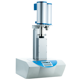
上海依阳实业有限公司为您提供《基于感应加热试样的高速激光干涉热膨胀仪》,该方案主要用于其他中检测,参考标准--,《基于感应加热试样的高速激光干涉热膨胀仪》用到的仪器有激光干涉法热膨胀测试系统
推荐专场

相关方案
更多
该厂商其他方案
更多