


方案详情
文
本文介绍了一种在室温附近测试各种量块和其它相似形状材料的高精度热膨胀系数测试仪器的研究开发。量块热膨胀所引起的长度变形通过一个差分平面镜干涉仪进行测量,采用特殊的干涉相位检测技术来补偿极化混合带来的非线性误差,再结合电子相位计可以实现纳米量级的精度。由于是在真空中进行量块热膨胀测量,从而无需进行空气折射率补偿。对于导热系数较高的被测试样,缓慢的辐射热交换使得试样上的温度梯度很小并具有很好的热平衡稳定性。在所获得典型的10~30℃温度之间热膨胀测试曲线,其线性和二次方热膨胀系数都等于在20℃参考温度时的热膨胀系数。本文对此激光干涉法热膨胀仪的测量不确定进行了详细分析,而且此测量不确定度也通过国际比对得到了验证。
方案详情

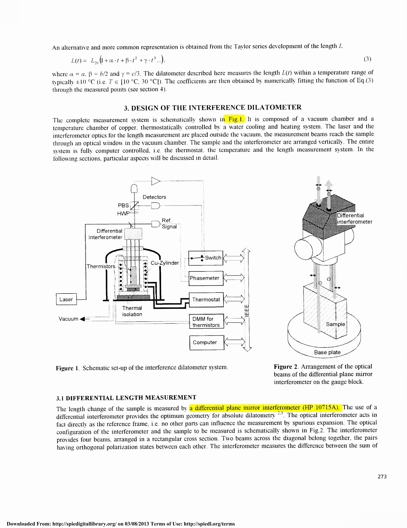
Thermal expansion measurement of gauge blocks Wen-Mei Hou , Rudolf ThalmannSwiss Federal Office of Metrology, CH-3003 Bern-Wabern, Switzerland ABSTRACT An instrument for the measurement of the thermal expansion coefficient near room temperature of gauge blocks and othersamples of similar shape and size has been developed. The length dilatation is measured by a differential plane mirrorinterferometer. A special interference phase detection technique compensates for non-linearity errors caused bypolarization mixing. In combination with an electronic phase meter this allows to achieve nanometer accuracy. Since themeasurements are done in vacuum, no compensation for the refractive index of air has to be made. For samples with goodthermal conductivity the slow heat exchange by thermal radiation allows for a small temperature gradient of the sampleand a good stability in the thermal equilibrium. From the thermal expansion curve, measured in a temperature rangetypically between 10 °C and 30 °C, the linear and quadratic expansion coefficients are evaluated at 20°C, the referencetemperature for length. It is shown, that for the investigated gauge block materials the room temperature expansion can bevery accurately described with two coefficients within a few parts in 10° per degree. A detailed analysis of themeasurement uncertainty demonstrates the capability of the measurement instrument, which is confirmed by the results ofan international comparison. Keywords: Thermal expansion coefficient, gauge block metrology, high-resolution interferometry 1.INTRODUCTION According to the international standard ISO 1, all length measurements have to be referred to the reference temperature20 °C. This means that for all precise dimensional measurements, corrections have to be applied, if the measurements arenot carried out at 20 °℃ exactly, taking into account the thermal expansion coefficient of the standards or workpieces to bemeasured. In gauge block metrology, the knowledge of the expansion coefficient is often an important component in theuncertainty budget. If, for example, a 100 mm gauge block is calibrated at a temperature deviating by 0.2℃ from 20°Cand the expansion coefficient is known from a manufacturer specification to be within an interval of±1·10C, thiswould contribute to the standard uncertainty by 0.012 um, which is almost comparable to the combined uncertaintiesstated by leading national metrology institutes for interferometric gauge block calibration. In order to reduce this uncertainty contribution, but also to investigate the thermal expansion of gauge blocks moregenerally and to provide thermal expansion measurements as a service for customers, a dilatometer for the accurateabsolute measurement of thermal expansion coefficient of gauge blocks and similarly shaped samples has been developed.The instrument works near room temperature, the length measurement is done by optical interferometry. 2. DEFINITION OF THE THERMAL EXPANSION COEFFICIENT The linear coefficient or of thermal expansion at the temperature T is defined as where L is the length of the specimen. Since the expansion is not linear, ar depends on the temperature of the material. Itis convenient to introduce a temperature scale offset by the reference temperature, i.e. t=T-20°C. The dependence ontemperature of a can be expressed by a polynomial' Present address: Physik Instrumente (PI) GmbH & Co,D-76337 Waldbronn, Germany " Tel: +41 31 323 33 85; Fax: +41 31 323 32 10; email: rudolf.thalmann@eam.admin.ch; http://www.ofmet.admin.ch/ Part of the SPIE Conferenceon Recent Developments in Optical Gauge Block Metrology An alternative and more common representation is obtained from the Taylor series development of the length L where a=a. =b/2 and y=c/3. The dilatometer described here measures the length L(t) within a temperature range oftypically+10C (i.e. T e[10C. 30°C]). The coefficients are then obtained by numerically fitting the function of Eq.(3)through the measured points (see section 4). 3. DESIGN OF THE INTERFERENCE DILATOMETER The complete measurement system is schematically shown in Fig.l.It is composed of a vacuum chamber and atemperature chamber of copper. thermostatically controlled by a water cooling and heating system. The laser and theinterferometer optics for the length measurement are placed outside the vacuum. the measurement beams reach the samplethrough an optical window in the vacuum chamber.The sample and the interferometer are arranged vertically. The entiresystem is fully computer controlled, i.e. the thermostat. the temperature and the length measurement system. In thefollowing sections, particular aspects will be discussed in detail. Figure 1. Schematic set-up of the interference dilatometer system. Figure 2. Arrangement of the opticalbeams of the differential plane mirrorinterferometer on the gauge block. 3.1 DIFFERENTIAL LENGTH MEASUREMENT The length change of the sample is measured bya differential plane mirror interferometer (HP 10715A). The use of adifferential interferometer provides the optimum geometry for absolute dilatometry . The optical interferometer acts infact directly as the reference frame, i.e. no other parts can influence the measurement by spurious expansion. The ' icalconfiguration of the interferometer and the sample to be measured is schematically shown in Fig.2. The interferometerprovides four beams, arranged in a rectangular cross section. Two beams across the diagonal belong together, the pairshaying orthogonal polarization states between each other. The interferometer measures the difference between the sum of the optical path lengths of each pair. The change of optical path length within the measurement volume due to any changeof the refractive index is completely eliminated by the fact, that the interferometer measures in vacuum. The onlyremaining influence which acts on the stability of the expansion measurement is the stability of the interferometer itself.This was measured to be below 2.5 nm/℃. Since the interferometer optics is situated outside the vacuum chamber andthe laboratory is temperature controlled, the long term stability of the interferometric length measurement is expected to bewithin an interval of±l nm. 3.2 HETERODYNE INTERFERENCE DETECTION The differential plane mirror interferometer used is a double-path polarizing interferometer and provides a sensitivity ofA/4= 157 nm for one interference fringe. The use of a Zeeman-stabilized HeNe-Laser with two orthogonally polarizedoptical frequencies allows for heterodyne detection at the beat frequency. The measurement of the interference phase withan electronic phase meter provides almost unlimited resolution. Dependent on the bandwidth of the detectors and thephase meter,rms phase noise below 1°, i.e. in the sub-nanometer region can easily be obtained. Limiting factor for the accuracy in heterodyne interferometry is the non-linearity produced by the polarization mixing orcross talk. This gives rise to periodic errors of about ±5 nm, dependent on the quality of the polarization optics, the lasersource and the alignment. By the application of an appropriate detection technique, polarization cross talk errors can besubstantially reduced. The principle of detection is shown in Fig.1. A polarizing beam splitter inserted in the output beamof the interferometer produces two interference signals with opposite phase (or opposite sign). It can be shown, that thedifference between these two signals is not affected by most of the polarization cross talk errors. Therefore, the interferencephase measurement is accomplished by measuring the phase of both signals in turn with respect to the reference signal andcalculating the average of the two. By this method, the interpolation linearity of the heterodyne interferometer can beimproved to deviations below l nm. 3.3 TEMPERATURE CHAMBER The chamber which accomodates the sample consists of a copper cylinder. A water helix in the cylinder wall connected toa thermostatic bath allows to change the temperature of the cylinder. The sample is placed in the center of the cylinder ona thermal isolation. The thermostatic cylinder is placed in a vacuum chamber in order to avoid the influence of airrefraction on the length measurement (change of the refractive index with pressure and strong turbulence during heatingor cooling). This means that the heat exchange between the sample and the cylinder is done only by radiation. Thetemperature uniformity of the sample depends on the temperature uniformity of the cylinder and the ratio between heatexchange by thermal radiation and the thermal conductivity of the sample material. Although the walls of the cylinder areuniformly tempered, the top and bottom cover of the cylinder, which follow passively, are also influenced by the walltemperature of the vacuum chamber, which is at room temperature. Temperature uniformity of the cylinder wall has beenfound to be within 20 mK, differences between top and bottom cover with respect to the wall temperature were alwayssmaller than 80 mK for a deviation from room temerature of about 10℃. On 100 mm gauge blocks maximumtemperature gradients of 35 mK, 45 mK, 120 mK and 150 mK have been measured for the different materials steel,tungsten carbide, aluminum oxide ceramic and zerodur, respectively. As long as these gradients are linear, the use of theaverage temperature for the determination of the thermal expansion coefficient will not lead to significant errors. Thecontributions due to residual temperature non-uniformity, which have to be taken into account for the measurementuncertainty evaluation, amount to 5 mK, 4 mK, 12 mK and 13 mK for the four different materials mentioned above. Thetemperature uniformity, but also the time constant for temperature changes (see section 4) could certainly be improved byintroducing a helium atmosphere - helium has excellent thermal conductivity- in the vacuum chamber at sufficiently lowpressure (~1 hPa), in order to keep the refractive index sufficiently low. 3.4 SAMPLE GEOMETRY As mentioned earlier, the instrument has been designed essentially for gauge blocks. These are wrung to a flat platen withthe upper measurement surface of the gauge block and the platen surface acting as mirrors for the differentialinterferometer (Fig.3a).Other samples than gauge blocks are possible, provided that they are sufficiently parallel (betterthan 0.3 mrad). If the end surfaces are polished, one of these can directly be used as a mirror, otherwise a small gaugeblock with known expansion coefficient can be fixed on top of the sample (Fig.3b). Also tube shaped samples can bemeasured. An assembly of three gauge blocks appropriately wrung together can be placed as top mirror withoutintroducing an additional thermal expansion (Fig.3c). The limit sample dimensions are: 130 mm for the length, 9 mm for the smaller width of a prismatic or the diameter of a cylindrical sample and 21 mm for the inner diameter of a tube shapedsample. Figure 3. Different possible sample geometries to be used with the four measurement beams of the differential inter-ferometer: (a) prismatic (gauge block), (b) cylindrical, (c) tube. 4. MEASUREMENT PROCEDURE For the expansion measurements, the temperature is changed typically in the range of 10 °C to 30 °C in steps of 3 °C to5℃. The measurements are performed at each point in a quasi-equilibrium, the difference between sample and thechamber temperature being smaller then 0.05 °C, which corresponds after a temperature change of a few degrees to aresidual rate ofabout 0.3 mK/min. Waiting for an equilibrium allows for a better temperature measurement accuracy and abetter uniformity of the sample temperature. The change of the chamber wall temperature by the circulating water is relatively fast (a few minutes). On a step likechange of the thermostat, the sample temperature follows an exponential function. The time constant depends on the absorption and the reflectivity of the sample surface for heatradiation and the heat capacity of the material. It has beenmeasured to be between 1% and 3 hours(Table 1).. Forachieving the quasi-equilibrium in each point, 4.6 times thetime constant has to be waited, which can be more than halfa day. A full cycle of expansion measurement lasts up tofour days. Although this might seem to be long, the systemis fully automatic and the long measurement time does notpresent any problem, if not a large series of samples has tobe measured. A controlled Helium atmosphere wouldprobably speed up the measurement process by a factor oftwo to three. t/°C AL(t) / um 8Ljin/ nm 8Lquad / nm 10.759 0 -20.4 -0.4 13.901 1.324 0.1 0.3 17.083 2.674 12.3 0.4 20.375 4.078 16.5 0.3 23.659 5.488 11.5 -0.6 26.848 6.865 -0.4 -0.4 0.4 Figure 4. Measured thermal expansion AL(t)=L(t)- L(t=10.759C) for a tungsten carbide gauge block and residuals 8L inmand 8Lquad from linear and quadratic fit with coefficients α=4.279.10caand α=4.27610-6°clp=0.0039.106℃, respectively. 5.UNCERTAINTY OF MEASUREMENT The uncertainty of measurement of the interference dilatometer shall be evaluated according to the ISO Guide’. Theestimation is made for 100 mm gauge blocks of different material, assuming a measurement cycle of 7 points regularlyspaced by 3.33°C ranging from 10 ℃ to 30 °C. The combined uncertainty is essentially determined by four contributions: uncertainty of the fit due to random uncertainties in temperature and length measurement; uuniformity of the temperature within the sample; calibration of the temperature sensors; drift in length measurement. Other contributions such as the uncertainty of the optical wavelength and of the absolute length of the sample or cosineerror are negligible. The square of the standard uncertainty of the linear thermal expansion coefficient is then given by 8a=CLft8L+ctir8t+cm8t+cr8t+cLa8L (4) where 8L, and 8t; are the standard uncertainties of the input quantities and c; the sensitivity coefficients. 5.1 UNCERTAINTY OF THE FIT (8L, 8t) The uncertainty of the fitted parameter caused by random variations of the input quantities has been numerically simulatedby introducing random errors in length and temperature to the least squares fit calculation. The following sensitivitycoefficients have been found: CLft=(1/L)3.210-2c-and ciit =o.310-2c- 5.2 TEMPERATURE UNIFORMITY (8t) The sample temperature uniformity is best near room temperature, whereas the largest temperature gradients are found athe extremes of the temperature range. From three temperature sensors fixed at the bottom, mid height and top of thesample, the maximum deviations of the average temperature obtained from the three readings from the real averagetemperature of the sample has been estimated to 7 mK, 5 mK, 17 mK and 20 mK for steel, tungsten carbide, ceramic andzerodur, respectively. The sensitivity coefficient is ctu=2o/AT, where AT=20C is the range of the temperature change 5.3 CALIBRATION OF THE TEMPERATURE SENSORS (8t) The temperature sensors (thermistors with 10 k nominal resistance at 25C) are calibrated with respect to a Pt25standard platinum resistance thermometer in the temperature range between 10 °C and 30 °C. The absolute value of thecalibration is only of second order importance, but the slope and the stability will have to be considered. This is estimatedto <10 mK for the full range including the drift since the last calibration, i.e. 8t=6 mK standard uncertainty with thesensitivity coefficient cte= a/AT. 5.4 STABILITY OF THE INTERFEROMETER (8La) The drift of the interferometer during the measurement cycle is estimated from the closing error (after a the fulltemperature range the temperature is set to the initial value and this last measurement point is compared to the fittedexpansion curve), which is usually a few nanometers and has never been larger than 6 nm after four days of measurement.A long term stability test obtained from an ,,expansion" measurement without sample resulted in a maximum drift value of1.6 nm. The sensitivity coefficient is CLd=1/(L.A7). 5.5 COMBINED STANDARD UNCERTAINTY The standard uncertainty for the linear expansion coefficient depends on the material (expansion coefficient, thermalconductivity) and the sample length. Based on the uncertainty contributions discussed above, the combined uncertainty iscalculated for four 100 mm gauge blocks of different material (table 2). For the examples given, the standard uncertainty isalways smaller than 10C. u(x;) Ci ui(y) u(x;) C; ui(y) Temperature, random Temperature uniformity Temperature calibration Length stability Length, random 3.6 nm 5·10/(mm℃) 1.7·10°c 1 nm 20 mK 0 06mK 0 0 3.6 nm 5.10/(mm℃) 1.710c 3.2·10"/(mm℃) 0.32·10C 1nm 3.210"/(mm℃) 0.3210℃ Temperature, random 1mK 0.34.10C² 0.34·10c 1mK 0.2810℃ 0.28·10°c Temperature uniformity 7mK 1.210-C 8.410c 5mK 0.94106C 410c Temperature calibration 6mK 2.4106c² 3.610c 6mK 1.88106℃² 2.810℃- Length stability 3.6 nm 5·10/(mm°C) 1.7·10°c 3.6 nm 5·10/(mm°C) 1.710c- Combined std. uncertainty 7.610c Combined std. uncertainty 1.7·10°c Table 2M.easurement uncertainty budget for four 100 mm gauge blocks of different material, i.e. steel, tungsten carbide,ceramic and zerodur. u(x;) are the standard uncertainties of the input quantities, c; the sensitivity coefficientsand u;(y)=u(x)c; the corresponding contributions to the combined uncertainty. 6.INTERNATIONAL COMPARISON In 1994, an interlaboratory comparison of measurements of the thermal expansion coefficient has been carried out. Sevenlaboratories of five European national metrology institutes took part with the Swiss Federal Office of Metrology (OFMET)as the pilot laboratory. The linear thermal expansion coefficient at room temperature (20°C) of four 100 mm gauge blocksof different material had to be measured. Various types of instruments were used for the measurements. Common to all but one instrument was the interferometriclength measurement. Some laboratories carried out their measurements on their usual absolute gauge block interferometer(NMI/VSL, PTB1, IMGC), changing the temperature of the gauge blocks by a thermostatic cooler / heater or by thelaboratory temperature. Others have developed dedicated instruments for thermal expansion measurement, exclusively forgauge blocks (NPL, OFMET) or for more general, larger specimens (PTB3).PTB2 used a mechanical comparator andthermal expansion standards calibrated by PTB1. The measurement results in units of 10Ctogether with the associated uncertainties are shown in Fig.5. The agreementexpressed as the difference between the largest and the smallest value was 0.0810-6c-for steel, 0.075.106c-fortungsten carbide, 0.17.106cfor ceramic, and 0.0710°Cfor zerodur. Figure 5. Results of the European interlaboratory comparison of thermal expansion measurements of four 100 mm gaugeblocks. The results are expressed in 10. 7.REFERENCES 1.S.J. Bennett, ,,An absolute interferometric dilatometer", J. Phys. E: Sci. Instrum. 10, pp. 525-530, 1977. 2. K. P. Birch, “An automatic absolute interference dilatometer", J. Phys. E: Sci. Instrum. 20, pp. 1387-1392, 1987 3. M. Okaji and H. Imai,“A high-temperature dilatometer using optical heterodyne interferometry”, J. Phys. E: Sci.Instrum. 20, pp. 887-891, 1987. 4W. Hou and R. Thalmann, “Accurate measurement of the refractive index of air", Measurement 13,pp. 307-314,1994. 5.1.R. Thalmann and W. Hou,“Limitations of interpolation accuracy in heterodyne interferometry”, in InternationalProgress in Precision Engineering, N. Ikawa et al. Eds., Proceeding of the 7h international precision engineeringseminar, Kobe, Japan, 1993. 6.W. Hou and G. Wilkening,“Investigation and compensation of the non-linearity of heterodyne interferometers”, Prec.Eng.14, pp. 91-98,1992. 7.Guide to the expression ofuncertainty in measurement, Geneva, International Organization for Standardization, 1993. 8.R. Thalmann, International Comparison, Final Report, Metrologia 33, pp. 187-188, 1996. an Diego,California·July PIE Vol./$ownloaded From: http://spiedigitallibrary.org/ on Terms of Use: http://spiedl.org/terms
确定


还剩5页未读,是否继续阅读?

产品配置单
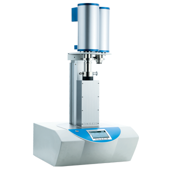
上海依阳实业有限公司为您提供《采用激光干涉法测试量块的热膨胀系数》,该方案主要用于其他中检测,参考标准--,《采用激光干涉法测试量块的热膨胀系数》用到的仪器有激光干涉法热膨胀测试系统
推荐专场
相关方案
更多
该厂商其他方案
更多