


采用LaVision的ImagerIntense型CCD相机和Quantel公司的Twins型PIV双脉冲激光器对钝体燃烧器湍流流场进行了测量和分析。
方案详情

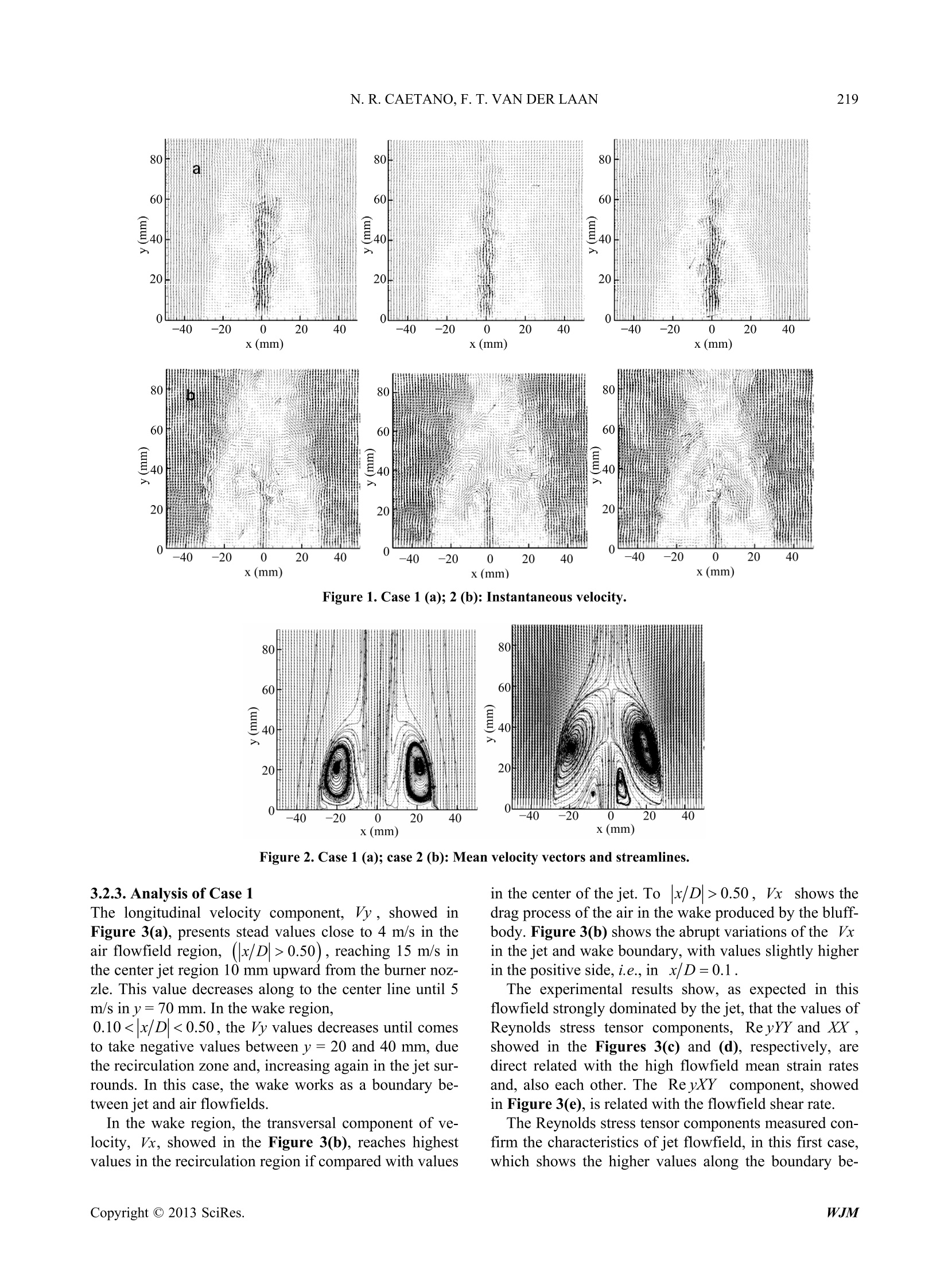
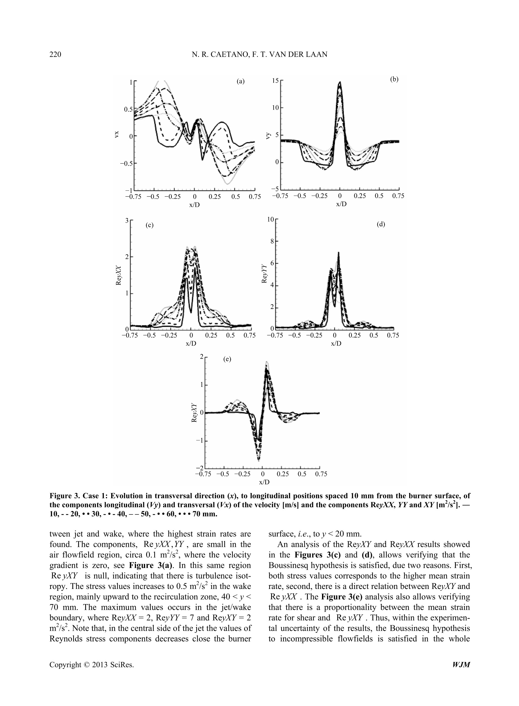
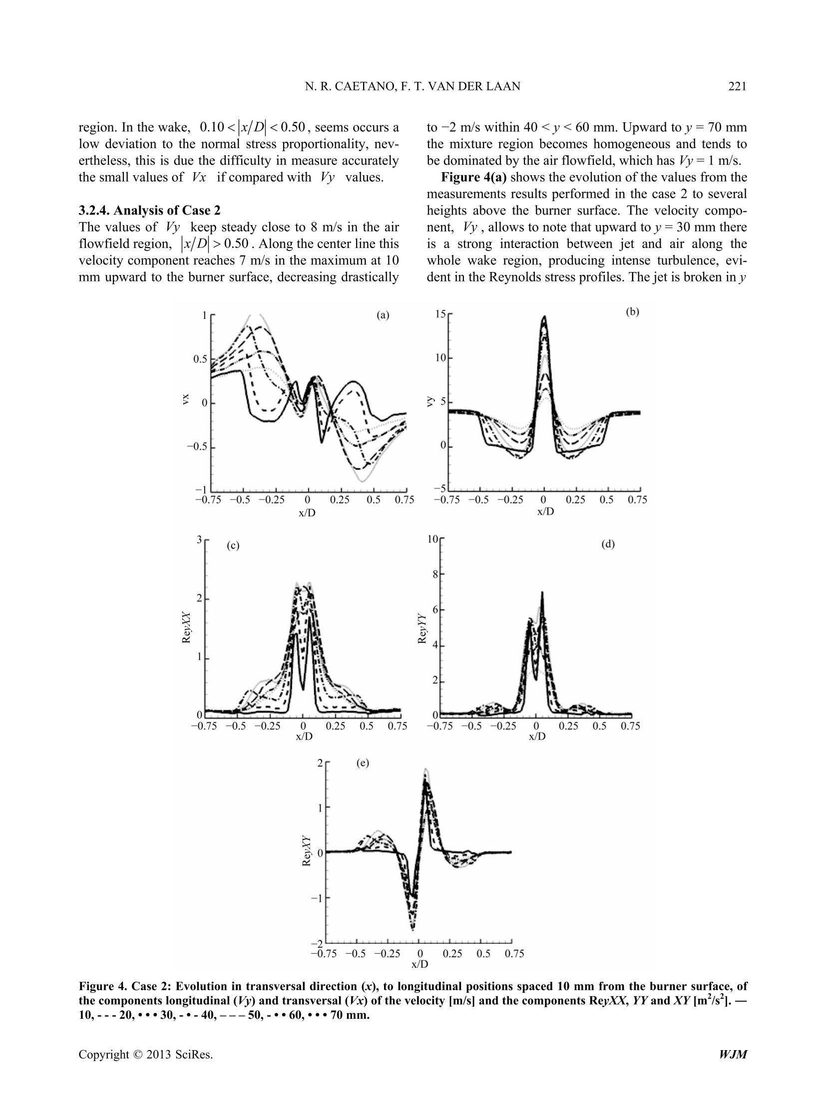
World Journal of Mechanics, 2013, 3, 215-223doi:10.4236/wjm.2013.34021 Published Online July 2013 (http://www.scirp.org/journal/wjm) 216N. R. CAETANO, F. T. VAN DER LAAN Turbulent Flowfield Analysis in a Bluff-Body BurnerUsing PIV Nattan Roberto Caetano, Flavio Tadeu van der Laan Department of Mechanical Engineering, University Federal of Rio Grande do Sul, Porto Alegre, BrazilEmail: nattan@ufrgs.br Received November 29, 2012; revised January 15, 2013; accepted January 23, 2013 Copyright C 2013 Nattan Roberto Caetano, Flavio Tadeu van der Laan. This is an open access article distributed under the CreativeCommons Attribution License, which permits unrestricted use, distribution, and reproduction in any medium, provided the originalwork is properly cited. ABSTRACT The structure of inert turbulent flows, stabilized in a Bluff-Body burner, is studied considering different volumetricflows for Nitrogen jet and annular air in coflow configuration. Flowfield analysis on Bluff-Body burner is essential toimprove the knowledge about this burner, which plays an important role in industrial applications. Thus, vector velocityfield is performed, employing Particle Image Velocimetry technique. Also, an uncertainty analysis is performed consid-ering parameters involved in this technique yielding 6% to velocity measurements. The acquired information producesthe results based in flowfield structure, which are presented in terms of statistical momentum and Reynolds stress, inwhich Boussinesq Hypothesis is considered to incompressible flows. However, this hypothesis fails in certain condi-tions. In this way, is possible to comprehend and provide experimental data from the turbulent effects on the flowfieldand also contribute to predict the combustion flows, in order to enable the validation and develop numerical modelsS. Keywords: Particle Image Velocimetry; Turbulent Flowfield; Experimental Uncertainty; Boussinesq Hypothesis 1.Introduction The aim of the work is study, experimentally, turbulentflowfields stabilized on the Bluff-Body burner. Therefore,measurements are performed using non-intrusive opticaltechnique in order to yield the velocity field, employingPIV. This work intends to produce results which willallow apply advanced post-processing methods. So that,main experimental results are presented in order to verifythe flowfield structures characteristics, based in Boussi-nesq Hypothesis. The knowledge yielded constitutes adata base which enable developing and validation of nu-merical models. The present work emphasis is given by using the tech-nique which allows measure the turbulent flowfield pro-perties. Moreover, relevant aspects are approached, dataand statistical results processing. Velocity measurementsare necessary to investigate the turbulent flowfield struc-ture and flow stabilization. However, this work focus onthe analysis of the flowfield dynamic influence on theturbulence using velocity measures via Particle ImageVelocimetry PIV [1,2]. Measurements of vector velocityfield allow to perform the flowfield characterization bythe analysis of the results from statistical momentum, aswell as, through the flowfield Reynolds stresses tensor. The flowfield stability depends on the interactions be-tween dynamic, mixture and, chemical of the fluids con-sidered. In this way, the velocity field structure plays animportant role on the numerical models development.However, is a determinant factor in works which intendto characterize the different flowfield structures. Thus.both the diagnostic method purposed, followed by animage post-processing, enriched the range of statisticalinformation available. such as a contribution toward theinformation database creation, which allows comparisonsand numerical models calibration [3]. About parameters ofthe measure technique applied inturbulent flowfield based on lasers, a trend is observed.The capture rate used to measure reaching about kHz, inone plane [4]. These measures covered small interroga-tions areas, about some mm , due the lasers energy limi-tations. The size of the measurement window is smallerthan the normal techniques are able to capture, circa 100cm’. Nowadays, the works perform 3D vector field ve-locity,which is measured simultaneously with one scalar,more often, OH or CH, or temperature [5,6]. High speedequipment is employed in order to investigate turbulenteffects using information taken in high temporal resolu-tion, in one or more planes [7]. Therefore, the results are described in terms of two first statistical momentumsfrom the aero-thermochemical measures, as well as, ad-vanced post-processing concerning the probability den-sity function evolution and its derivatives, as vorticity orstrain and stress rates [8]. 2. Experimental Approach 2.1. Burner Configuration The Bluff-Body burner used in this work was designedfor the purpose of cover a broad operation range [9]. Thistype of burner is relevant in several engineer applications,including industrial flowfield problems, because is ableto stabilize flames in different combustion regimes on itswake zone. This burner allows details studies about inter-action between turbulence and chemical kinetic by usingoptical measuring techniques due the broad access, more-over, the high symmetry and simple boundary conditionsbecame easy the numeric solutions algorithm. The burnerdimensions was choose in order to obtain a large differ-ence between thickness of laser light plane and jet di-ameter, 0.5 and 7.1 mm, respectively. The fuel supplychannel have 150 cm, ensuring the fully flowfield de-velopment. The wind tunnel is 200 mm from which theenvironment air flowfield exits surrounding the centralbluff-body with 60 mm diameter. The duct length is 1 m,up a turbulence generator grid, which has 12 mm of di-ameter holes, separated 10 mm each other to generateturbulence, used in order to homogenize the flowfield.The interrogation window size is 120 ×90 mm’upwardto the burner surface, which is centered in the fuel jet.Thus, this burner produces a turbulent flowfield contain-ing a concentric central jet to an annular air exit aroundof the central body. To provide the air a fun (Deltra, VC-400) is used, which yield up to 10 m/s at the maximumfrequency rotation, 60 Hz. The top boundary of the flow-meter (OMEL, 3P5-0401V01) is 3 Nm/h. Thus, the maxi-mum fuel velocity is about 30 m/s in standard tempera-ture and pressure conditions. 2.2. PIV Technique A double pulse Nd:YAG laser (Quantel, Twins) is usedas source to illuminate the particles seeded in the flow-field by a laser light sheet of 532 nm and 0.5 mm ofthickness. The cavities of laser are independent, allowinginput a time interval (dt) between two shoots. A camera(LaVision, Image Intense) captures the Mie scattering oflaser light from the particles on a 1376×1040 pixel ma-trix, of 12 bit, with 6.45 um pixel size and 70%of quan-tum efficiency close of 532 nm wavelength, yielding 4kbits of gray level contrast. Scattered photons are trans-mitted by a band-pass filter, centered in 532 ±5 nm,which are focused on the CCD sensor by a lenses ensem-ble (Nikon,Nikkop, f/1.4, 50 mm). Tracer particles seeded in flowfield in order to applyPIV should attend three fundamental requirements. First,particles should have minimum dimensions to be able toscatter the incident laser light. Second, particles shouldfollow the flowfield turbulent buoyancies. Third, parti-cles should have melting point above the flowfield tem-perature [10]. The accuracy in the determination of thetracer particles dimensions plays an important role in themeasurements uncertainty calculus in PIV [11]. PIV ap-plications in gas phase flowfields require smaller parti-cles and light power enough in order to the scattering in-tensity sensitizing the CCD camera, so that, the signal/noise relation is sufficient to produces quality images.These requirements are crucial to the PIV employmenthigh interference cases. The compromise between parti-cle size and light scattered intensity was valued, leadingthe choice of Titanium Dioxide (T;O2) particles, with 1um diameter, which are often used and recommended forthis purpose by the literature [2,11,12]. The density of particles should be selected toward en-sure the velocity measures within the expected range.Thus, both, the dimension and the density of the tracerparticles have direct influence on the measurements un-certainty. In particular, the relaxation time of the parti-cles when submitted to the flowfield velocity buoyanciesshould be smaller than the characteristic buoyancy time.Tracer particles dimension choice is the main parameterto the particles follow correctly the flowfield buoyancies.The relaxation time, t, is a convenient amount towardestimate the trend that particles have to keep in equilib-rium within the flowfield. The ideal particle size can beestimated from the relaxation time of a particle in a fluid,which is obtained from the Stokes equation [1], where dp=1 um is the mean particles diameter, u=17x 10 Pa. s is the kinematic viscosity of the air andp, =4.230kg/m’ is the specific mass of the TiO, theparticle material.However, this time is about 14 us, i.e.,the particles are able to follow buoyancies in the flow-field of about 70 kHz, regarding the conditions used inthis work. The velocity vector field is calculated by processingthe pairs of particle images. In this work 1000 pairs of 4Mb images was taken, in 3 Hz of acquisition rate. Thiscadence is not enough to describe the turbulent fluctua-tions of the flowfield, but is a limitation of the PIV sys-tem hardware. The processing is done by a dual core PCtakes about 7 hours in multi-pass mode, two passes; de-creasing window, 64× 64 to 32×32 pixels; and overlapof 50% and 75%, respectively to each pass, also applyingthe Whittaker reconstruction method [13,14]. These con-ditions were chose because yield better correlations and spatial resolutions, producing 5590 vectors spaced out1.5 mm. 2.3. Calibration of the Technique The commercial software LaVision DaVis recognizes thepattern of points in a special plate designed as a calibra-tion target, using an algorithm of search and recognizing.After that, a grid of known dimensions appears over theimage in order to attribute dimensions to the pixels. Theconfiguration set for this work the mean pixel diameter is90 um, with 0.5% of uncertainty. A TSI, APS 3320 Particle Sizer equipment was used tomeasure the particles dimension and concentration in theflowfield. The suitable amount of particles to the experi-ment was determined by the direct visualization of theparticle distribution in the Mie scattering images. The re-sults to both, jet and annular flowfields, are 1 um of par-ticles diameter with a low dispersion (o=0.3). A Dwyer, S471 DTA hotwire anemometer, 2.5% ofuncertainty, calibrated by Skilltech, was used to measurethe velocity of the annulus air in the burner flowfield.The results were compared with the PIV results in orderto verify the accuracy level. The measurements were ta-ken in two positions up wise of the burner surface, at theedge of the bluff-body and 100 mm higher, yielding 8.0and 7.8 m/s, respectively. The averages of the velocitiesmeasured by PIV in these positions are exactly the same,within the equipment uncertainty. 2.4. Measurement Uncertainty The uncertainty in PIV measurements involves topicswhich affect the accuracy, as the sources related andbriefly discussed in sequence, 1) refraction index gradi-ents,2) non-homogeneity in particle distributions, 3) par-ticle image size and, 4) information processing. The ma-ximum differences in the refractions index by the air andNitrogen is about 1%, as the thickness of the laser lightsheet, about 500 um, is 5 times higher than the pixel size,the maximum distortion yielded by the refraction indexgradients, uyn, is 2%. The non-homogeneity in particle distributions, due thedifference between gases density and viscosity, producesfails in the correlation maps, causing errors in the proc-essing and, consequently, yielding spurious vectors. Theuncertainty associated to the particle dispersion fails, ue,is higher in the wake region, as expected, because is therecirculation zone. The particle concentration in the wakeregion is 3%, maximum, lower than the jet and annularregions yielding an uncertainty of the same order ofmagnitude. The contribution of the particle image size can influ-ence to the uncertainty in PIV measurements in two as-pects. First, regarding the fidelity in follow the flowfield buoyancies. Second, is about the images processing,which correlation depends on the particle image dimen-sions in the frames and of the respective displacements.A study about the particle displacements was performedapplying numerical simulations [1], in order to evaluatethe influence. Regarding the configuration used to per-form the present work, comparing with the results achi-eved by the simulations in the literature, the ideal size ofthe particle image is 1.5 pixel. The beam steering is alsoan important factor in the signal to noise ratio. The win-dow size has similar importance because the uncertaintyincreases to smaller windows. The particle image diame-ter, d, is determined by, where dag=2.44f#(M+1)a is the minimum diame-ter of the light diffracted by particles, J#=11 is theratio between focal length and aperture diameter of thelenses in a camera, a=532 nm is the laser light wave-length and M= 0.10 is the image magnification. Theeffective diameter, 1 um, of the particles used in thiswork was measured using TSI Particle Sizer equipment.Therefore, the mean particle image diameter has 4 pixels,yielding an uncertainty of about 0.1 pixel, i.e., ua=±3% to processing windows of 32×32 pixels. The uncertainty brought by the information processingdepends on the several sources, the correlation betweenimage objects in the frames and the subpixel adjustment.The dispersion of the results around the maximum pointsin the correlation maps, calculated by the software, LaV-ision DaVis, is 3 pixels in the wake regions, where thecorrelation is weak. Thus, is possible to estimate a maxi-mum uncertainty due the correlation process as ucorrr=5%. The value of the error due the subpixel adjustmentachieved by simulations reaches Usp=3%[1]. These sources of uncertainty in the PIV technique wasdetailed analyzed [2], whereas the maximum total uncer-tainty, i.e. in the recirculation zone, is calculated usingthe Kline-McClintock method [15,16], considering thecontribution of each source discussed before. These re-sults were propagated toward achieve the total measure-ment uncertainty, as shown in the following Equations (3)and (4) (4) 3.Results In this section are presented: 1) the experimental results obtained by this work, 2) the analysis of the velocity re-sults yielded by PIV in order to characterize the flow-field dynamic structure produced in a Bluff-body burner.Thus, the jet Nitrogen and annular air flow conditions arerelated in the Table 1 for the two cases involved in thiswork. The mean jet velocity value is also introduced, inorder to improve the analysis. Also, the time intervalsbetween frames in PIV are presented for each case. Each studied case presented in this section involvesthree instantaneous overlapped by the respective vectorvelocity field, obtained on the burner symmetry plane.The behavior of the mean flowfield shown by streamlines is analyzed in the sequence, both obtained from1000 instantaneous images. Moreover, are discussed thebehavior of the mean velocity components, transversaland longitudinal, and the Reynolds tensor based in theBoussinesq hypothesis principle. These quantitative re-sults are presented in form of graphics where the valueswas extract from 7 transversal positions in 10 mm of in-terval between each other upward of the burner surface. 3.1. Boussinesq Hypothesis Analysis Turbulence modeling, generally, employs the Boussinesqhypothesis in order to determine the Reynolds tensor,through the relation with the mean strain rate in the flow-field as follow [17], where v, iis the turbulent viscosity, K=1/2|VVi1S the turbulent kinetic energy,8 is the Kronecker’s deltaand S, is the mean strain rate tensor. This tensor can besimplified to the flowfields which has revolution sym-metry, as the flowfield produced by the burner consid-ered, which implies that, if Boussinesq hypothesis is valid, v and 2 are proportional. Th termis re-lated to the density variations in combustion mixtures. Inthe figures of this section the notation used is Vx=V, ReyxY=V. The flowfield structure of two cases using Nitrogen inthe center jet was approached in order to analyze the be-havior of the turbulent properties. These cases, presented Table 1. Parameters of flowfield for cases considered. Case Gas Jet flow Jet vel. (m/s) Jet Reynolds number Air Vel. dt (Nm’/h) (m/s) (us) 1 N2 1.90±0.15 13.30±0.90 6066±425 4.00±0.01 27 2 N2 0.60±0.05 4.20±0.25 1915±135 8.00±0.0245 as 1 and 2 in Table 1, was choose to represent differentsituations on the recirculation zone. First case, has thefuel quantity of movement three times higher than thecase 2, whereas the flowfield is dominated by the jet. Inother hand, in the second case occurs the air advantage,in relation of the case 1. 3.2. Analysis of the Cases The flowfield structure oftwo cases using Nitrogen inthe center jet was approached in order to analyze the be-havior of the turbulent properties. These cases, presentedas 1 and 2 in Table 1, was choose to represent differentsituations on the recirculation zone. First case, has thefuel quantity of movement three times higher than thecase 2, whereas the flowfield is dominated by the jet. Inother hand, in the second case occurs the air advantage,in relation of the case 1. 3.2.1. Instantaneous Flowfield Analysis Figure 1(a) shows the vector velocity field of the case 1flowfield. Three instantaneous images of the velocitydistribution are presented, where the center jet blows outthe wake region. The quantity of movement of the jet ispractically the double of the air flowfield leading thesecharacteristics, which also confirm high symmetry of theflowfield. Figure 1(b) shows the behavior of the velocity flow-field to the case 2. The instantaneous measures intro-duces the low fluctuation of the air flowfield region andin the jet downward of y=20 mm from which the jetdisappear. This behavior is due the quantity of movementin the jet be smaller than in the air flowfield, if comparedto the case 1. 3.2.2. Mean Flowfield Analysis Figure 2 show the mean velocity flowfield distributionoverlapped by the streamlines. In Figure 2(a), the centerjet is predominant by the whole longitudinal direction ofthe measurement window, creating a toroidal vortex cen-tered in y=20 mm, upward this there is a compressionzone in the flowfield. In the mean flowfield of the case 2, showed in the Fig-ure 2(b), toroidal recirculation zones are found, whichproduce two stagnation points, along of the x/D=0.The streamlines draft these points, in the symmetry axis,between 30 and 60 mm upward of the burner surface.Thus, two recirculation zones can be seem, first, has asmaller diameter than the second and is placed in thevicinity of the jet, y= 10 mm, in the boundary betweenjet and wake. Second, centered in y =30 mm occupiesthe whole wake in the transversal direction. In this casethe flowfield is dominated by the wake, differently of thecase 1, which has the center jet predominant. Figure 1. Case 1 (a); 2 (b): Instantaneous velocity. Figure 2. Case 1 (a); case 2 (b): Mean velocity vectors and streamlines. 3.2.3. Analysis of Case 1 The longitudinal velocity component, Vy, showed inFigure 3(a), presents stead values close to 4 m/s in theair flowfield region,,(x/D|>0.50), reaching 15 m/s inthe center jet region 10 mm upward from the burner noz-zle. This value decreases along to the center line until 5m/s in y=70 mm. In the wake region, 0.100.50, Vx shows thedrag process of the air in the wake produced by the bluff-body. Figure 3(b) shows the abrupt variations of the Vxin the jet and wake boundary, with values slightly higherin the positive side, i.e., in x/D=0.1. The experimental results show, as expected in thisflowfield strongly dominated by the jet, that the values ofReynolds stress tensor components, ReyYY and XX ,showed in the Figures 3(C) and (d), respectively, aredirect related with the high flowfield mean strain ratesand, also each other. The ReyxY component, showedin Figure 3(e), is related with the flowfield shear rate. The Reynolds stress tensor components measured con-firm the characteristics of jet flowfield, in this first case,which shows the higher values along the boundary be- (a) 15r (b) -2儿L J -0.75-0.5-0.25 0 0.25 0.5 0.75 x/D Figure 3. Case 1: Evolution in transversal direction (x), to longitudinal positions spaced 10 mm from the burner surface, ofthe components longitudinal (Vy) and transversal(Vx) of the velocity [m/s] and the components ReyXX, YY and XY [m /s]. -10,--20,··30,-·-40,--50,-··60,···70 mm. tween jet and wake, where the highest strain rates arefound. The components, Re yXX,YY, are small in theair flowfield region, circa 0.1 m/s, where the velocitygradient is zero, see Figure 3(a). In this same regionReyXKYY iiss null, indicating that there is turbulence isot-ropy. The stress values increases to 0.5 m’/s’in the wakeregion, mainly upward to the recirculation zone,400.50. Along the center line thisvelocity component reaches 7 m/s in the maximum at 10mm upward to the burner surface, decreasing drastically to -2 m/s within 40
确定
还剩7页未读,是否继续阅读?

产品配置单


北京欧兰科技发展有限公司为您提供《钝体燃烧器中速度场检测方案(粒子图像测速)》,该方案主要用于其他中速度场检测,参考标准--,《钝体燃烧器中速度场检测方案(粒子图像测速)》用到的仪器有德国LaVision PIV/PLIF粒子成像测速场仪、LaVision DaVis 智能成像软件平台
推荐专场


相关方案
更多
该厂商其他方案
更多