


方案详情
文
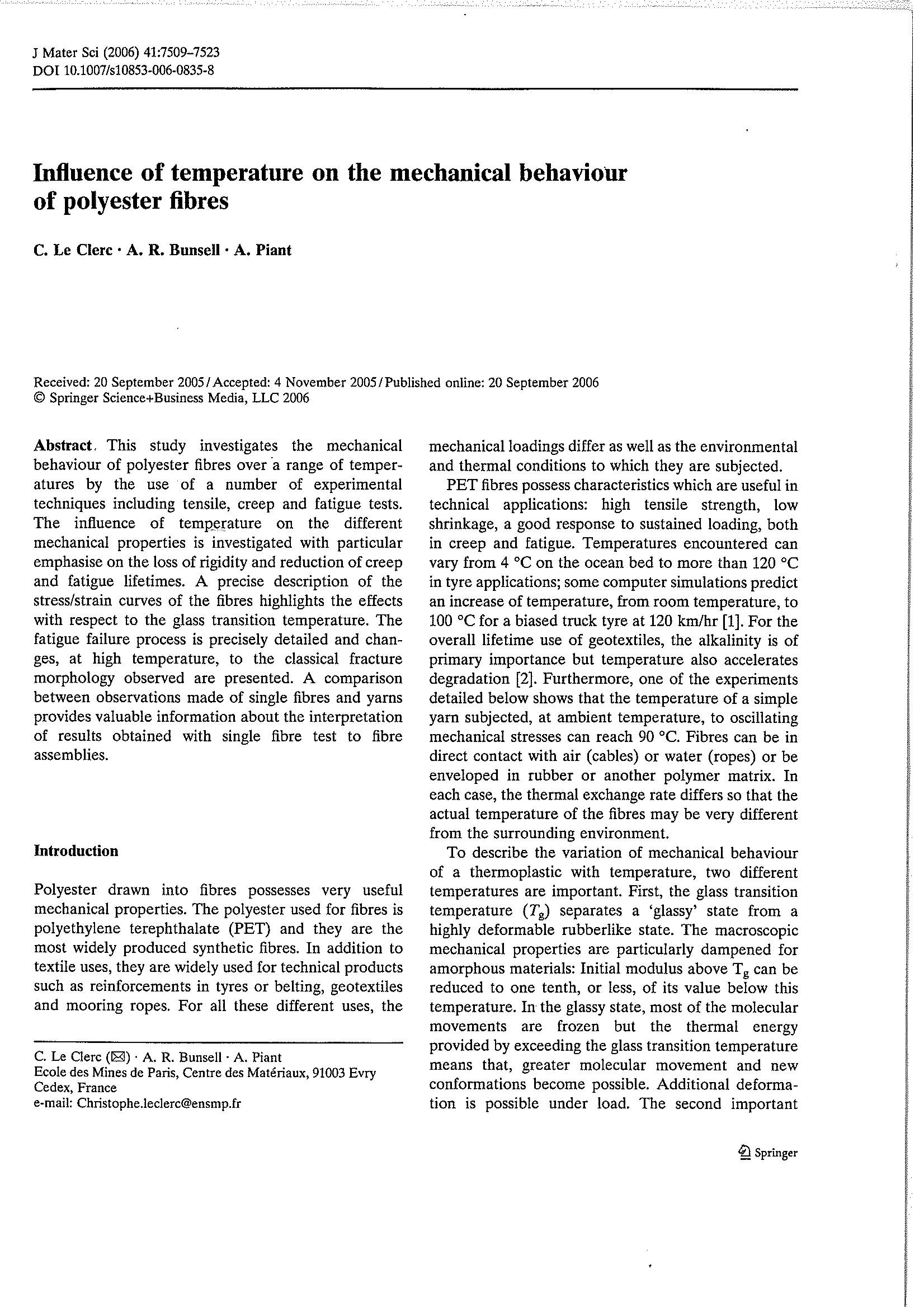
this study investigates the mechanical behaviour of polyester fibres over a range of temperatures by the use of a number of experimental techniques including tensile, creep and fatigue tests.the influences of temperature on the different mechanical properties is investigated with particular emphasise on the loss of rigidity and reduction of creep and fatigue lifetimes.A precise description of the stress /strain curves of the fibres highlights the effects with respect to the glass transition temperature. The fatigue failure process is precisely detailed and changes, at high temperatures, to the classical fracture morphology observations made of single fibres and yarns provides valuable information about the interpretation of result obtained with single fibre test to fibre assemblies
方案详情

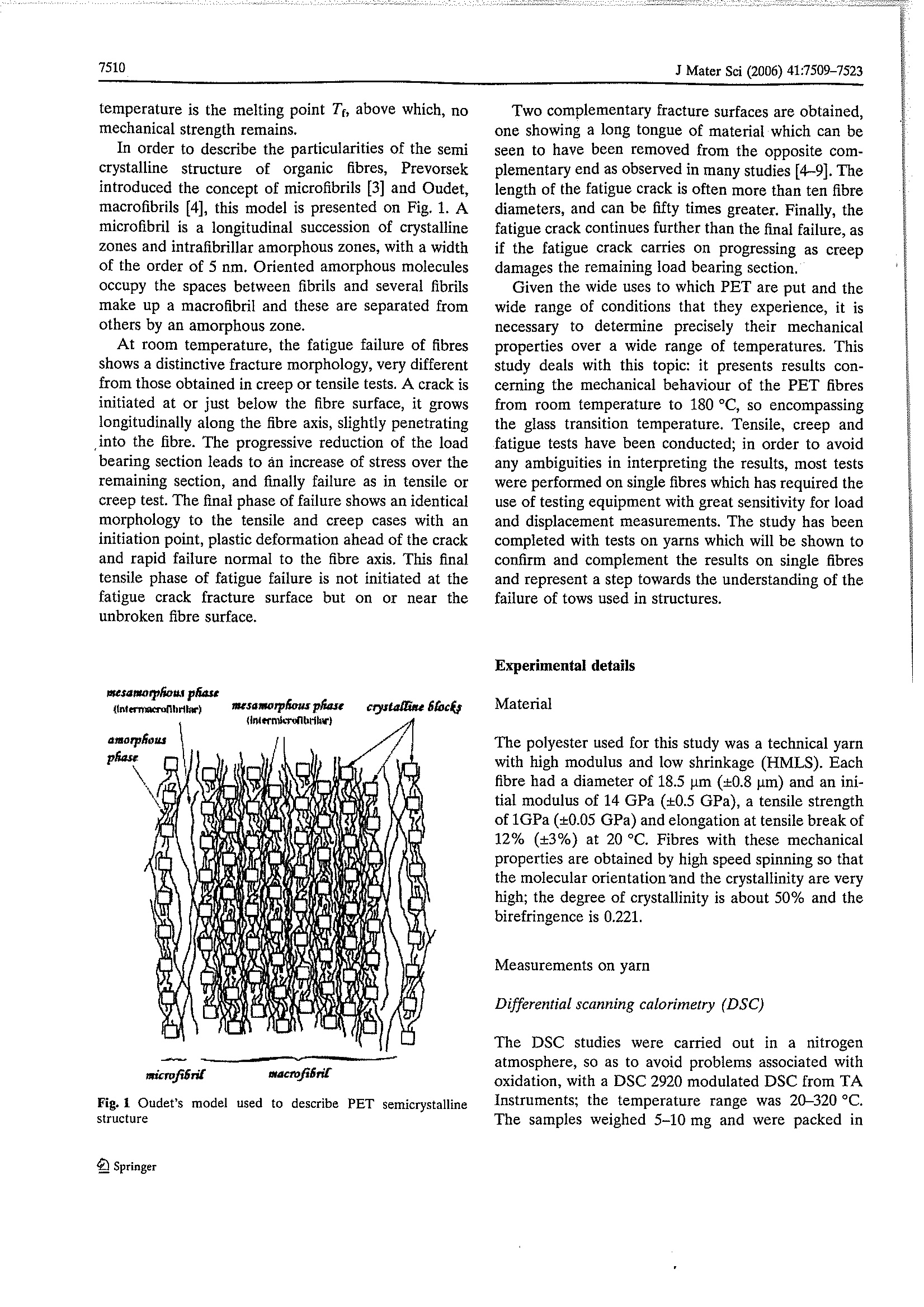
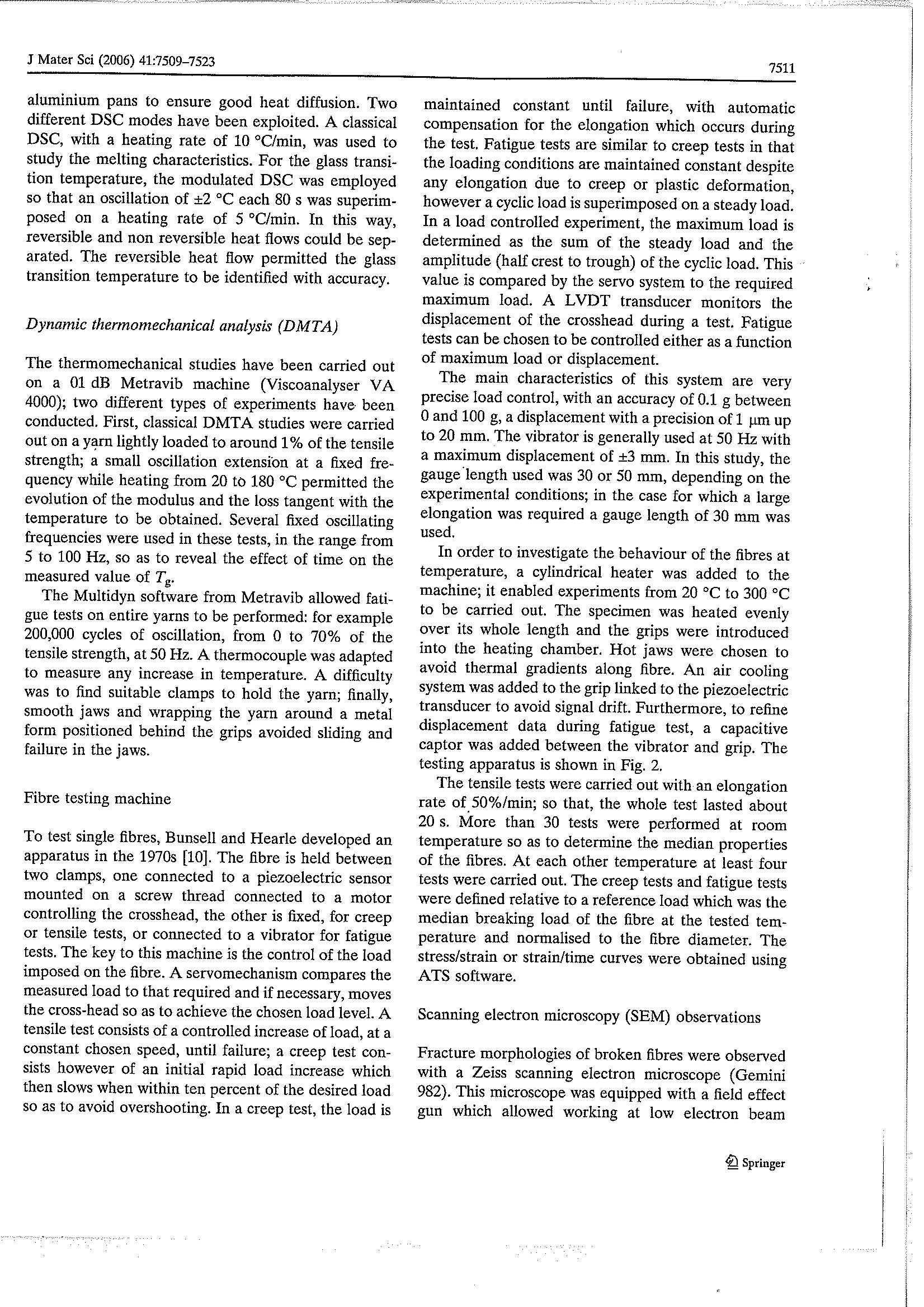
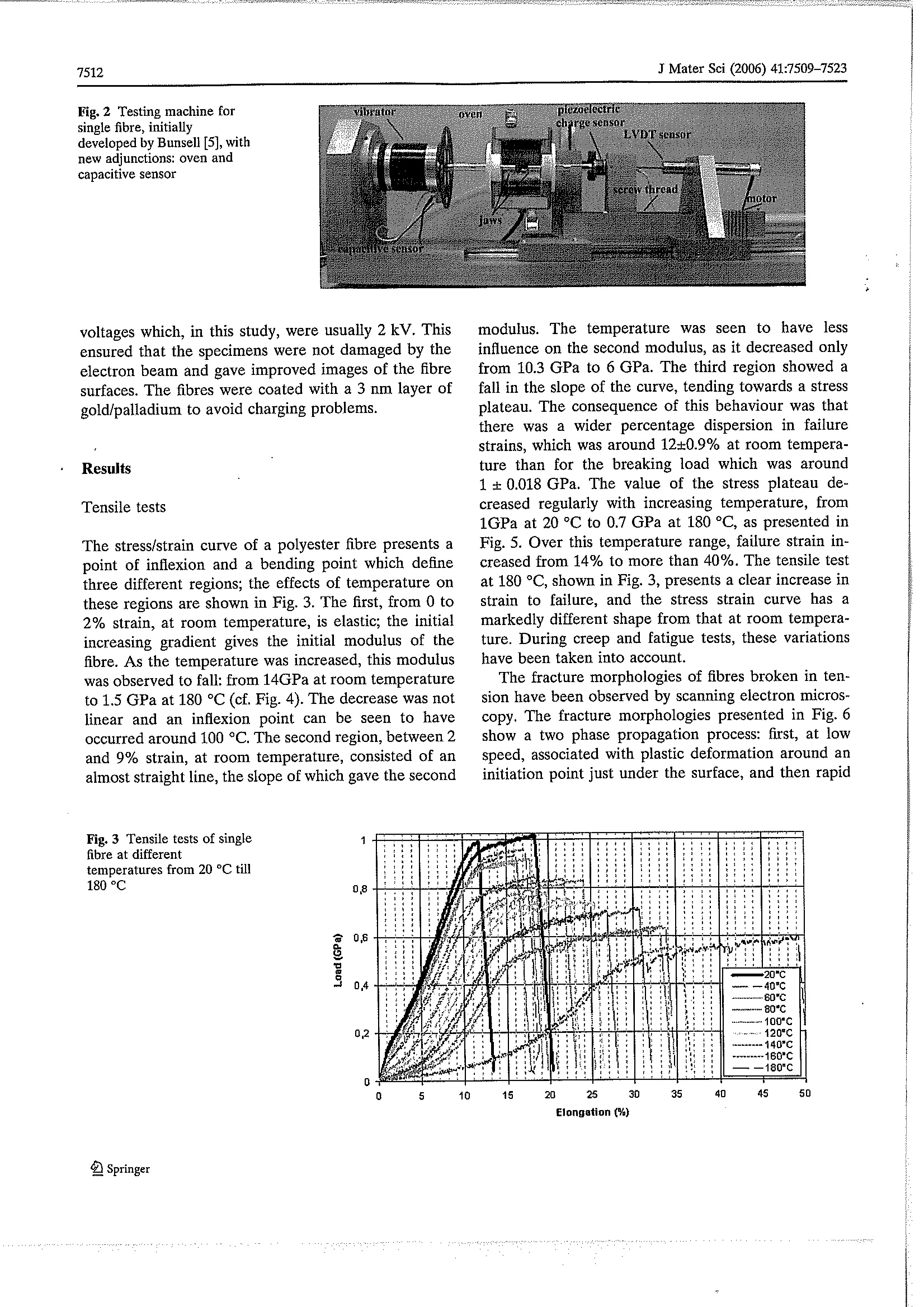
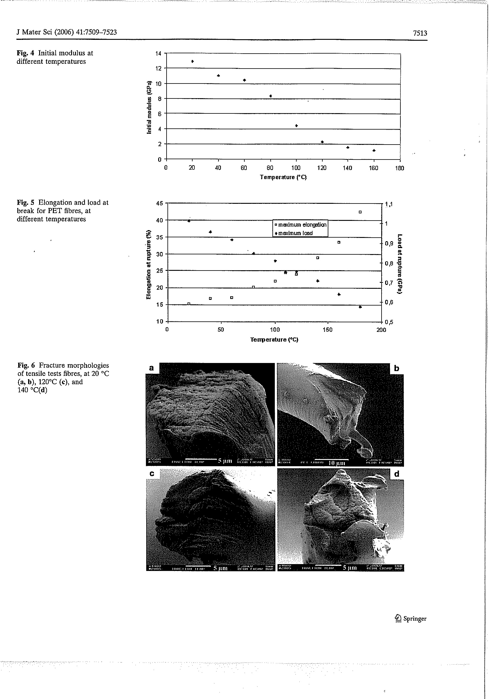
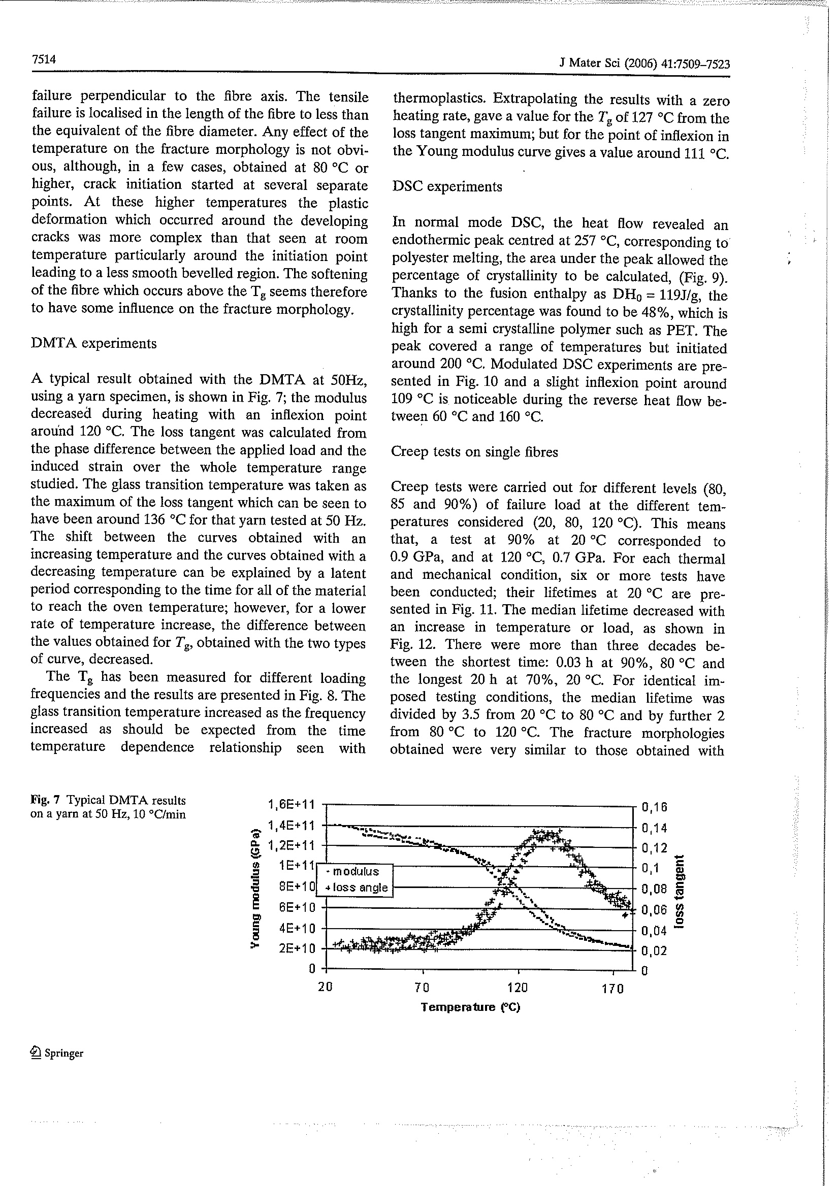
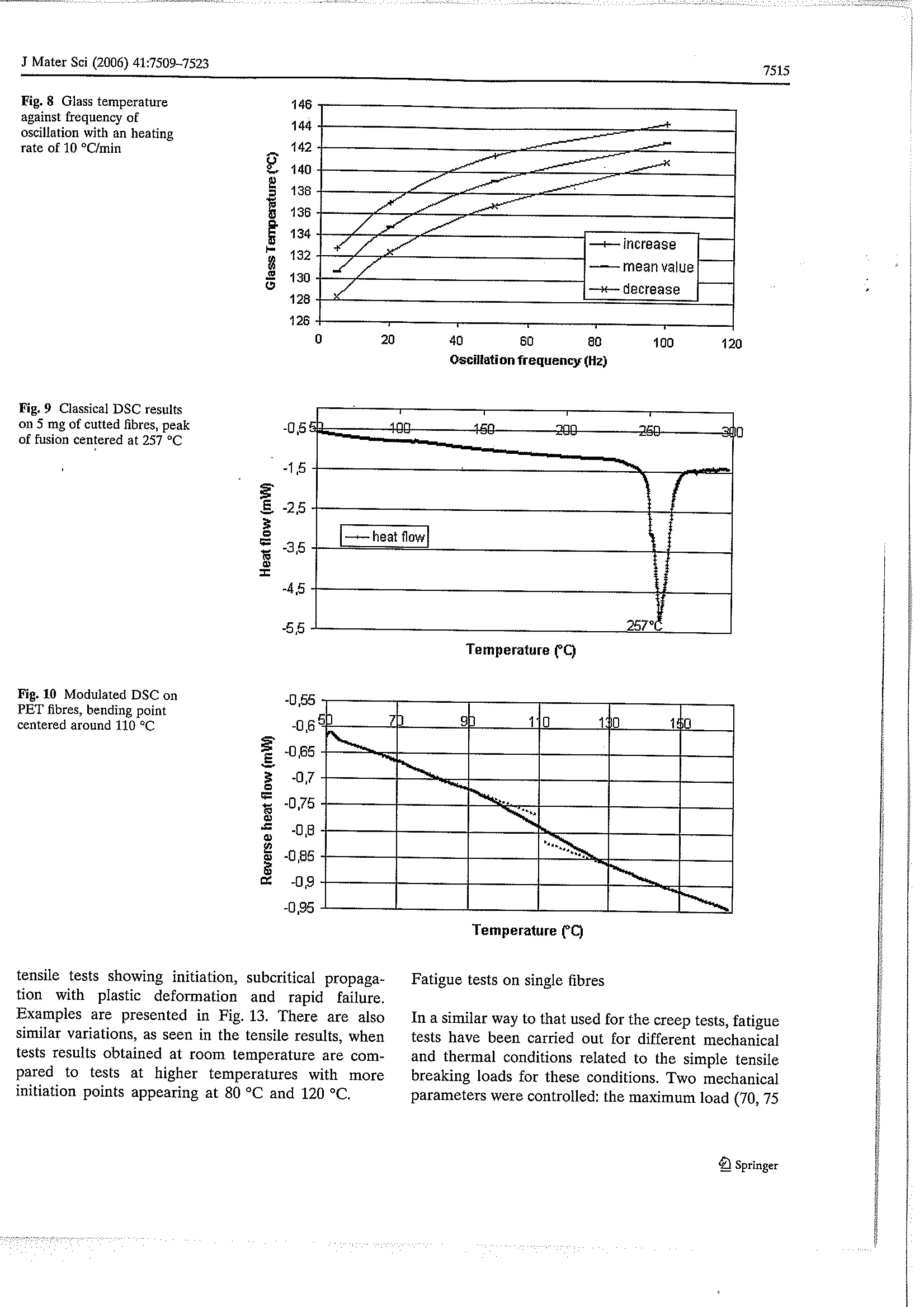
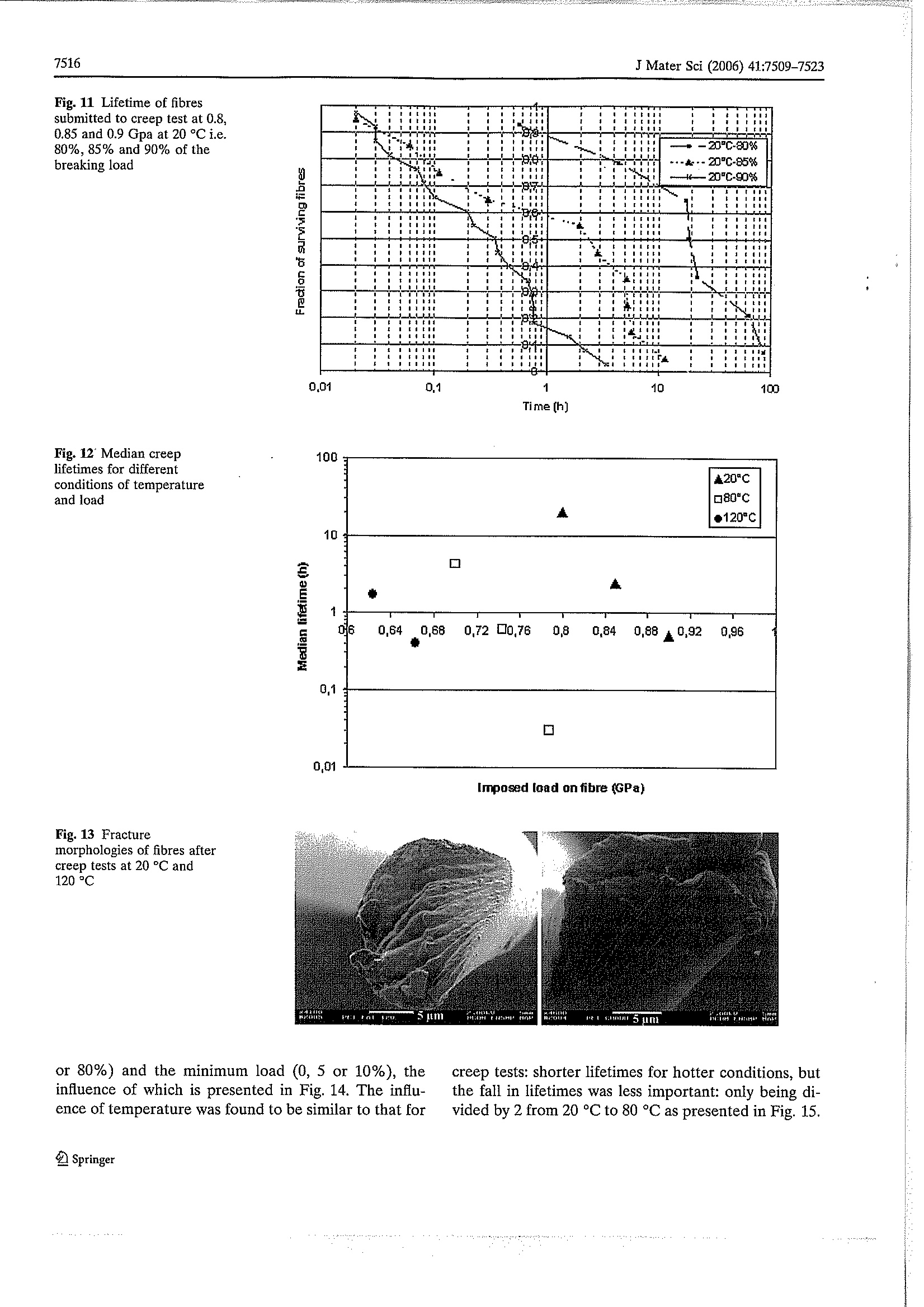
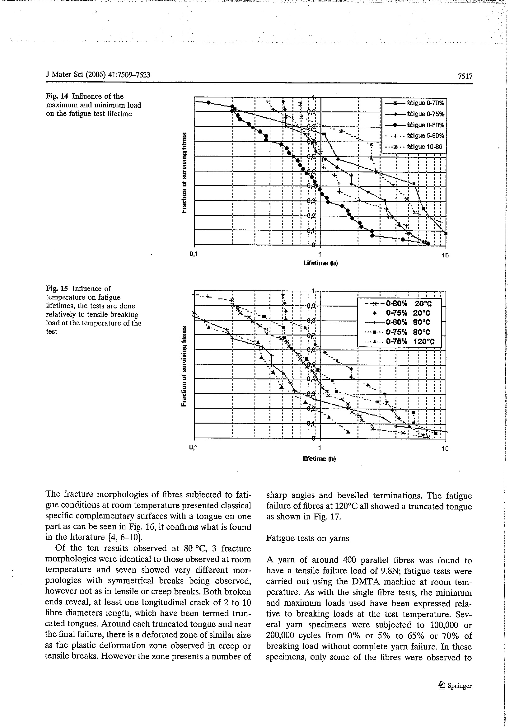
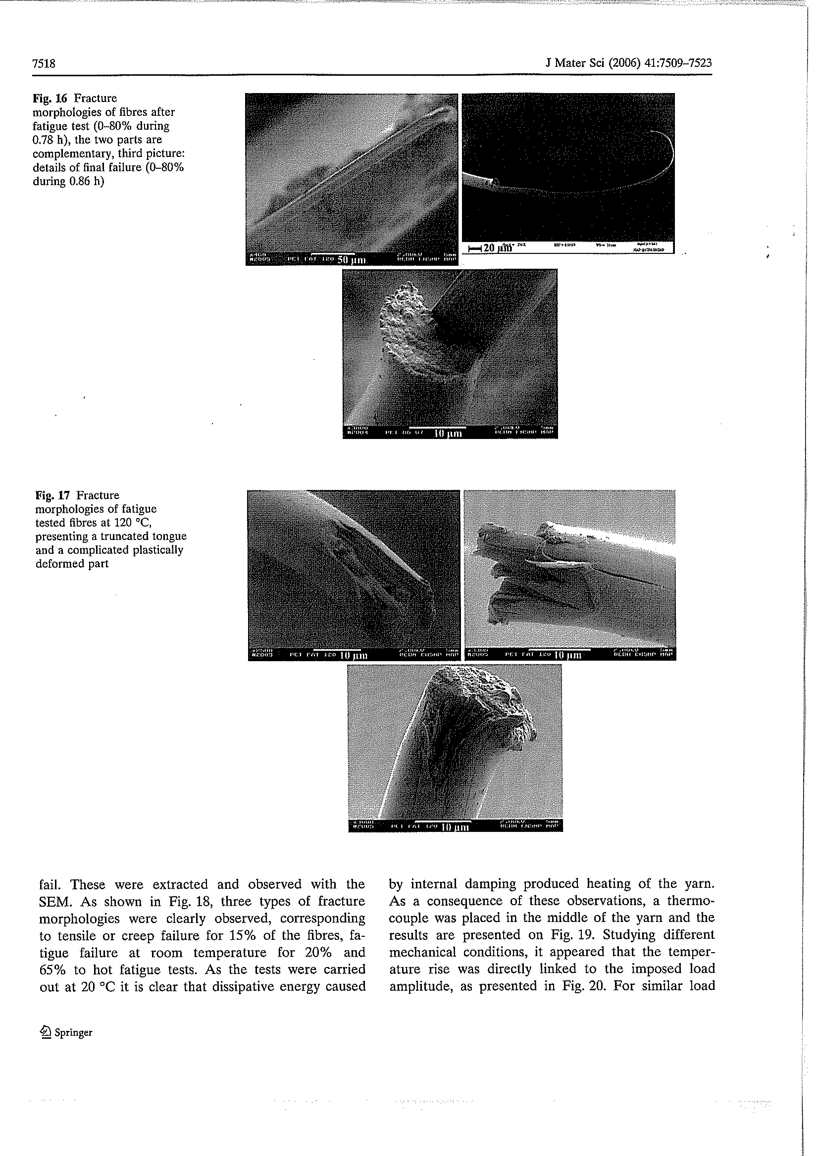
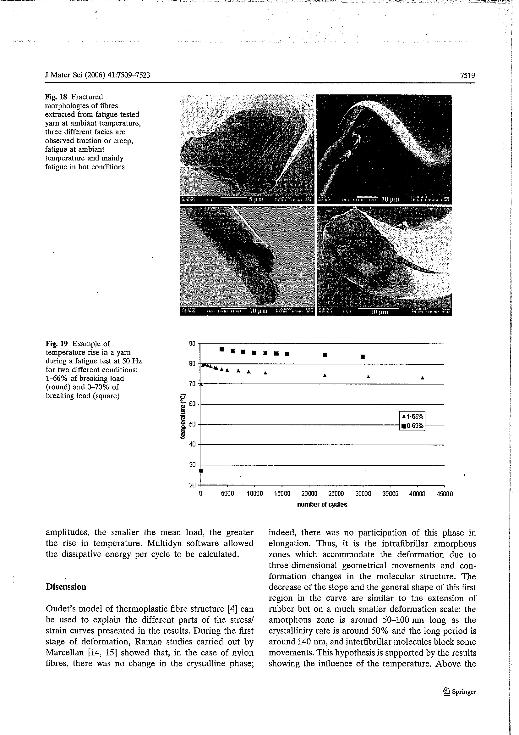
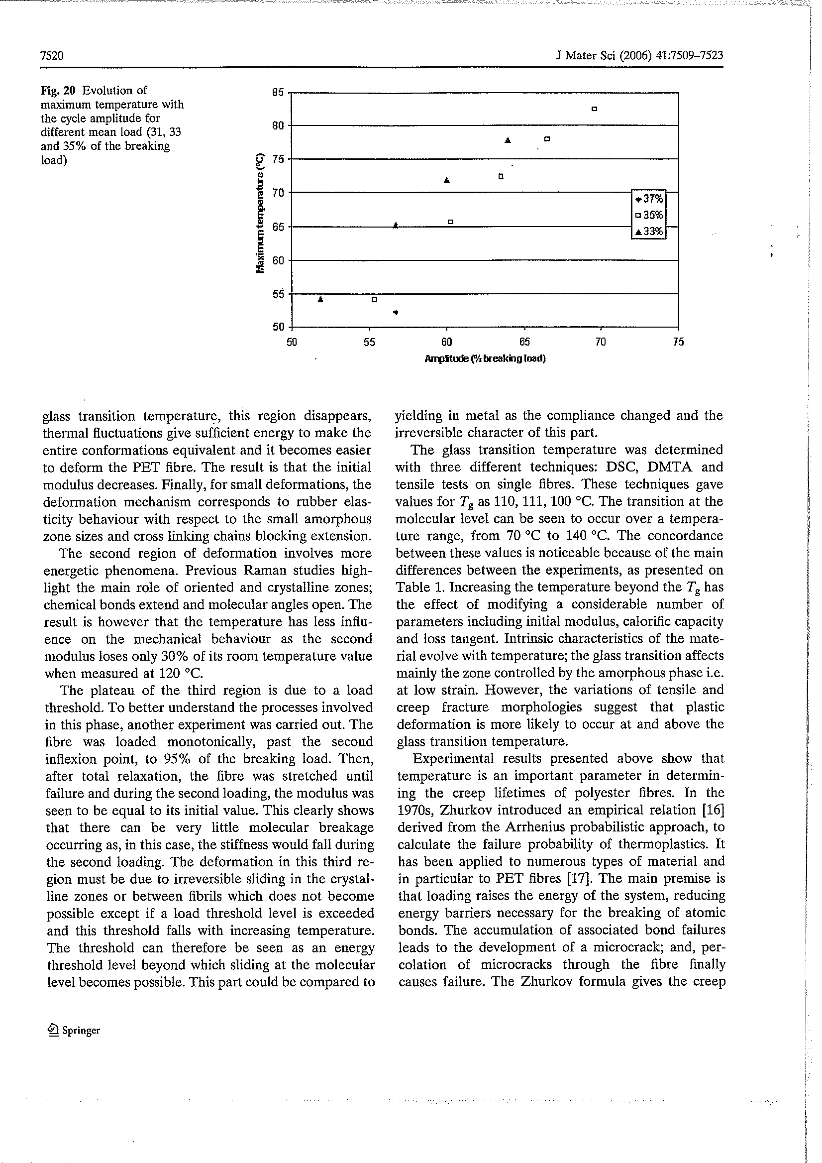
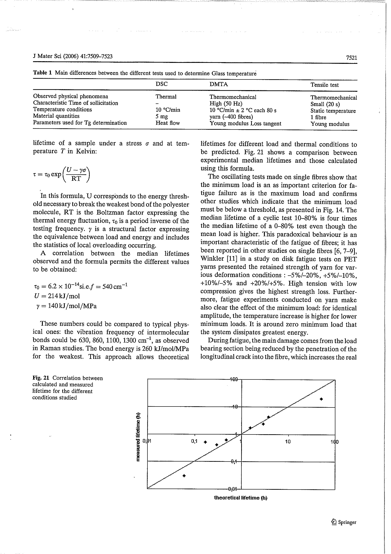
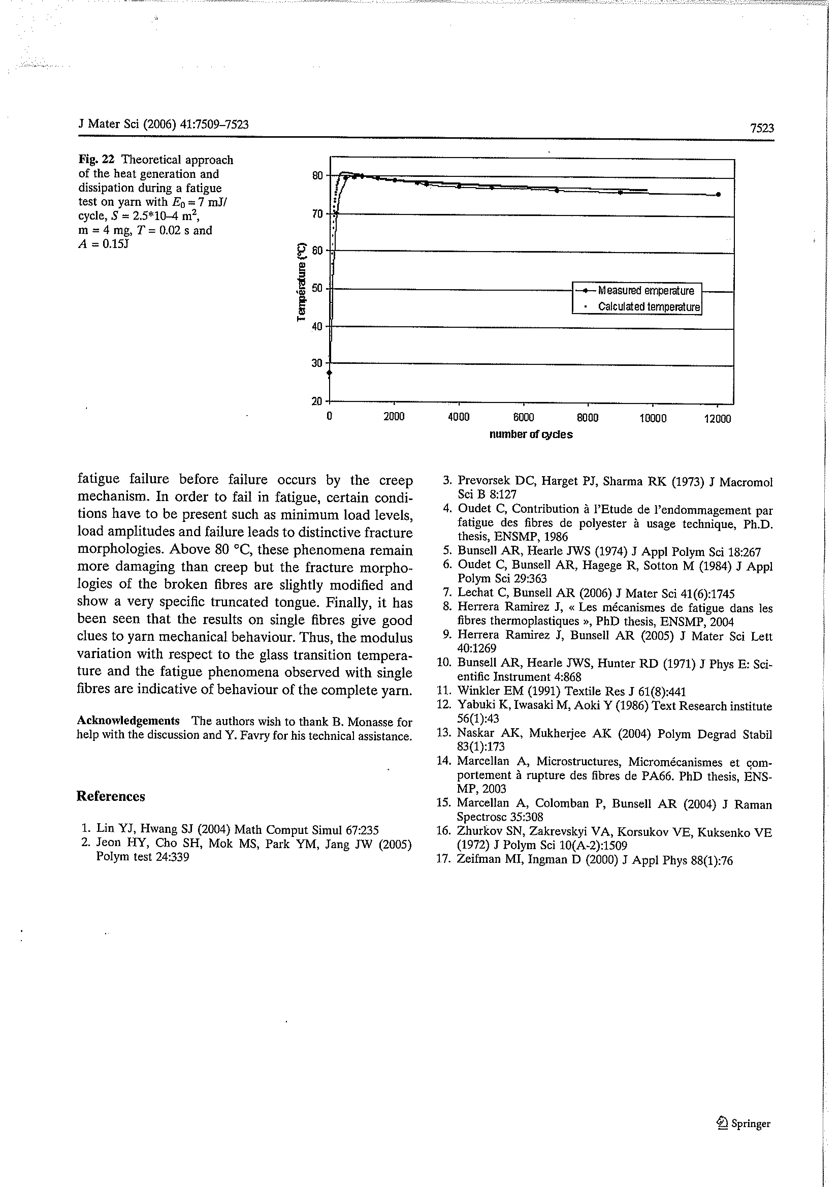
J Mater Sci (2006) 41:7509-7523DOI 10.1007/s10853-006-0835-8 7510J Mater Sci (2006) 41:7509-7523 Influence of temperature on the mechanical behaviourof polyester fibres C. Le Clerc·A. R. Bunsell· A. Piant Abstract. Thiiss study investigatess the mechanicalbehaviour of polyester fibres over a range of temper-atures by the use of ai number of experimentaltechniques including tensile, creep and fatigue tests.The influence of temperature conthe differentmechanical properties is investigated with particularemphasise on the loss of rigidity and reduction of creepand fatigue lifetimes. A precise description of thestress/strain curves of the fibres highlights the effectswith respect to the glass transition temperature. Thefatigue failure process is precisely detailed and chan-ges, at high temperature, to the classical fracturemorphology observed are presented. A comparisonbetween observations made of single fibres and yarnsprovides valuable information about the interpretationof results obtained with single fibre test to fibreassemblies. Introduction Polyester drawn into fibres possessess very usefulmechanical properties. The polyester used for fibres ispolyethylene terephthalate (PET) and they are themost widely produced synthetic fibres. In addition totextile uses, they are widely used for technical productssuch as reinforcements in tyres or belting, geotextilesand mooring ropes. For all these different uses, the C. Le Clerc (区). A. R. Bunsell· A. Piant ( Ecole des Mines de Paris, Centre des Materiaux, 91003 EvryCedex, France ) ( e-mail: Christophe.leclerc@ensmp.fr ) mechanical loadings differ as well as the environmentaland thermal conditions to which they are subjected. PET fibres possess characteristics which are useful intechnicalapplications:highlutensile strength, lowshrinkage, a good response to sustained loading, bothin creep and fatigue. Temperatures encountered canvary from 4℃ on the ocean bed to more than 120 ℃in tyre applications; some computer simulations predictan increase of temperature, from room temperature, to100 °C for a biased truck tyre at 120 km/hr[1]. For theoverall lifetime use of geotextiles, the alkalinity is ofprimary importance but temperature also acceleratesdegradation [2]. Furthermore, one of the experimentsdetailed below shows that the temperature of a simpleyarn subjected, at ambient temperature, to oscillatingmechanical stresses can reach 90 °C. Fibres can be indirect contact with air (cables) or water (ropes) or beenveloped in rubber or another polymer matrix. Ineach case, the thermal exchange rate differs so that theactual temperature of the fibres may be very differentfrom the surrounding environment. To describe the variation of mechanical behaviourof a thermoplastic with temperature, two differenttemperatures are important. First, the glass transitiontemperature (Tg) separates a ‘glassy’ state from ahighly deformable rubberlike state. The macroscopicmechanical properties are particularly dampened foramorphous materials: Initial modulus above Te can bereduced to one tenth, or less, of its value below thistemperature. In the glassy state, most of the molecularmovementsare frozenitbutthethermal energyprovided by exceeding the glass transition temperaturemeans that, greater molecular movement and newconformations become possible. Additional deforma-tion is possible under load. The second important temperature is the melting point Tr, above which, nomechanical strength remains. In order to describe the particularities of the semicrystalline structure of organic fibres, Prevorsekintroduced the concept of microfibrils [3] and Oudet,macrofibrils [4], this model is presented on Fig. 1. Amicrofibril is a longitudinal succession of crystallinezones and intrafibrillar amorphous zones, with a widthof the order of 5 nm. Oriented amorphous moleculesoccupy the spaces between fibrils and several fibrilsmake up a macrofibril and these are separated fromothers by an amorphous zone. At room temperature, the fatigue failure of fibresshows a distinctive fracture morphology, very differentfrom those obtained in creep or tensile tests. A crack isinitiated at or just below the fibre surface, it growslongitudinally along the fibre axis, slightly penetratinginto the fibre. The progressive reduction of the loadbearing section leads to an increase of stress over theremaining section, and finally failure as in tensile orcreep test. The final phase of failure shows an identicalmorphology to the tensile and creep cases with aninitiation point, plastic deformation ahead of the crackand rapid failure normal to the fibre axis. This finaltensile phase of fatigue failure is not initiated at thefatigue crack fracture surface but on or near theunbroken fibre surface. Fig. 1 Oudet’s model used to describe PET semicrystallinestructure Two complementary fracture surfaces are obtained,one showing a long tongue of material which can beseen to have been removed from the opposite com-plementary end as observed in many studies [4-9]. Thelength of the fatigue crack is often more than ten fibrediameters, and can be fifty times greater. Finally, thefatigue crack continues further than the final failure, asif the fatigue crack carries on progressing as creepdamages the remaining load bearing section. Given the wide uses to which PET are put and thewide range of conditions that they experience, it isnecessary to determine precisely their mechanicalproperties over a wide range of temperatures. Thisstudy deals with this topic: it presents results con-cerning the mechanical behaviour of the PET fibresfrom room temperature to 180℃, so encompassingthe glass transition temperature. Tensile, creep andfatigue tests have been conducted; in order to avoidany ambiguities in interpreting the results, most testswere performed on single fibres which has required theuse of testing equipment with great sensitivity for loadand displacement measurements. The study has beencompleted with tests on yarns which will be shown toconfirm and complement the results on single fibresand represent a step towards the understanding of thefailure of tows used in structures. Experimental details Material The polyester used for this study was a technical yarnwith high modulus and low shrinkage (HMLS). Eachfibre had a diameter of 18.5 pm (±0.8um) and an ini-tial modulus of 14 GPa (±0.5 GPa), a tensile strengthof 1GPa (±0.05 GPa) and elongation at tensile break of12%(±3%) at 20 °C. Fibres with these mechanicalproperties are obtained by high speed spinning so thatthe molecular orientation and the crystallinity are veryhigh; the degree of crystallinity is about 50% and thebirefringence is 0.221. Measurements on yarn Differential scanning calorimetry (DSC) The DSC studies were carried out in a nitrogenatmosphere, so as to avoid problems associated withoxidation, with a DSC 2920 modulated DSC from TAInstruments; the temperature range was 20-320 °C.The samples weighed 5-10 mg and were packed in aluminium pans to ensure good heat diffusion. Twodifferent DSC modes have been exploited. A classicalDSC, with a heating rate of 10 °C/min, was used tostudy the melting characteristics. For the glass transi-tion temperature, the modulated DSC was employedso that an oscillation of ±2℃ each 80 s was superim-posed on a heating rate of 5 °C/min. In this way,reversible and non reversible heat flows could be sep-arated. The reversible heat flow permitted the glasstransition temperature to be identified with accuracy. Dynamic thermomechanical analysis (DMTA) The thermomechanical studies have been carried outon a 01 dB Metravib machine (Viscoanalyser VA4000); two different types of experiments have. beenconducted. First, classical DMTA studies were carriedout on a yarn lightly loaded to around 1% of the tensilestrength; a small oscillation extension at a fixed fre-quency while heating from 20 to 180°℃ permitted theevolution of the modulus and the loss tangent with thetemperature to be obtained. Several fixed oscillatingfrequencies were used in these tests, in the range from5 to 100 Hz, so as to reveal the effect of time on themeasured value of T. The Multidyn software from Metravib allowed fati-gue tests on entire yarns to be performed: for example200,000 cycles of oscillation, from 0 to 70% of thetensile strength, at 50 Hz. A thermocouple was adaptedto measure any increase in temperature. A difficultywas to find suitable clamps to hold the yarn; finally,smooth jaws and wrapping the yarn around a metalform positioned behind the grips avoided sliding andfailure in the jaws. Fibre testing machine To test single fibres, Bunsell and Hearle developed anapparatus in the 1970s [10]. The fibre is held betweentwo clamps, one connected to a piezoelectric sensormounted on a screw thread connected to a motorcontrolling the crosshead, the other is fixed, for creepor tensile tests, or connected to a vibrator for fatiguetests. The key to this machine is the control of the loadimposed on the fibre. A servomechanism compares themeasured load to that required and if necessary, movesthe cross-head so as to achieve the chosen load level. Atensile test consists of a controlled increase of load, at aconstant chosen speed, until failure; a creep test con-sists however of an initial rapid load increase whichthen slows when within ten percent of the desired loadso as to avoid overshooting. In a creep test, the load is maintained constant until failure, with automaticcompensation for the elongation which occurs duringthe test. Fatigue tests are similar to creep tests in thatthe loading conditions are maintained constant despiteany elongation due to creep or plastic deformation,however a cyclic load is superimposed on a steady load.In a load controlled experiment, the maximum load isdetermined as the sum of the steady load and theamplitude (half crest to trough) of the cyclic load. Thisvalue is compared by the servo system to the requiredmaximum load. A LVDT transducer monitors thedisplacement of the crosshead during a test. Fatiguetests can be chosen to be controlled either as a functionof maximum load or displacement. The main characteristics of this system are veryprecise load control, with an accuracy of 0.1 g between0 and 100 g, a displacement with a precision of 1 um upto 20 mm. The vibrator is generally used at 50 Hz witha maximum displacement of ±3 mm. In this study, thegauge length used was 30 or 50 mm, depending on theexperimental conditions; in the case for which a largeelongation was required a gauge length of 30 mm wasused. In order to investigate the behaviour of the fibres attemperature, a cylindrical heater was added to themachine; it enabled experiments from 20 ℃ to 300 °Cto be carried out. The specimen was heated evenlyover its whole length and the grips were introducedinto the heating chamber. Hot jaws were chosen toavoid thermal gradients along fibre. An air coolingsystem was added to the grip linked to the piezoelectrictransducer to avoid signal drift. Furthermore, to refinedisplacement data during fatigue test, a capacitivecaptor was added between the vibrator and grip. Thetesting apparatus is shown in Fig. 2. The tensile tests were carried out with an elongationrate of 50%/min; so that, the whole test lasted about20 s. More than 30 tests were performed at roomtemperature so as to determine the median propertiesof the fibres. At each other temperature at least fourtests were carried out. The creep tests and fatigue testswere defined relative to a reference load which was themedian breaking load of the fibre at the tested tem-perature and normalised to the fibre diameter. Thestress/strain or strain/time curves were obtained usingATS software. Scanning electron microscopy (SEM) observations Fracture morphologies of broken fibres were observedwith a Zeiss scanning electron microscope (Gemini982). This microscope was equipped with a field effectgun which allowed working at low electron beam Fig. 2 Testing machine forsingle fibre, initiallydeveloped by Bunsell [5], withnew adjunctions: oven andcapacitive sensor voltages which, in this study, were usually 2 kV. Thisensured that the specimens were not damaged by theelectron beam and gave improved images of the fibresurfaces. The fibres were coated with a 3 nm layer ofgold/palladium to avoid charging problems. Results Tensile tests The stress/strain curve of a polyester fibre presents apoint of inflexion and a bending point which definethree different regions; the effects of temperature onthese regions are shown in Fig. 3. The first, from 0 to2% strain, at room temperature, is elastic; the initialincreasing gradient gives the initial modulus of thefibre. As the temperature was increased, this moduluswas observed to fall: from 14GPa at room temperatureto 1.5 GPa at 180 ℃ (cf. Fig. 4). The decrease was notlinear and an infiexion point can be seen to haveoccurred around 100 °C. The second region, between 2and 9% strain, at room temperature, consisted of analmost straight line, the slope of which gave the second modulus. The temperature was seen to have lessinfluence on the second modulus, as it decreased onlyfrom 10.3 GPa to 6 GPa. The third region showed afall in the slope of the curve, tending towards a stressplateau. The consequence of this behaviour was thatthere was a wider percentage dispersion in failurestrains, which was around 12±0.9% at room tempera-ture than for the breaking load which was around1±0.018 GPa. The value of the stress plateau de-creased regularly with increasing temperature, from1GPa at 20C to 0.7 GPa at 180 C, as presented inFig. 5. Over this temperature range, failure strain in-creased from 14% to more than 40%. The tensile testat 180 ℃, shown in Fig. 3, presents a clear increase instrain to failure, and the stress strain curve has amarkedly different shape from that at room tempera-ture. During creep and fatigue tests, these variationshave been taken into account. The fracture morphologies of fibres broken in ten-sion have been observed by scanning electron micros-copy. The fracture morphologies presented in Fig. 6show a two phase propagation process: first, at lowspeed, associated with plastic deformation around aninitiation point just under the surface, and then rapid Fig. 3 Tensile tests of singlefibre at differenttemperatures from 20 °℃ till180 °C Fig. 4 Initial modulus atdifferent temperatures Fig.5 Elongation and load atbreak for PET fibres,atdifferent temperatures 45 11 口 40 ·maximum elongation ·1 办 +meximum load cw 35 的 09 30 08 25 本 07 20 15 .06 10- 0,5 0 50 100 150 200 Teiperature(C) Fig.6 Fracture morphologiesof tensile tests fibres, at 20 ℃(a,b), 120C (c), and140 °C(d) b 00 5am e tHtH11 2088 5 failure perpendicular to the fibre axis. The tensilefailure is localised in the length of the fibre to less thanthe equivalent of the fibre diameter. Any effect of thetemperature on the fracture morphology is not obvi-ous, although, in a few cases, obtained at 80 °C orhigher, crack initiation started at several separatepoints. At these higher temperatures the plasticdeformation which occurred around the developingcracks was more complex than that seen at roomtemperature particularly around the initiation pointleading to a less smooth bevelled region. The softeningof the fibre which occurs above the Tg seems thereforeto have some influence on the fracture morphology. DMTA experiments A typical result obtained with the DMTA at 50Hz,using a yarn specimen, is shown in Fig. 7; the modulusdecreased during heating with an inflexion pointaround 120℃. The loss tangent was calculated fromthe phase difference between the applied load and theinduced strain over the whole temperature rangestudied. The glass transition temperature was taken asthe maximum of the loss tangent which can be seen tohave been around 136 C for that yarn tested at 50 Hz.The shift between the curves obtained with anincreasing temperature and the curves obtained with adecreasing temperature can be explained by a latentperiod corresponding to the time for all of the materialto reach the oven temperature; however, for a lowerrate of temperature increase, the difference betweenthe values obtained for Tg, obtained with the two typesof curve, decreased. The Tg has been measured for different loadingfrequencies and the results are presented in Fig. 8. Theglass transition temperature increased as the frequencyincreased as :should be expected from the timetemperature dependencerelationshipp Sseen with thermoplastics. Extrapolating the results with a zeroheating rate, gave a value for the Tg of 127 ℃from theloss tangent maximum; but for the point of inflexion inthe Young modulus curve gives a value around 111 ℃. DSC experiments In normal mode DSC, the heat flow revealed anendothermic peak centred at 257 °℃, corresponding topolyester melting, the area under the peak allowed thepercentage of crystallinity to be calculated, (Fig. 9).Thanks to the fusion enthalpy as DHg=119J/g, thecrystallinity percentage was found to be 48%, which ishigh for a semi crystalline polymer such as PET. Thepeak covered a range of temperatures but initiatedaround 200 °C. Modulated DSC experiments are pre-sented in Fig. 10 and a slight inflexion point around109°℃ is noticeable during the reverse heat flow be-tween 60 °C and 160 °C. Creep tests on single fibres Creep tests were carried out for different levels (80,85 and 90%) of failure load at the different tem-peratures considered (20, 80, 120 C). This meansthat, a test at 90% at 20°℃ corresponded to0.9 GPa, and at 120 °C, 0.7 GPa. For each thermaland mechanical condition, six or more tests havebeen conducted; their lifetimes at 20 ℃ are pre-sented in Fig. 11. The median lifetime decreased withan increase in temperature or load, as shown inFig. 12. There were more than three decades be.tween the shortest time: 0.03 h at 90%, 80℃ andthe longest 20 h at 70%, 20C. For identical im-posed testing conditions, the median lifetime wasdivided by 3.5 from 20C to 80 °C and by further 2from 80℃ to 120°C. The fracture morphologiesobtained were very similar to those obtained with Fig. 8 Glass temperatureagainst frequency ofoscillation with an heatingrate of 10 °C/min Fig.9 Classical DSC resultson5 mg of cutted fibres, peakof fusion centered at 257°C Temperature(C Fig. 10 Modulated DSC onPET fibres, bending pointcentered around 110°C 91 1 0 130 Temperature(C) tensile tests showing initiation, subcritical propaga-tion with plastic deformation and rapidfailure.Examples are presented in Fig. 13. There are alsosimilar variations, as seen in the tensile results, whentests results obtained at room temperature are com-pared to tests at higher temperatures with moreinitiation points appearing at 80 ℃ and 120 °C. In a similar way to that used for the creep tests, fatiguetests have been carried out for different mechanicaland thermal conditions related to the simple tensilebreaking loads for these conditions. Two mechanicalparameters were controlled: the maximum load (70, 75 Fig. 11 Lifetime of fibressubmitted to creep test at 0.8,0.85 and 0.9 Gpa at 20 °C i.e.80%, 85% and 90%of thebreaking load 031 rii 11A 031 -20"C-80% -30- -·-20"C-85%-------20"C-90% 1B lli jMi 1110 11 1FI 1 84- 16 tt 11 atLLL 901 si LL. tiii 1i111 10 tinrt54五41S 11 3 Time [h] Fig. 12 Median creeplifetimes for differentconditions of temperatureand load 100 Fig. 13 Fracturemorphologies of fibres aftercreep tests at 20 °C and120°C or 80%) and the minimum load (0, 5 or 10%), theinfluence of which is presented in Fig. 14. The influ-ence of temperature was found to be similar to that for creep tests: shorter lifetimes for hotter conditions, butthe fall in lifetimes was less important: only being di-vided by 2 from 20 °C to 80 °C as presented in Fig. 15. 2 Springer Fig. 14 Influence of themaximum and minimum loadon the fatigue test lifetime Lifetime ) Fig. 15 Influence oftemperature on fatiguelifetimes, the tests are donerelatively to tensile breakingload at the temperature of thetest lifetime (h The fracture morphologies of fibres subjected to fati-gue conditions at room temperature presented classicalspecific complementary surfaces with a tongue on onepart as can be seen in Fig. 16, it confirms what is foundin the literature [4,6-10]. Of the ten results observed at 80 ℃, 3 fracturemorphologies were identical to those observed at roomtemperature and seven showed very different morphologies with symmetrical breaks being observed,however not as in tensile or creep breaks. Both brokenends reveal, at least one longitudinal crack of 2 to 10fibre diameters length, which have been termed trun-cated tongues. Around each truncated tongue and nearthe final failure, there is a deformed zone of similar sizeas the plastic deformation zone observed in creep ortensile breaks. However the zone presents a number of sharp angles and bevelled terminations. The fatiguefailure of fibres at 120°C all showed a truncated tongueas shown in Fig. 17. Fatigue tests on yarns A yarn of around 400 parallel fibres was found tohave a tensile failure load of 9.8N; fatigue tests werecarried out using the DMTA machine at room tem-perature. As with the single fibre tests, the minimumand maximum loads used have been expressed rela-tive to breaking loads at the test temperature. Sev-eral yarn specimens were subjected to 100,000 or200,000 cycles from 0% or 5% to 65% or 70% ofbreaking load without complete yarn failure. In thesespecimens, only some of the fibres were observed to Fig. 17 Fracturemorphologies of fatiguetested fibres at 120 °C,presenting a truncated tongueand a complicated plasticallydeformed part fail. These were extracted and observed with theSEM. As shown in Fig. 18, three types of fracturemorphologies were clearly observed, correspondingto tensile or creep failure for 15% of the fibres, fa-tigue failure at room temperature for 20%and65% to hot fatigue tests. As the tests were carriedout at 20 °C it is clear that dissipative energy caused Fig. 16 Fracturemorphologies of fibres afterfatigue test (0-80% during0.78h), the two parts arecomplementary, third picture:details of final failure (0-80%during 0.86 h) by internal damping produced heating of the yarn.As a consequence of these observations, a thermo-couple was placed in the middle of the yarn and theresults are presented on Fig. 19. Studying differentmechanical conditions, it appeared that the temper-ature rise was directly linked to the imposed loadamplitude, as presented in Fig. 20. For similar load Fig. 18 Fracturedmorphologies of fibresextracted from fatigue testedyarn at ambiant temperature,three different facies areobserved traction or creep,fatigue at ambianttemperature and mainlyfatigue in hot conditions Fig. 19 Example oftemperature rise in a yarnduring a fatigue test at 50 Hzfor two different conditions:1-66% of breaking load(round) and 0-70% ofbreaking load (square) amplitudes, the smaller the mean load, the greaterthe rise in temperature. Multidyn software allowedthe dissipative energy per cycle to be calculated. Discussion Oudet’s model of thermoplastic fibre structure [4] canbe used to explain the different parts of the stress/strain curves presented in the results. During the firststage of deformation, Raman studies carried out byMarcellan [14, 15] showed that, in the case of nylonfibres, there was no change in the crystalline phase; indeed, there was no participation of this phase inelongation. Thus, it is the intrafibrillar amorphouszones which accommodate the deformation due tothree-dimensional geometrical movements and con-formation changes in the molecular structure. Thedecrease of the slope and the general shape of this firstregion in the curve are similar to the extension ofrubber but on a much smaller deformation scale: theamorphous zone is around 50-100 nm long as thecrystallinity rate is around 50% and the long period isaround 140 nm, and interfibrillar molecules block somemovements. This hypothesis is supported by the resultsshowing the influence of the temperature. Above the Fig. 20 Evolution ofmaximum temperature withthe cycle amplitude fordifferent mean load (31, 33and 35% of the breakingload) glass transition temperature, this region disappears,thermal fluctuations give sufficient energy to make theentire conformations equivalent and it becomes easierto deform the PET fibre. The result is that the initialmodulus decreases.Finally, for small deformations, thedeformation mechanism corresponds to rubber elas-ticity behaviour with respect to the small amorphouszone sizes and cross linking chains blocking extension. . The second region of deformation involves moreenergetic phenomena. Previous Raman studies high-light the main role of oriented and crystalline zones;chemical bonds extend and molecular angles open. Theresult is however that the temperature has less influ-ence on the mechanical behaviour as the secondmodulus loses only 30% of its room temperature valuewhen measured at 120°C. The plateau of the third region is due to a loadthreshold. To better understand the processes involvedin this phase, another experiment was carried out. Thefibre was loaded monotonically, past the secondinflexion point, to 95% of the breaking load. Then,after total relaxation, the fibre was stretched untilfailure and during the second loading, the modulus wasseen to be equal to its initial value. This clearly showsthat there can be very little molecular breakageoccurring as, in this case, the stiffness would fall duringthe second loading. The deformation in this third re-gion must be due to irreversible sliding in the crystal-line zones or between fibrils which does not becomepossible except if a load threshold level is exceededand this threshold falls with increasing temperature.The threshold can therefore be seen as an energythreshold level beyond which sliding at the molecularlevel becomes possible. This part could be compared to yielding in metal as the compliance changed and theirreversible character of this part. The glass transition temperature was determinedwith three different techniques: DSC,DMTA andtensile tests on single fibres. These techniques gavevalues for Tg as 110, 111, 100 °C. The transition at themolecular level can be seen to occur over a tempera-ture range, from 70 °℃ to 140 °C. The concordancebetween these values is noticeable because of the maindifferences between the experiments, as presented onTable 1. Increasing the temperature beyond the Tg hasthe effect of modifying a considerable number ofparameters including initial modulus, calorific capacityand loss tangent. Intrinsic characteristics of the mate-rial evolve with temperature; the glass transition affectsmainly the zone controlled by the amorphous phase i.eat low strain. However, the variations of tensile andcreep fracture morphologies suggestthat plasticdeformation is more likely to occur at and above theglass transition temperature. Experimental results presented above show thattemperature is an important parameter in determin-ing the creep lifetimes of polyester fibres. In the1970s, Zhurkov introduced an empirical relation [16]derived from the Arrhenius probabilistic approach, tocalculate the failure probability of thermoplastics. Ithas been applied to numerous types of material andin particular to PET fibres [17]. The main premise isthat loading raises the energy of the system, reducingenergy barriers necessary for the breaking of atomicbonds. The accumulation of associated bond failuresleads to the development of a microcrack; and, per-colation of microcracks through the fibre finallycauses failure. The Zhurkov formula gives the creep Table 1 Main differences between the different tests used to determine Glass temperature DSC DMTA Tensile test Observed physical phenomena Thermal Thermomechanical Thermomechanical Characteristic Time of sollicitation High (50 Hz) Small (20 s) Temperature conditions 10 °C/min 10 °C/min±2°C each 80 s Static temperature Material quantities 5 mg yarn (~400 fibres) 1 fibre Parameters used for Tg determination Heat flow Young modulus Loss tangent Young modulus lifetime of a sample under a stress a and at tem-perature T in Kelvin: In this formula, U corresponds to the energy thresh-old necessary to break the weakest bond of the polyestermolecule, RT is the Boltzman factor expressing thethermal energy fluctuation,to is a period inverse of thetesting frequency.y is a structural factor expressingthe equivalence between load and energy and includesthe statistics of local overloading occurring. A. correlation betweentthe medianlifetimesobserved and the formula permits the different valuesto be obtained: to=6.2×10-si.e.f=540cm- ?=140kJ/mol/MPa These numbers could be compared to typical phys-ical ones: the vibration frequency of intermolecularbonds could be 630, 860, 1100,1300 cm, as observedin Raman studies. The bond energy is 260 kJ/mol/MPafor the weakest. This approach allows theoretical lifetimes for different load and thermal conditions tobe predicted. Fig. 21 shows a comparison betweenexperimental median lifetimes and those calculatedusing this formula. The oscillating tests made on single fibres show thatthe minimum load is an as important criterion for fa-tigue failure as is the maximum load and confirmsother studies which indicate that the minimum loadmust be below a threshold, as presented in Fig. 14. Themedian lifetime of a cyclic test 10-80% is four timesthe median lifetime ofa 0-80% test even though themean load is higher. This paradoxical behaviour is animportant characteristic of the fatigue of fibres; it hasbeen reported in other studies on single fibres [6, 7-9],Winkler [11] in a study on disk fatigue tests on PETyarns presented the retained strength of yarn for var-ious deformation conditions : -5%/-20%, +5%/-10%,+10%/-5% and +20%/+5%. High tension with lowcompression gives the highest strength loss. Further-more, fatigue experiments conducted on yarn makealso clear the effect of the minimum load: for identicalamplitude, the temperature increase is higher for lowerminimum loads. It is around zero minimum load thatthe system dissipates greatest energy. During fatigue, the main damage comes from the loadbearing section being reduced by the penetration of thelongitudinal crack into the fibre, which increases the real Fig. 21 Correlation betweencalculated and measuredlifetime for the differentconditions studied theoreticallifetime (h) applied stress and locally accelerates creep degradation.At high temperature, the creep phenomena is amplifiedand plastic deformation occurs more easily. Indeed, assoon as the longitudinal crack is created and removes asmall section of the fibre from load bearing, theincreased stress in the remaining section in the vicinity ofthe crack causes plastic deformation and then creeprupture without real longitudinal propagation. Theresult is that the complementary fracture morphologiesare symmetrical, the three phase process of fatiguefailure at room temperature with longitudinal crackinitiation, propagation while section reduction andcreep failure is replaced by a two phase process withlongitudinal crack initiation but limited longitudinalcrack growth and accelerated creep rupture. It explainsthe differences in fracture morphologies with a trun-cated tongue but also the reduction of lifetimes which isless important than for creep tests. Fatigue crack initia-tion is, in this case, the major part of fatigue life. Thistype of failure, with a truncated tongue, has beenobserved by Winkler [11] and Naskar [13] in failed yarnsextracted from rubber after disk fatigue tests. With heatgeneration in rubber and in yarns, the temperature mustbe around the glass transition so that it is understandablethat fracture morphologies typical of high temperaturefailure can be seen even if the yarn is nominally tested atroom temperature. The studies on single fibres confirmthat the origin of this type of failure morphology is due toextension fatigue. During cyclic loading, the stress/strain curve shows ahysteresis loop the area within which corresponds to themechanical energy dissipated. This mechanical energyfollows a decreasing logarithmic law during the test andcan be expressed as: Eo initial mechanicalenergyEm=Eo-Aln(N) withA log law coefficientN number of cycles The result is an increase in yarn temperature andfollows a classical calorific law: The whole system of heat exchange with the exteriorwith a thermal exchange coefficient h and via a surfaceS, is given by: The thermal parameters Cp and h are to be found inany polymer handbook together with heat and masstransfer data, h has a natural convection part and aradiation part following Stefen’s law. An iterative calculation allows the theoretical tem-perature versus the number of cycles to be obtained, asshown in Fig. 22. The result fits very well with themeasured temperature. The temperature increase isdirectly linked to the mechanical dissipative energyi.e. the mechanical oscillation amplitude. A study ondisk fatigue tests, done by Yabuki [12], links fatiguelifetime to the inverse of the temperature of the rubbertube containing yarns subjected to cyclic sollicitation.It considers that the temperature increase is due torubber hysteresis, but the heat generation can alsocome from yarn. In addition to heat generation, the mechanical cyclicloading induces the failure of the fibres in the yarn. Atfirst, a few fibres which are more stretched than otherssupport a greater part of the applied load and breakthrough tensile elongation or rapid creep. Secondly.fibres at the periphery of the yarn and consequentlyless heated, develop fatigue cracks showing a tongue ofmaterial, as in the fatigue failure of single fibres atroom temperature. In a third stage, most of the fibresfail and show truncated tongues, characteristic offatigue damage at raised temperatures. It is clear thatload cycling of a yarn provokes the fatigue process andthe initial damage is due to the classical fatigue processas observed at room temperature on single fibres butalso due to the fatigue process at raised temperatures.Finally, when a few percent of the fibres are broken,the overload on the whole yarn causes creep andtensile failure of fibres and the failure of the completeyarn. Conclusion The transition from a glassy to a rubbery state astemperature increases, has a great influence on the firstpart of the stress/strain curve of PET fibres as it con-cerns loww energetic conformation changes. Theincrease in temperature lowers the breaking load.Creep damage is accelerated as temperature increases.The creep phenomena can be described well with theZhurkov model; it allows lifetimes for different tem-peratures and load conditions to be predicted. Cyclicmechanical loading of a single fibre can provoke Fig. 22 Theoretical approachof the heat generation anddissipation during a fatiguetest on yarn with Eo=7 mJ/cycle,S=2.5*10-4 m,m=4 mg, T=0.02 s andA=0.15J fatigue failure before failure occurs by the creepmechanism. In order to fail in fatigue, certain condi-tions have to be present such as minimum load levels,load amplitudes and failure leads to distinctive fracturemorphologies. Above 80 C, these phenomena remainmore damaging than creep but the fracture morpho-logies of the broken fibres are slightly modified andshow a very specific truncated tongue. Finally, it hasbeen seen that the results on single fibres give goodclues to yarn mechanical behaviour. Thus, the modulusvariation with respect to the glass transition tempera-ture and the fatigue phenomena observed with singlefibres are indicative of behaviour of the complete yarn. AcknowledgementstsThe authors wish to thank B. Monasse forhelp with the discussion and Y. Favry for his technical assistance. References ( 1. Lin YJ, Hwang SJ (2004) Math Comput Simul 67:235 ) ( 2. Jeon HY, Cho S H, Mok MS, Park YM, Jang JW (20 0 5) Polym test 24:339 ) 3. Prevorsek DC, Harget PJ, Sharma RK (1973) J MacromolSci B 8:127 4. Oudet C, Contribution a PEtude de Pendommagement parfatigue des fibres de polyester a usage technique, Ph.D.thesis, ENSMP, 1986 5. Bunsell AR, Hearle JWS (1974) J Appl Polym Sci 18:267 6. Oudet C, Bunsell AR, Hagege R, Sotton M (1984) J ApplPolym Sci 29:363 7. Lechat C, Bunsell AR (2006) J Mater Sci 41(6):1745 8. Herrera Ramirez J, 《 Les mecanismes de fatigue dans lesfibres thermoplastiques 》, PhD thesis, ENSMP, 2004 9. Herrera Ramirez J, Bunsell AR (2005) J Mater Sci Lett40:1269 10. Bunsell AR, Hearle JWS, Hunter RD (1971) J Phys E: Sci-entific Instrument 4:868 11. Winkler EM (1991) Textile Res J 61(8):441 12. Yabuki K, Iwasaki M, Aoki Y (1986)Text Research institute56(1):43 13. Naskar AK, Mukherjee AK (2004) Polym Degrad Stabil83(1):173 14. Marcellan A, Microstructures, Micromecanismes et com.portement a rupture des fibres de PA66. PhD thesis, ENS_MP,2003 15. Marcellan A, Colomban P, Bunsell AR (2004) J RamanSpectrosc 35:308 16. Zhurkov SN, Zakrevskyi VA, Korsukov VE, Kuksenko VE(1972) J Polym Sci 10(A-2):1509 17. Zeifman MI, Ingman D (2000) J Appl Phys 88(1):76 Springer
确定
还剩13页未读,是否继续阅读?

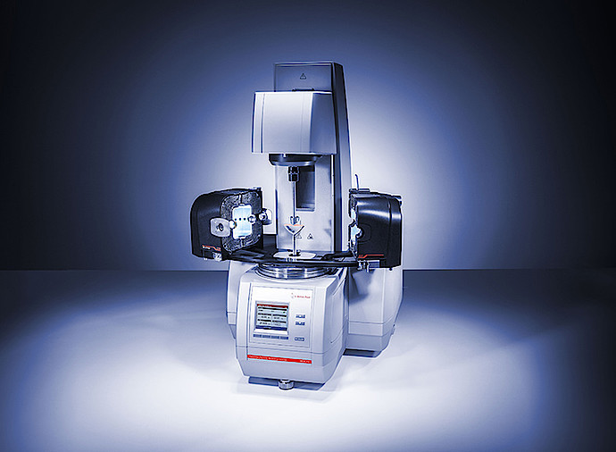
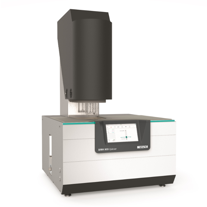
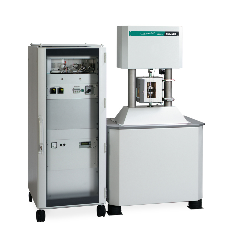
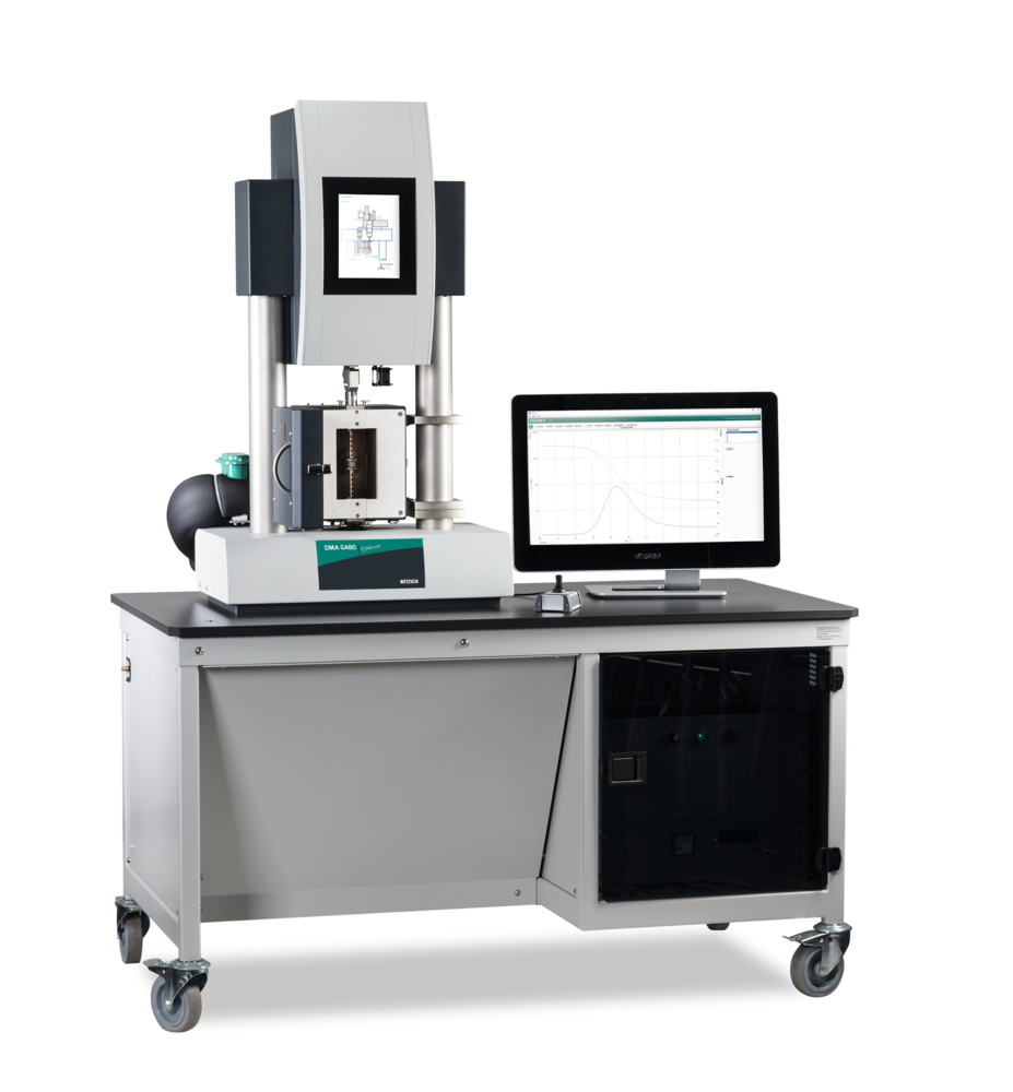
仪尊科技有限公司为您提供《涤纶纤维中温度对力学性能的影响检测方案(热机械分析仪)》,该方案主要用于合成纤维中力学性能检测,参考标准--,《涤纶纤维中温度对力学性能的影响检测方案(热机械分析仪)》用到的仪器有动态热机械分析仪
推荐专场