


方案详情
文
ESPion高级Langmuir探针(Advanced Langmuir Probes for Electrical Plasma Characterisation)可快速、可靠、精确地进行等离子体诊断,是最先进可靠的 Langmuir 探针。
应用:
· 蚀刻/沉积/ 清洁等离子体
· 脉冲等离子体操作
· 离子密度 (Ni & Gi)
· 电子温度(Te & EEDF)
· 电子密度(Ne)
· 等离子体电位
· Debye 长度,悬浮电位
方案详情

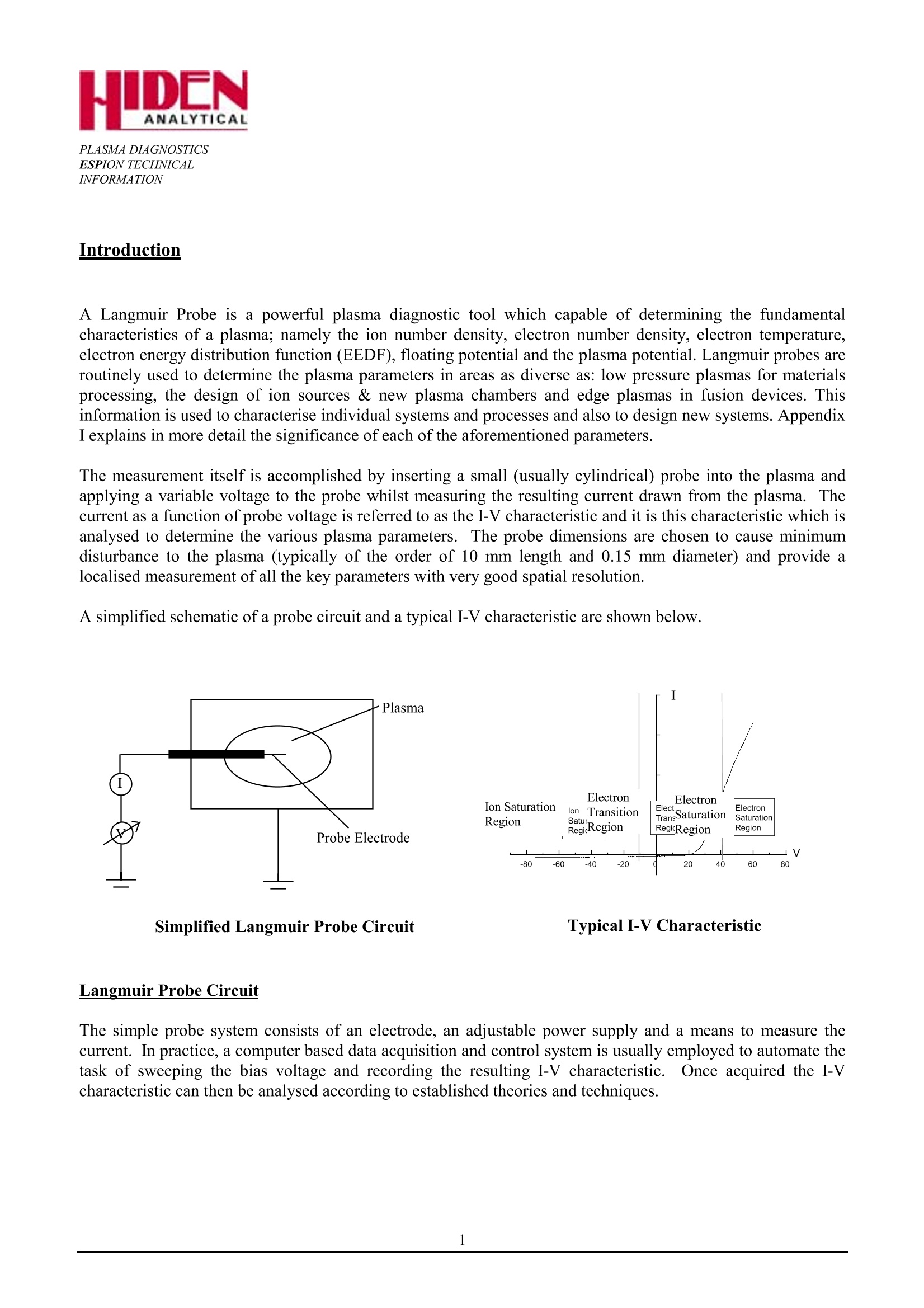
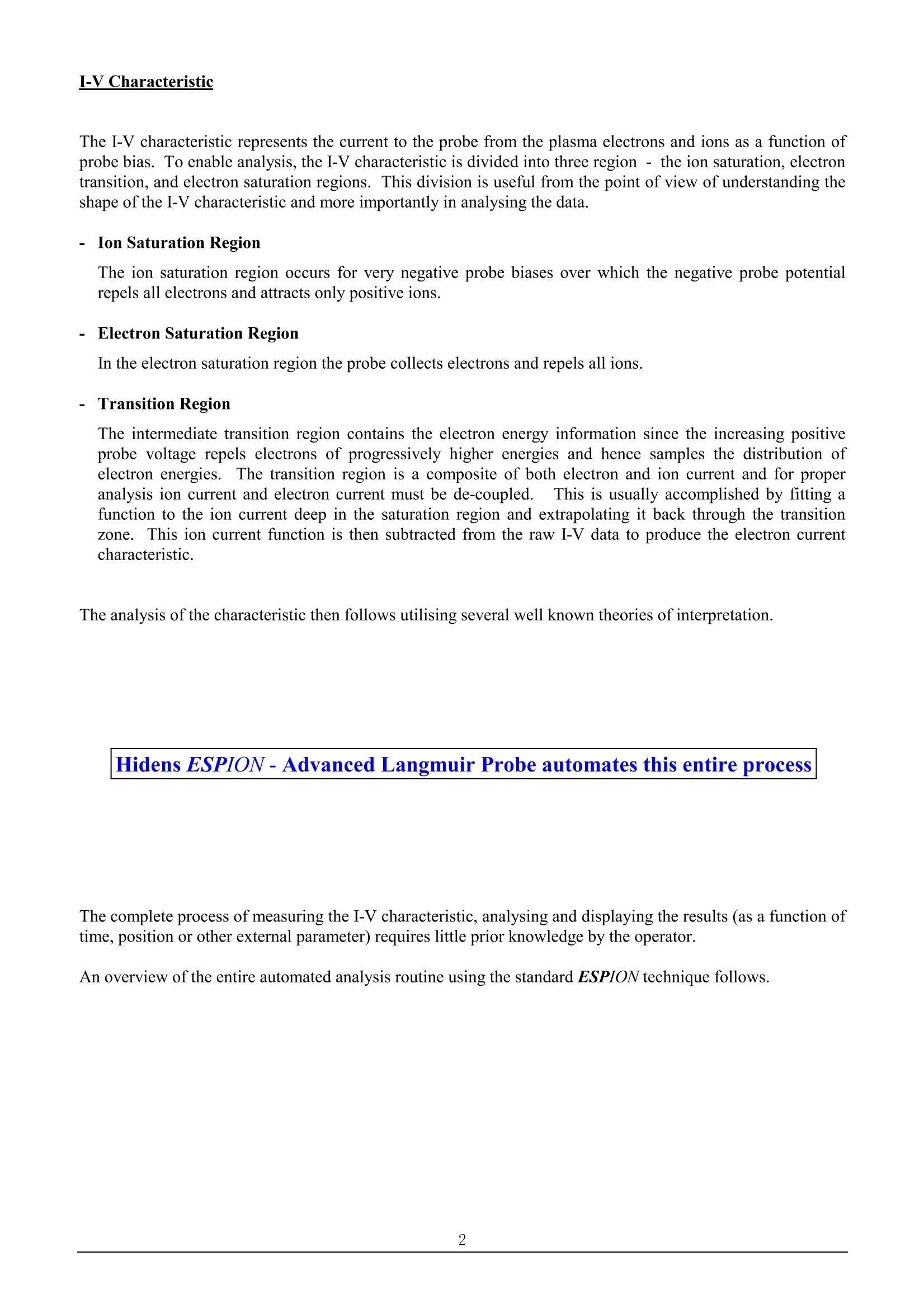
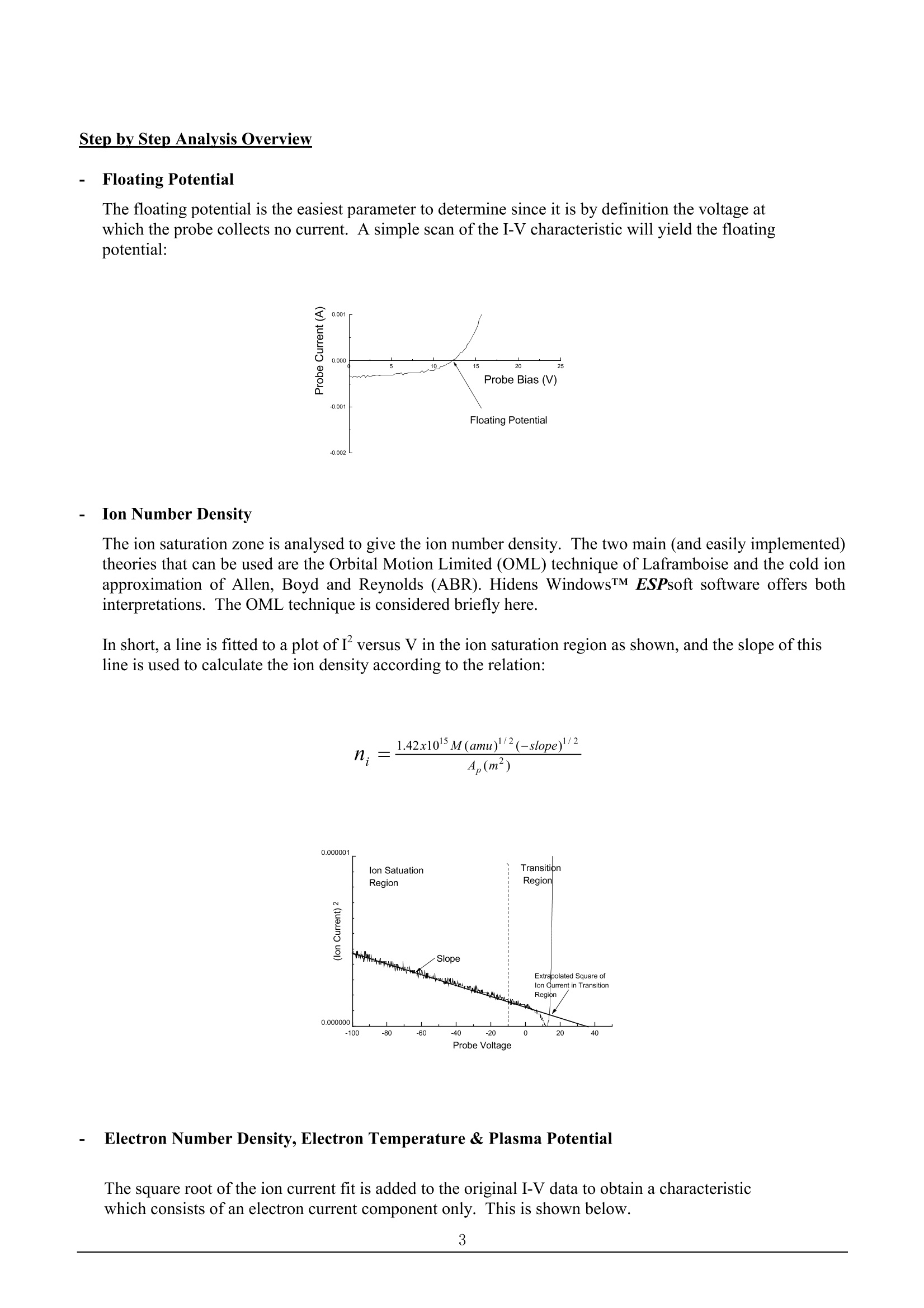
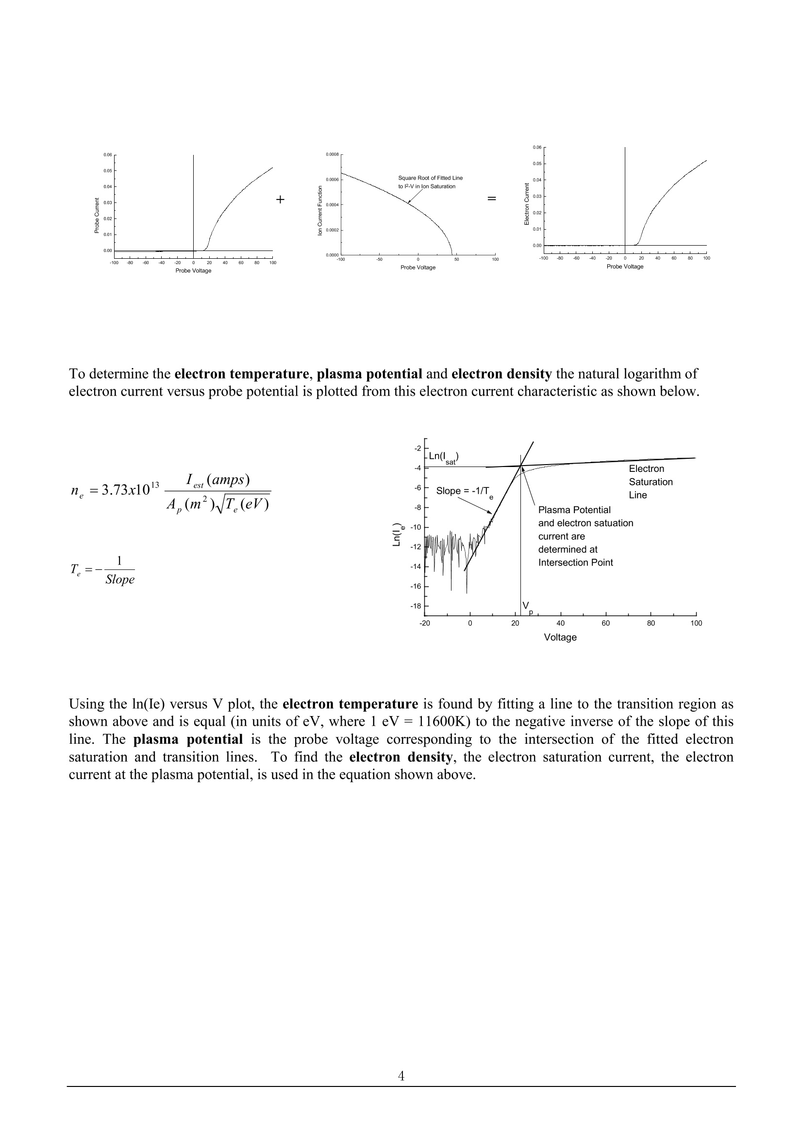
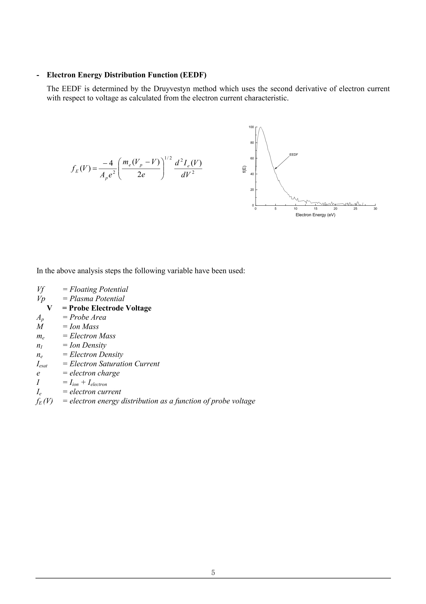
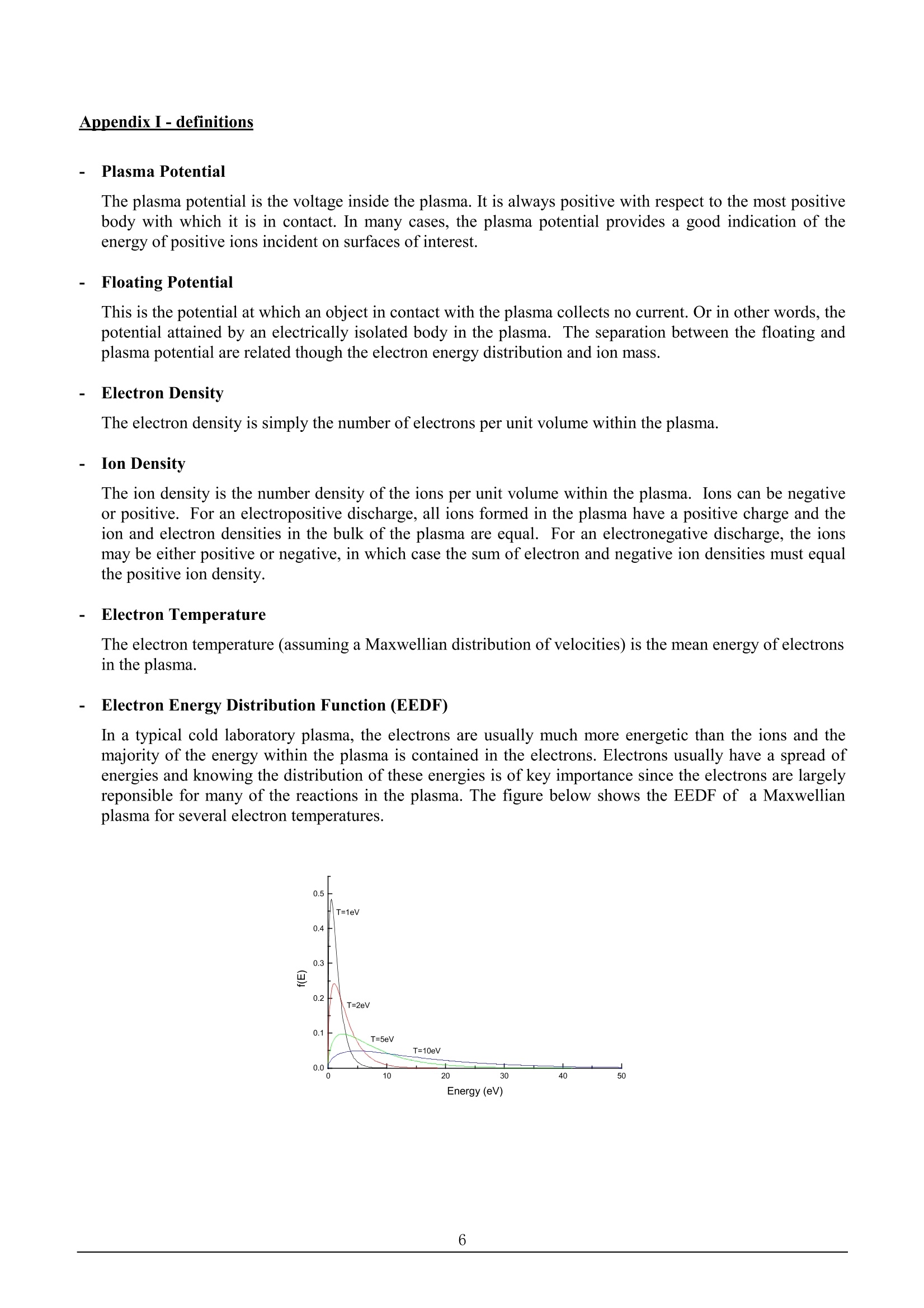
PLASMA DIAGNOSTICSESPION TECHNICALINFORMATION Introduction A Langmuir Probe is a powerful plasma diagnostic tool which capable of determining the fundamentalcharacteristics of a plasma; namely the ion number density, electron number density, electron temperature.electron energy distribution function (EEDF), floating potential and the plasma potential. Langmuir probes areroutinely used to determine the plasma parameters in areas as diverse as: low pressure plasmas for materialsprocessing, the design of ion sources & new plasma chambers and edge plasmas in fusion devices. Thisinformation is used to characterise individual systems and processes and also to design new systems. AppendixI explains in more detail the significance of each of the aforementioned parameters. The measurement itself is accomplished by inserting a small (usually cylindrical) probe into the plasma andapplying a variable voltage to the probe whilst measuring the resulting current drawn from the plasma..Thecurrent as a function of probe voltage is referred to as the I-V characteristic and it is this characteristic which isanalysed to determine the various plasma parameters.. The probe dimensions are chosen to cause minimumdisturbance to the plasma (typically of the order of 10 mm length and 0.15 mm diameter) and provide alocalised measurement of all the key parameters with very good spatial resolution. A simplified schematic of a probe circuit and a typical I-V characteristic are shown below. Simplified Langmuir Probe Circuit Typical I-V Characteristic Langmuir Probe Circuit The simple probe system consists of an electrode, an adjustable power supply and a means to measure thecurrent. In practice, a computer based data acquisition and control system is usually employed to automate thetask of sweeping the bias voltage and recording the resulting I-V characteristic..Once acquired the I-Vcharacteristic can then be analysed according to established theories and techniques. I-V Characteristic The I-V characteristic represents the current to the probe from the plasma electrons and ions as a function ofprobe bias. To enable analysis, the I-V characteristic is divided into three region-the ion saturation, electrontransition, and electron saturation regions. This division is useful from the point of view of understanding theshape of the I-V characteristic and more importantly in analysing the data. - Ion Saturation Region The ion saturation region occurs for very negative probe biases over which the negative probe potentialrepels all electrons and attracts only positive ions. - Electron Saturation Region In the electron saturation region the probe collects electrons and repels all ions. - Transition Region The intermediate transition region contains the electron energy information since the increasing positiveprobe voltage repels electrons of progressively higher energies and hence samples the distribution ofron eTelectron energies.he transition region is a composite of both electron and ion current and for properanalysis ion current and electron current must be de-coupled.i.This is usually accomplished by fitting afunction to the ion current deep in the saturation region and extrapolating it back through the transitionzone.This ion current function is then subtracted from the raw I-V data to produce the electron currentcharacteristic. The analysis of the characteristic then follows utilising several well known theories of interpretation. Hidens ESPION-Advanced Langmuir Probe automates this entire process The complete process of measuring the I-V characteristic, analysing and displaying the results (as a function oftime, position or other external parameter) requires little prior knowledge by the operator. An overview of the entire automated analysis routine using the standard ESPION technique follows. Step by Step Analysis Overview -Floating Potential The floating potential is the easiest parameter to determine since it is by definition the voltage atwhich the probe collects no current. A simple scan of the I-V characteristic will yield the floatingpotential: -Ion Number Density The ion saturation zone is analysed to give the ion number density. The two main (and easily implemented)theories that can be used are the Orbital Motion Limited (OML) technique of Laframboise and the cold ionapproximation of Allen, Boyd and Reynolds (ABR). Hidens WindowsTM ESPsoft software offers bothinterpretations. The OML technique is considered briefly here. In short, a line is fitted to a plot ofIversus V in the ion saturation region as shown, and the slope of thisline is used to calculate the ion density according to the relation: n = 1.42x10lM(amu)2(-slope)2/2 4,(m²) -Electron Number Density, Electron Temperature & Plasma Potential The square root ofthe ion current fit is added to the original I-V data to obtain a characteristicwhich consists of an electron current component only. This is shown below. To determine the electron temperature, plasma potential and electron density the natural logarithm ofelectron current versus probe potential is plotted from this electron current characteristic as shown below. Using the ln(Ie) versus V plot, the electron temperature is found by fitting a line to the transition region asshown above and is equal (in units ofeV, where 1 eV=11600K) to the negative inverse of the slope of thisline. The plasma potential is the probe voltage corresponding to the intersection of the fitted electronsaturation and transition lines.To find the electron density, the electron saturation current, the electroncurrent at the plasma potential, is used in the equation shown above. -IElectron Energy Distribution Function (EEDF) The EEDF is determined by the Druyvestyn method which uses the second derivative of electron currentwith respect to voltage as calculated from the electron current characteristic. In the above analysis steps the following variable have been used: =Floating Potential = Plasma Potential V =Probe Electrode Voltage 4=Probe Area M =Ion Mass me =Electron Mass =Ion Density =Electron Density esat =Electron Saturation Current = electron charge =lion +Ielectron =electron current fe(V) =electron energy distribution as a function of probe voltage Appendix I-definitions -1Plasma Potential The plasma potential is the voltage inside the plasma. It is always positive with respect to the most positivebody with which it is in contact. In many cases, the plasma potential provides a good indication of theenergy of positive ions incident on surfaces of interest. -1Floating Potential This is the potential at which an object in contact with the plasma collects no current. Or in other words,thepotential attained by an electrically isolated body in the plasma. The separation between the floating andplasma potential are related though the electron energy distribution and ion mass. -Electron Density The electron density is simply the number of electrons per unit volume within the plasma. -IIon Density The ion density is the number density of the ions per unit volume within the plasma. Ions can be negativeor positive. For an electropositive discharge, all ions formed in the plasma have a positive charge and theion and electron densities in the bulk of the plasma are equal. For an electronegative discharge, the ionsmay be either positive or negative, in which case the sum of electron and negative ion densities must equalthe positive ion density. Electron Temperature The electron temperature (assuming a Maxwellian distribution of velocities) is the mean energy of electronsin the plasma. -1Electron Energy Distribution Function (EEDF) In a typical cold laboratory plasma, the electrons are usually much more energetic than the ions and themajority of the energy within the plasma is contained in the electrons. Electrons usually have a spread ofenergies and knowing the distribution of these energies is of key importance since the electrons are largelyreponsible for many of the reactions in the plasma. The figure below shows the EEDF of a Maxwellianplasma for several electron temperatures. Appendix ⅡI - Frequently asked questions (FAQs) The information of the preceeding sections provides a general overview of the Langmuir probe technique. Thefollowing FAQs and corresponding responses attempt to deal with issues arising in specific applications bydescribing the features of Hidens ESPION probe which have been specifically developed. Q1 How can the ESPION help me? A1The ESPION provides detailed information about the key parameters in your plasma processKnowledge of these can assist in identifying processing problems, in designing and troubleshooting newprocesses and in checking for deviations between chambers. Q2 My process uses depositing / etching gases, will the ESPION probe become contaminated and will thisaffect the results? A2: The ESPION probe has been developed with these applications in mind. ESPsoft softwareenables theactive probe tip to be automatically toggled between acquire and clean cycles between individual scansensuring that data is always acquired with a clean probe tip. Cleaning is achieved by ion bombardmentsputtering or by joule heating when collecting an electroncurrent. Q3 My plasma is generated with RF voltages, will this affect the measurements? A3In an RF plasma, a significant AC voltage can develop between the plasma and probe tip. The ESPIONuses a passive technique incorporating a high frequency compensation electrode together with a string ofinductors immediately behind the tip, effectively a tuned LC circuit,in order to remove this ACcomponent and its harmonics. The inductors are air cooledto prevent degradation in hot environments. Q4What type of tip materials are used? A4.ESPION can be supplied with many different types of tip materials including Molybdenum, Tungsten,Platinum etc. The tips are easily user interchangeable. Q5 My chamber is often coated with insulating materials, does this affect the measurements? A5LESPION employs an integral low frequency reference electrode which compensates for chamberswith poor or no ground reference. The reference probe also serves to track andeliminate low frequencynoise due to mains/power supply instabilities. Q6 Can I use pulsed plasmas? A6Yes. The ESPION probe is capable of making measurements in plasmas which are modulated upto 100kHz. The gating resolution is 1 microsecond. The complete timing electronics, gating, delay etc. arecontained within the ESPION control unit and controlled by ESPsoft software so that only the pulsewhich modulates the plasma is required as an input. Q7 Can I make spatially resolved measurements? A7 Yes. The ESPION can be supplied with an automated z-drive which is controlled via ESPsoft softwareallowing data to be taken as a function of position within the chamber.
确定
还剩5页未读,是否继续阅读?

产品配置单
北京英格海德分析技术有限公司为您提供《等离子体诊断中离子密度检测方案(表面处理仪)》,该方案主要用于其他中离子密度检测,参考标准--,《等离子体诊断中离子密度检测方案(表面处理仪)》用到的仪器有高级朗缪尔探针(Langmuir Probe)
推荐专场

相关方案
更多