


方案详情
文
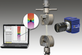
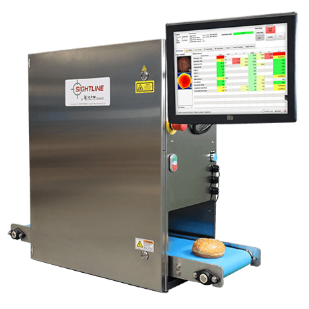
非介入式全场应变形变测量,可用于各种材料压缩和拉伸形变试验中,也可用于冶金,地质,矿产能源等研究和工业领域。
方案详情

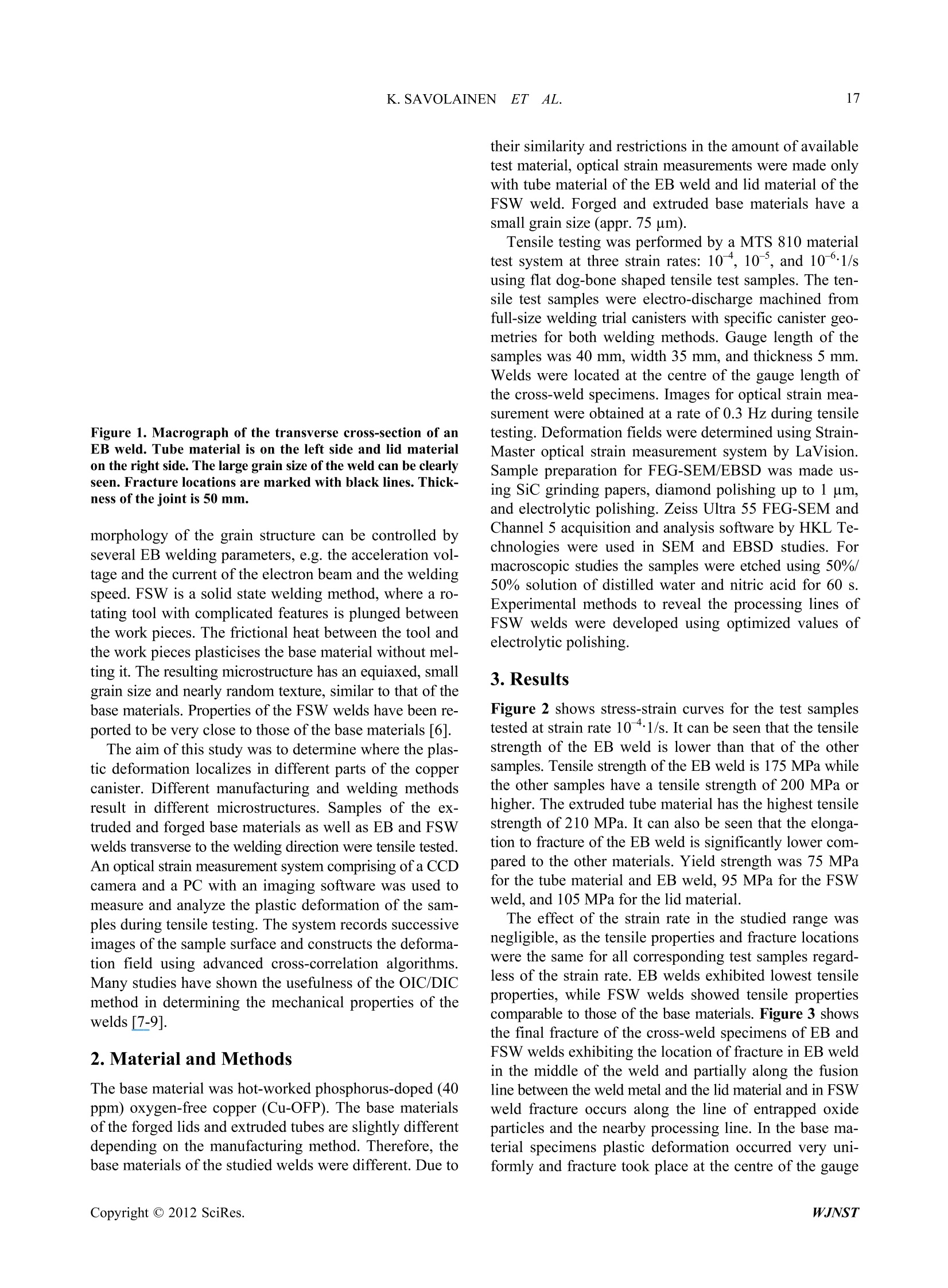
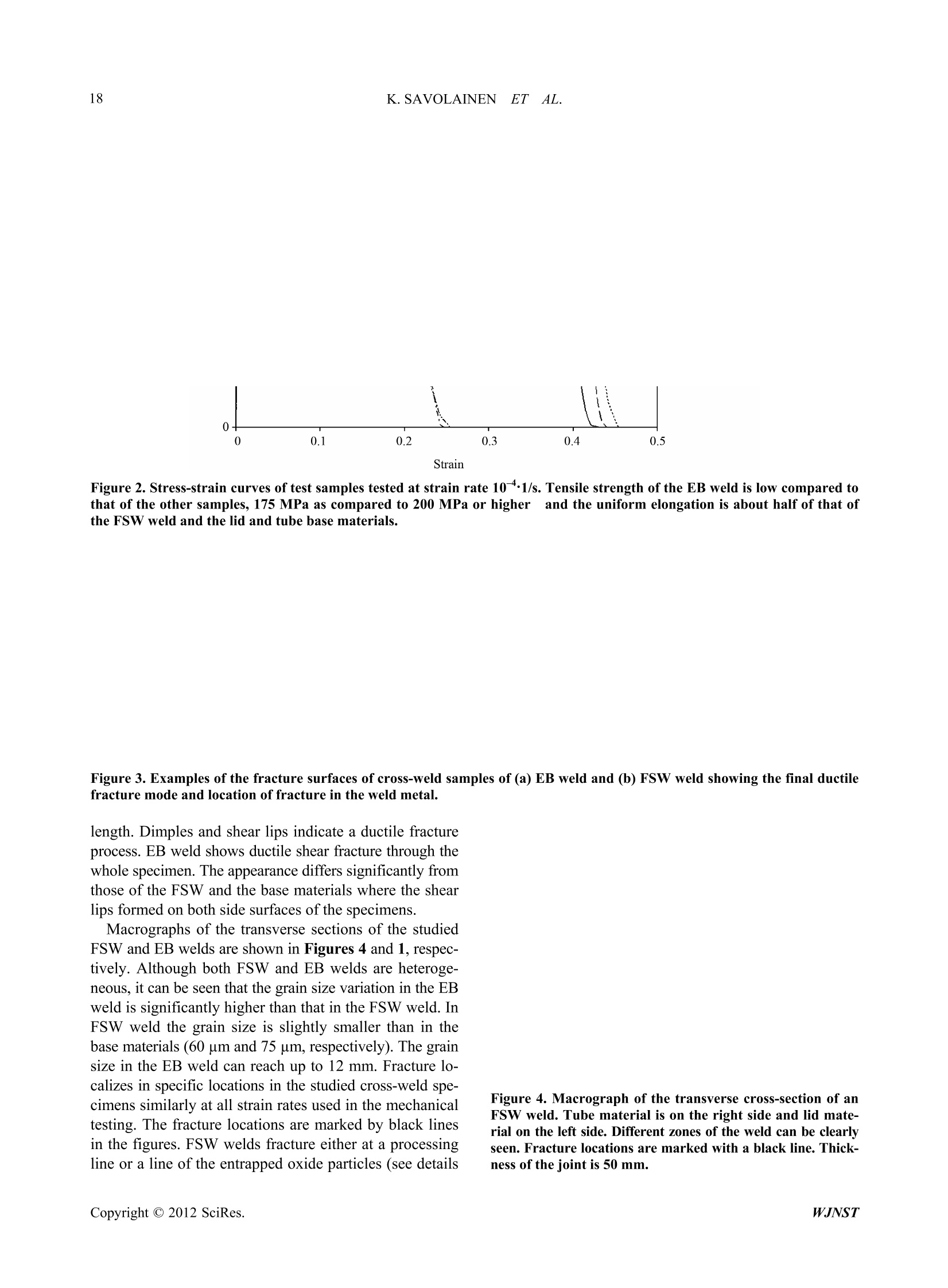
ResearchGate World Journal of Nuclear Science and Technology, 2012,2,16-22doi:10.4236/wjnst.2012.21003 Published Online January 2012 (http://www.SciRP.org/journal/wjnst) See discussions, stats, and author profiles for this publication at: https://www.researchgate.net/publication/228449310 Localization of Plastic Deformation in CopperCanisters for Spent Nuclear Fuel Article in World Journal of Nuclear Science and Technology·January 2012 DOI: 10.4236/wjnst.2012.21003 CITATIONS0 READS 32 3 authors,including: Tapio Saukkonen Hannu Hanninen Aalto University Aalto Universitv 80 PUBLICATIONS 321 CITATIONS 493 PUBLICATIONS 2,616 CITATIONS SEE PROFILE SEE PROFILE Some of the authors of this publication are also working on these related projects: All content following this page was uploaded by Tapio Saukkonen on 03 April 2014. The user has requested enhancement of the downloaded file. All in-text references underlined in blue are added to the original documentand are linked to publications on ResearchGate, letting you access and read them immediately. Localization of Plastic Deformation in Copper Canistersfor Spent Nuclear Fuel Kati Savolainen, Tapio Saukkonen, Hannu Hanninen School of Engineering Laboratory of Engineering Materials, Aalto University, Espoo, FinlandEmail: Kati.Savolainen@hut.fi Received October 3, 2011; revised November 4, 2011; accepted December 8, 2011 ABSTRACT Localization of plastic deformation in different parts (extruded and forged base materials as well as EB and FSW welds)of the corrosion barrier copper canister for final disposal of spent nuclear fuel was studied using tensile testing, opticalstrain measurement, scanning electron microscopy (SEM), and electron back-scatter diffraction (EBSD). Results showthat in the base materials plastic deformation occurs very uniformly. In FSW welds the deformation localizes in theweld either at the processing line or at a line of entrapped oxide particles. In EB welds the deformation localizes to theequally oriented large grains at the weld centreline or at the steep grain size gradient in the fusion line. Keywords: Copper; Deformation; Localization; Friction Stir Welding; Electron Beam Welding 1.Introduction In Finland and Sweden the spent nuclear fuel will be en-capsulated and deposited into long-term repositories deepin the bedrock[1,2]. The spent nuclear fuel will be placedin cast iron inserts surrounded by corrosion barrier cop-per canisters. The 50 mm thick copper canisters consistof an extruded tubular body and forged lid and bottomparts. The tubes and the lids/bottoms will be joined usingeither electron beam (EB) or friction stir welding (FSW).Different parts of the copper canister have inhomogene-ous grain structures and the canister itself contains dis-continuities and welds as well as possible minor defects,which cause stress concentrations. These regions may havea significant influence on the deformation of the canisterduring its lifetime, and their impact on the damage toler-ance of the copper canister must be known. Plastic de-formation of the canister caused by the repository condi-tions, such as hydrostatic pressure and bentonite swelling,will not be distributed evenly around the canister, butinstead it will concentrate to certain locations. Microstruc-tural defects, geometric discontinuities, as well as micro-structural heterogeneity and residual stresses and strainsof the welds, in particular, localize plastic deformation. Residual stress and strain profiles in constrained thick-section copper welds on a local scale and their relaxationunder creep and irradiation has not been assessed in de-tail. Also the relationship of strain localization and strainhistory to cold work distribution in copper canister hasnot been explored. The amount of residual plastic strain ( "Corresponding author. ) is known to have an effect on different long-term materi-als properties. For instance, effect of prestrain (disloca-tion density) on creep of copper has been shown [3]. Inaustenitic AISI 304 stainless steel the amount of coldwork exceeding 20% is known to result in initiation ofthe stress corrosion cracking [4]. Thus, when wanting toascertain and evaluate the integrity of the copper canisterit is very important to know the material properties evenin very small localized areas. Electron backscatter diffrac-tion (EBSD) and electron microscopy have in recent yearsproved to be a promising method to study the plastic strainand other material properties in localized areas. However,due to time constraint when wanting to map large areas,it is beneficial to be able to concentrate only on the criti-cal areas. The different regions of a weld are typicallyexhibiting large variations of residual plastic strain and va-rious discontinuities in the material properties. The opti-cal strain measurement using large test samples contain-ing the whole weld area is an ideal method to detect thecritical areas for strain localization, which can later bestudied with electron microscopy in detail. Welding of 50 mm thick copper is difficult and the twocurrently available methods are EBW and FSW. In EBW,a beam of high-energy electrons locally melts the mate-rial to be welded and as the beam passes, the material so-lidifies producing a very distinctive grain structure. Soli-dification initiates epitaxially on the base material on bothsides of the weld [5]. The solidification forms long co-lumnar grains, which turn to the welding direction (Fig-ure 1). At the centreline of the weld the long columnargrains are almost parallel to the welding direction. The Figure 1. Macrograph of the transverse cross-section of anEB weld. Tube material is on the left side and lid materialon the right side. The large grain size of the weld can be clearlyseen. Fracture locations are marked with black lines. Thick-ness of the joint is 50 mm. morphology of the grain structure can be controlled byseveral EB welding parameters, e.g. the acceleration vol-tage and the current of the electron beam and the weldingspeed. FSW is a solid state welding method, where a ro-tating tool with complicated features is plunged betweenthe work pieces. The frictional heat between the tool andthe work pieces plasticises the base material without mel-ting it. The resulting microstructure has an equiaxed, smallgrain size and nearly random texture, similar to that of thebase materials. Properties of the FSW welds have been re-ported to be very close to those of the base materials [6]. The aim of this study was to determine where the plas-tic deformation localizes in different parts of the coppercanister. Different manufacturing and welding methodsresult in different microstructures. Samples of the ex-truded and forged base materials as well as EB and FSWwelds transverse to the welding direction were tensile tested.An optical strain measurement system comprising of a CCDcamera and a PC with an imaging software was used tomeasure and analyze the plastic deformation of the sam-ples during tensile testing. The system records successiveimages of the sample surface and constructs the deforma-tion field using advanced cross-correlation algorithms.Many studies have shown the usefulness of the OIC/DICmethod in determining the mechanical properties of thewelds [7-9]. 2. Material and Methods The base material was hot-worked phosphorus-doped (40ppm) oxygen-free copper (Cu-OFP). The base materialsof the forged lids and extruded tubes are slightly differentdepending on the manufacturing method. Therefore, thebase materials of the studied welds were different. Due to their similarity and restrictions in the amount of availabletest material, optical strain measurements were made onlywith tube material of the EB weld and lid material of theFSW weld. Forged and extruded base materials have asmall grain size (appr.75 um). Tensile testing was performed by a MTS 810 materialtest system at three strain rates: 10 , 10, and 101/susing flat dog-bone shaped tensile test samples. The ten-sile test samples were electro-discharge machined fromfull-size welding trial canisters with specific canister geo-metries for both welding methods. Gauge length of thesamples was 40 mm, width 35 mm, and thickness 5 mm.Welds were located at the centre of the gauge length ofthe cross-weld specimens. Images for optical strain mea-surement were obtained at a rate of 0.3 Hz during tensiletesting. Deformation fields were determined using Strain-Master optical strain measurement system by LaVision.Sample preparation for FEG-SEM/EBSD was made us-ing SiC grinding papers, diamond polishing up to1 um,and electrolytic polishing. Zeiss Ultra 55 FEG-SEM andChannel 5 acquisition and analysis software by HKL Te-chnologies were used in SEM and EBSD studies. Formacroscopic studies the samples were etched using 50%/50% solution of distilled water and nitric acid for 60 s.Experimental methods to reveal the processing lines ofFSW welds were developed using optimized values ofelectrolytic polishing. 3.Results Figure 2 shows stress-strain curves for the test samplestested at strain rate 10-41/s. It can be seen that the tensilestrength of the EB weld is lower than that of the othersamples. Tensile strength of the EB weld is 175 MPa whilethe other samples have a tensile strength of 200 MPa orhigher. The extruded tube material has the highest tensilestrength of 210 MPa. It can also be seen that the elonga-tion to fracture of the EB weld is significantly lower com-pared to the other materials. Yield strength was 75 MPafor the tube material and EB weld, 95 MPa for the FSWweld, and 105 MPa for the lid material. The effect of the strain rate in the studied range wasnegligible, as the tensile properties and fracture locationswere the same for all corresponding test samples regard-less of the strain rate. EB welds exhibited lowest tensileproperties, while FSW welds showed tensile propertiescomparable to those of the base materials. Figure 3 showsthe final fracture of the cross-weld specimens of EB andFSW welds exhibiting the location of fracture in EB weldin the middle of the weld and partially along the fusionline between the weld metal and the lid material and in FSWweld fracture occurs along the line of entrapped oxideparticles and the nearby processing line. In the base ma-terial specimens plastic deformation occurred very uni-formly and fracture took place at the centre of the gauge Strain Figure 2. Stress-strain curves of test samples tested at strain rate 10-41/s. Tensile strength of the EB weld is low compared tothat of the other samples, 175 MPa as compared to 200 MPa or higher and the uniform elongation is about half of that ofthe FSW weld and the lid and tube base materials. Figure 3. Examples of the fracture surfaces of cross-weld samples of (a) EB weld and (b) FSW weld showing the final ductilefracture mode and location of fracture in the weld metal. length. Dimples and shear lips indicate a ductile fractureprocess. EB weld shows ductile shear fracture through thewhole specimen. The appearance differs significantly fromthose of the FSW and the base materials where the shearlips formed on both side surfaces of the specimens. Macrographs of the transverse sections of the studiedFSW and EB welds are shown in Figures 4 and 1, respec-tively. Although both FSW and EB welds are heteroge-neous, it can be seen that the grain size variation in the EBweld is significantly higher than that in the FSW weld. InFSW weld the grain size is slightly smaller than in thebase materials (60 um and 75 um, respectively). The grainsize in the EB weld can reach up to 12 mm. Fracture lo-calizes in specific locations in the studied cross-weld spe-cimens similarly at all strain rates used in the mechanicaltesting. The fracture locations are marked by black linesin the figures. FSW welds fracture either at a processingline or a line of the entrapped oxide particles (see details Figure 4. Macrograph of the transverse cross-section of anFSW weld. Tube material is on the right side and lid mate-rial on the left side. Different zones of the weld can be clearlyseen. Fracture locations are marked with a black line. Thick-ness of the joint is 50 mm. in Figure 5). Processing lines in the FSW welds are dueto the etching effects revealed by the experimental elec-trolytic polishing method used. As can be seen from Fig-ures 5(a) and (b) the processing line is not connected toany texture change or with local variation of residual strainin the weld metal. EB welds fractured either at the cen- treline of the weld or at the fusion line between the weldmetal and the lid material (see details in Figures 6 and 7).Based on the finite element (FE) modelling of an isotro-pic Cu-OFP material, the fracture occurs and deformationlocalizes at a different location than it does in the weldmetal containing cross-weld samples. Figure 5. Details of the fracture locations in FSW welds. (a) Inverse pole figure EBSD map and (b) local misorientation mapof the processing line (scale bar is 100 um) in the middle of the pictures. Colour key for the IPF map is shown in the insertand for the local misorientation map the colour key is the same as in Figure 6. There is no change in texture or distribution ofresidual strain (green colour) in the area of the processing line. Only a line of slightly smaller grain size can be vaguely dis-cerned.(c) Optical microscopy image of the entrapped oxide particle line. Figure 6. EBSD maps of a horizontal cross-section (top view) of the EB weld; lid base material is on the left side. (a) Patternquality map shows the distribution of the grain size in the weld metal and the base materials. The yellow lines show twinboundaries inside the grains of the base materials. In the solidified weld metal twin boundaries are not present except in somegrains close to the fusion line. (b)Inverse pole figure map (IPF) in the Z-direction shows that in the middle of the EB weld ahighly oriented microstructure with <100> direction is dominating. (c) Local misorientation map shows the local concentra-tion of higher strain (green colour) at the centreline of the weld and close to the fusion line between the weld metal and thebase materials. Colour keys for the IPF and local misorientation maps are shown in the inserts. Figure 7.EBSD maps of the transverse cross-section of the EB weld. (a) Local misorientation map of the entire width of theweld, (b) high magnification IFP map of the centre line of the weld (colour key is shown in the insert), and (c) local misorien-tation map of the same area as in (b). Weld defect close to the fusion line in (a) does not show any marked residual strain ac-cumulation. The colour key for the local misorientation maps is the same as in Figure 6. Using the specially developed macro-etching techniqueand electrolytic polishing techniques, different areas andprocessing lines can be discerned by naked eye from themacro cross-section of the FSW weld. Especially the elec-trolytic polishing method reveals specific processing lines,which reflect light differently from the surrounding ma-terial. Even though these features and processing lines canbe detected by naked eye or with small magnification stereomicroscopy, they are very difficult to find in a SEM eitherin normal mode or using the EBSD mapping. This revealsthat there are no easily discernible differences in grain sizeor orientation across these lines, as seen in Figure 5(a). Fi-gure 5(b) shows a typical local misorientation map of thedynamically recrystallized structure, in which some areasof the grains are just recrystallized (blue areas) and thecontinued deformation induces new strain (green areas) inthe newly recrystallized grains. Also, in micro-hardnesstesting there are no differences in hardness across the pro-cessing lines. there are no differences in hardness acrossthe processing lines. When using the intentionally too cold processing parameters some localization of strain and in-crease in the nanohardness could be detected in connec-tion with the processing lines in our earlier studies reportedelsewhere [10]. Only when the processing lines are ex-actly marked on the FSW weld cross-section it can be surelystated, that the EBSD maps are run across the processinglines. Some of these processing lines are clearly associ-ated with a concentration of oxide particles, but on otherprocessing lines no features explaining their origin can bedetected by FEG-SEM. In the lower part of the FSW weld,a change in the morphology of small CuzS precipitates hasbeen observed across the processing line [11]. This can bea partial explanation to the optical contrast difference at theboundaries in the macro-section of the FSW weld. Figure5(c) shows a detail of the entrapped oxide particle line. Figures 6 and 7 show details of the regions of fracturelocalization in EB welds. In EB welds plastic deforma-tion localizes mainly to the large grains in the middle ofthe weld or at the fusion line with a large grain size gra-dient between the weld metal and the forged lid material. In the middle of the weld metal a highly oriented micro-structure is formed consisting of columnar grains ori-ented in <100> direction. Local misorientation map showsalso that the residual plastic strain is highest in the mid-dle of the weld and that the residual plastic strain distri-bution follows the elongated columnar grain structure ofthe weld metal showing highest strain close to the long grainboundaries of the elongated weld metal microstructure.The EB welds contained some small 0.5 mm welding de-fects (pores), but they had no effect on the localization ofplastic deformation. The large grain size gradient betweenthe base metals and EB weld metal localizes plastic de-formation and causes sometimes fracture close to the fusionline between the weld metal and the lid material. Addi-tional reason for cracking at the fusion line between thelid material and the weld metal is the high yield stress ofthe lid material causing a mechanical property gradient atthis location. 4. Discussion Laboratory mechanical testing of cross-weld specimensusing small standard test samples across narrow, a fewmillimeter wide welds may give a wrong view of the loca-lization of plastic deformation and ductility of the welds.It is important to use full-thickness samples covering thewhole weld to have a realistic constraint of the weld struc-ture with different microstructure and mechanical prop-erty gradients. For example, Lee and Jung [15] studied thetransverse tensile strength of 4 mm thick FSW welds ofcommercially pure copper with small dog-bone cross-weldspecimens. They noticed that fracture occurred outsidethe weld nugget in the HAZ in the area of lowest hard-ness. Ollonqvist [16] measured the tensile properties ofthe prototypical EB welds using the proportional cross-weldtensile specimens with rectangular cross-section (10 mm ×8 mm). In the cross-weld testing failure occurred al-ways in the centreline of the EB weld, but the measuredelongations to fracture were high and comparable to thebase material testing results. Specimens comprising thewhole weld area used in this study give a different viewof the ductility of the EB welds. The uniform elongationand the elongation to fracture are much smaller than thecorresponding values of the base materials and the FSWweld. This is due to constraints caused by the large gra-dients in the grain size and orientation not covered bysmall standard specimens. Therefore, the present kind ofmechanical testing of heterogeneous weld microstruc-tures gives more realistic view of the strain localizationand fracture in the welds of the thick-wall copper canis-ters of spent nuclear fuel than the small specimen stan-dard type of cross-weld mechanical testing anticipatinghomogeneous behaviour of the samples. It has to be noted that the strain rates used in this studyare high compared to the real strain rates during the100000 years in the repository. The actual strain rates arecomparable to those of creep. The strain localization atextremely low strain rates combined with elevated tem-peratures will be significantly higher than that presentedin this study. Creep of EB welded 50 mm thick copperwas studied by Aalto [17] in the temperature range of20℃-150℃. The EB welds are clearly weaker than thebase material. The creep failure occurred close to theweld centreline especially in the low stress region of creep.It was also noticed that fracture was intergranular in theweld metal. The cause of the creep strength reduction wasthought to be due to the cast microstructure and the stronganisotropy of the EB weld. Andersson et al. [13] studiedcreep of copper EB welds at temperatures ranging from75C to 175℃. Also their results show that the maincreep strain accumulation and fracture occurred in theweld metal. Thus, the present mechanical tests give alsoindications of the strain localization tendency in variousheterogeneous microstructures of thick-wall copper weldsin creep. Welding of thick-wall copper canister results in the de-velopment of heterogeneous microstructures and, sincemicrostructure and properties are related, welds will ex-hibit variations in strength and ductility. Laboratory test-ing using standard cross-weld small specimen geometriesanticipating homogeneous plastic deformation cannotgive critical information on strain localization and dam-age development in the variable heterogeneous micro-structure of the welds where deformation is heterogene-ous. Strain localization and local damage developmentare significant in assessing the in-service mechanicalfailure processes, failure criteria and behaviour of thecopper canister. 5. Conclusions Based on the results obtained in this study, the followingcan be concluded about localization of plastic deforma-tion in different parts of the copper canister for spent nu-clear fuel: l) In FSW welds fracture occurs mainly at a process-ing line and occasionally on the line of entrapped oxideparticles. 2) In EB welds fracture occurs in the middle of theweld or at the fusion line between the weld metal and thelid material. 3)In base materials deformation occurs uniformly. 4) Tensile strength and elongation to fracture of the EBwelds were considerably lower compared to the base ma-terials and FSW welds, which exhibited similar mecha-nical properties. 5) The microstructure of the EB weld shows large va-riable grain size with high anisotropy of the large columnargrains as well as residual strain accumulation in the mid-dle of the weld and high grain size gradient at the fusionline between the weld metal and the base materials. TheFSW weld shows similar hot worked microstructure withlow localized residual strain accumulation as the basematerials. 6.Acknowledgements The authors wish to thank KUUMA, KYT2010, and KYT2014 projects for funding, the Swedish Nuclear Fuel andWaste Management Co. (SKB) for FSW welds, PosivaOy for EB welds, and Kim Widell for help in tensiletesting and optical strain measurement. ( REFERENCES ) ( [1] B. Rosborg and L. Werme, “The Swedish Nuclear WasteProgram and t he Long-Term C orrosion Behaviour ofCopper,” J ournal o f Nuclear Materials, Vo l . 37 9 , No. 1-3, 2008, pp. 142-153. doi: 1 0 .1 016/j.jnucmat .2 008.06.0 2 5 ) ( [2 D. W. S hoe smith,“ A ss ess ing the Corrosion Perfor mance of Hi gh-Level Nuclear W aste Containers,”Corrosion, Vol. 62 ,No. 8 ,2 0 06 , pp . 703-722. do i:10 . 5 0 06/1.3278 29 6 ) ( [3 B. Wilshire and C. J. Palmer,“Strain Accumulation during D islocati on Creep of Prestrained Copper, ” Materials Sci- ence and Eng ineerin g : A, Vol . 387-389,2004, pp. 716- 718. ) ( [4] U. Ehrnsten, P. Aaltonen, P. Nenonen, H. Hanninen, C. Jansson an d T. An geli u,“Intergra nular Cracking of AISI 316 NG Stainless Steel is BWR Environment.”Proceed- ings of th e Tent h Symposium on E nvironmental Degrada- tion of Materials i n Nuclear Power Systems-Water Re- ac tors, Lake Tahoe, Nevada, 5-9 August 2 001. ) ( [5] S. Kou, “ Welding M e tallurgy,”2nd Edition, J ohn W iley and Sons, New Y ork, 2003. ) ( [6] L. Cederqvist,“FSW to Seal 50 mm Thick Copper Can- isters-A Weld that Lasts f or1 0 0,000 Years,”Pr o ceed- ings of the Fifth International Friction Stir Welding Con- ference, Metz, France, 14-16 September 2004. ) ( [7] W.D. Lockwood and A. P. Re y nolds,“Simulation of theGl obal R esponse of a Friction S tir Weld U sing Loca l Constitutiv e Behaviour, ” Materials Scienc e andE ngi - ne ering A, Vol.339, N o. 1 -2, 2003,pp. 35-4 2. ) ( [8] C. Genevo is, A. Deschamps a nd P . Vacher,“Comparativ eSt udy on L ocal and Glo b al Mechanical Pr o perties of 2024 T351,2024 T6 and 5251 O Fr i ction Stir Welds,”Materi- als Science and Engineering A, V o l. 415, No. 1- 2 , 2006, pp . 162 -170. ) ( [9] W. D. Lockwood, B . Tomaz and A . P . Reynolds,“Me-chanical Response of Friction Stir Welded AA2024:E x -periment and M odelling,”Materials S cience a nd Engi-neering A, Vol. 323, N o. 1 -2, 2002, pp. 348-353. ) ( [10] K I . S avolainen, T. Saukkonen and H. Hanninen,“Banding in C o pper Friction S tir Weld,”Science a n d Technology of Welding & Joining. doi : 10.1 1 79/136217181 1 Y.0000000089 ) ( [11]1 T. Saukkonen, K . Savolainen, J. Mononen and H . H a n- n inen, “ Micro structure a nd T exture A nalysis o f Frictio n Stir Welds of Copper,”In: A . D. Rollet, Ed., Materials Processing and T exture: A C ollection of Papers P re- sented at the 15th International Conference o n Textures of Mat erials, John Wiley &S o ns, H o boken, 2008, pp. 53-60. ) ( [12] K. Savolainen, T. Saukkonen a nd H. H anninen,“Optical Strain Measurement of Plastic Strain Loca l iz a tion in N u- clear Waste Copper C anisters,”P r oceedings o f B alticaVIII-International Conference on Life Management andMaintenance for Nuclear P ower P l ants, V T T, E s poo,Finland , 9-14 August2009,pp. 1 63-177. ) ( [13] H. C. M. Andersson, F . Seitisleam and R. Sandstrom, “ Creep Testing of Thick-Wall Copper Electron B eam a n d Fri c- tion Stir Welds at 75, 125 and 175℃,”SKB Report TR- 05-08, SKB, Sweden,2005. ) ( [14] H. C. M. Andersson,F. Seitisleam and R. Sandstrom,“CreepTesting and Creep Loading E xperiments on Friction S tirWelds in Copper at 75°C,”SKB Report TR-07-08, SKB,Sweden, 2007. ) ( [15] W.-B. L e e and S.-B. Jung, “The Joint P roperties of Cop-per by F riction Stir Welding,”M a terials L e tters, Vol. 58, No. 6,2004, pp.1041-1046. doi:10. 1 016/j.matlet.2003.08.014 ) ( [16P. Ollonqvist, “ Microstructural Characterization and Me-chanical Properties of Electro n Beam Welded Thick P h o- sphorous Microalloyed Oxygen F ree Copper (Cu-OFP),” M.Sc. T hesis, H elsinki University of Technology, H el-sinki, Finland, 2007. ) ( [17 ] IH. A alto, “ EB-Welding of the Copper Canister f o r the Nu-clear Waste D isposal,” Posiva Report 98-03, P o siva, F i n -land,1998. ) WJNSTCopyright C SciRes. Localization of plastic deformation in different parts (extruded and forged base materials as well as EB and FSW welds)of the corrosion barrier copper canister for final disposal of spent nuclear fuel was studied using tensile testing, opticalstrain measurement, scanning electron microscopy (SEM), and electron back-scatter diffraction (EBSD). Results showthat in the base materials plastic deformation occurs very uniformly. In FSW welds the deformation localizes in theweld either at the processing line or at a line of entrapped oxide particles. In EB welds the deformation localizes to theequally oriented large grains at the weld centreline or at the steep grain size gradient in the fusion line.
确定
还剩6页未读,是否继续阅读?

产品配置单
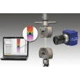
北京欧兰科技发展有限公司为您提供《核废料铜贮存罐中塑性变形定位,形变,应变检测方案(其它无损检测仪器/设备)》,该方案主要用于核能中塑性变形定位,形变,应变检测,参考标准--,《核废料铜贮存罐中塑性变形定位,形变,应变检测方案(其它无损检测仪器/设备)》用到的仪器有LaVision StrainMaster材料应变形变成像测量系统
推荐专场
相关方案
更多
该厂商其他方案
更多