


方案详情
文
With the use of this fiber-optic adaptor and the pinhole adaptor, many microscopic fluorescence measurements can be achieved. Most microscopes, including Nikon, Olympus, Zeiss, and Leica, are compatible with the Microscope Adapter.
方案详情

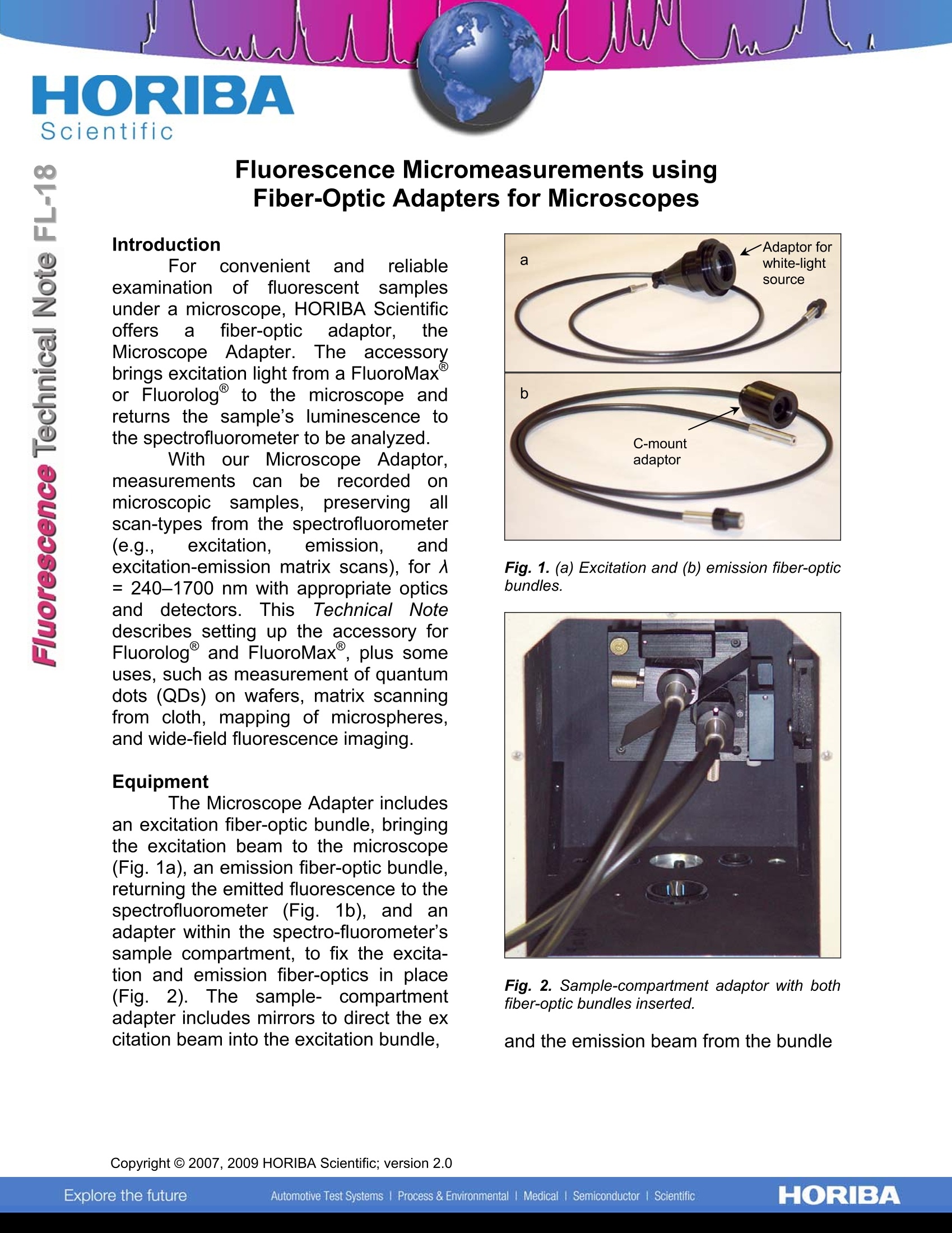
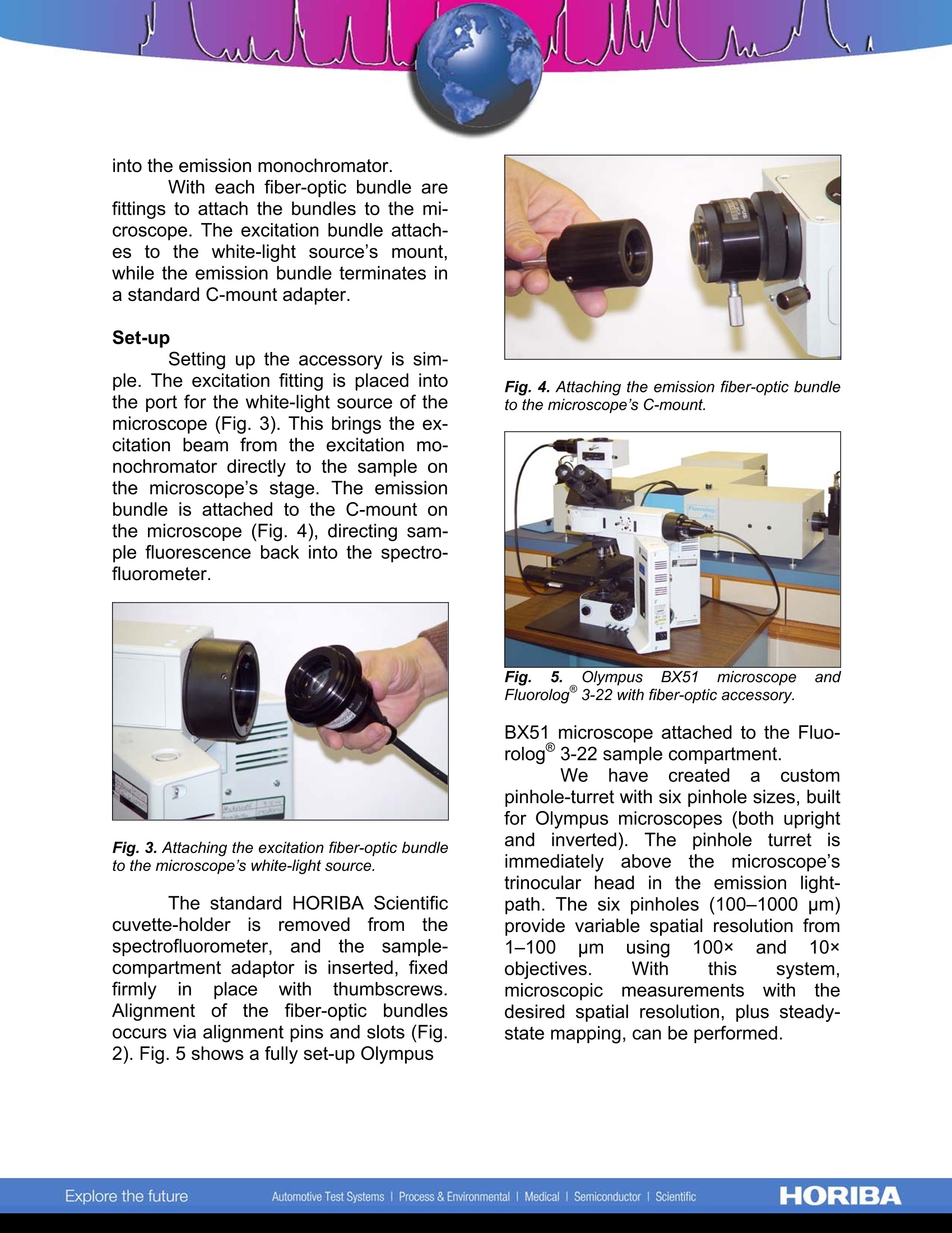
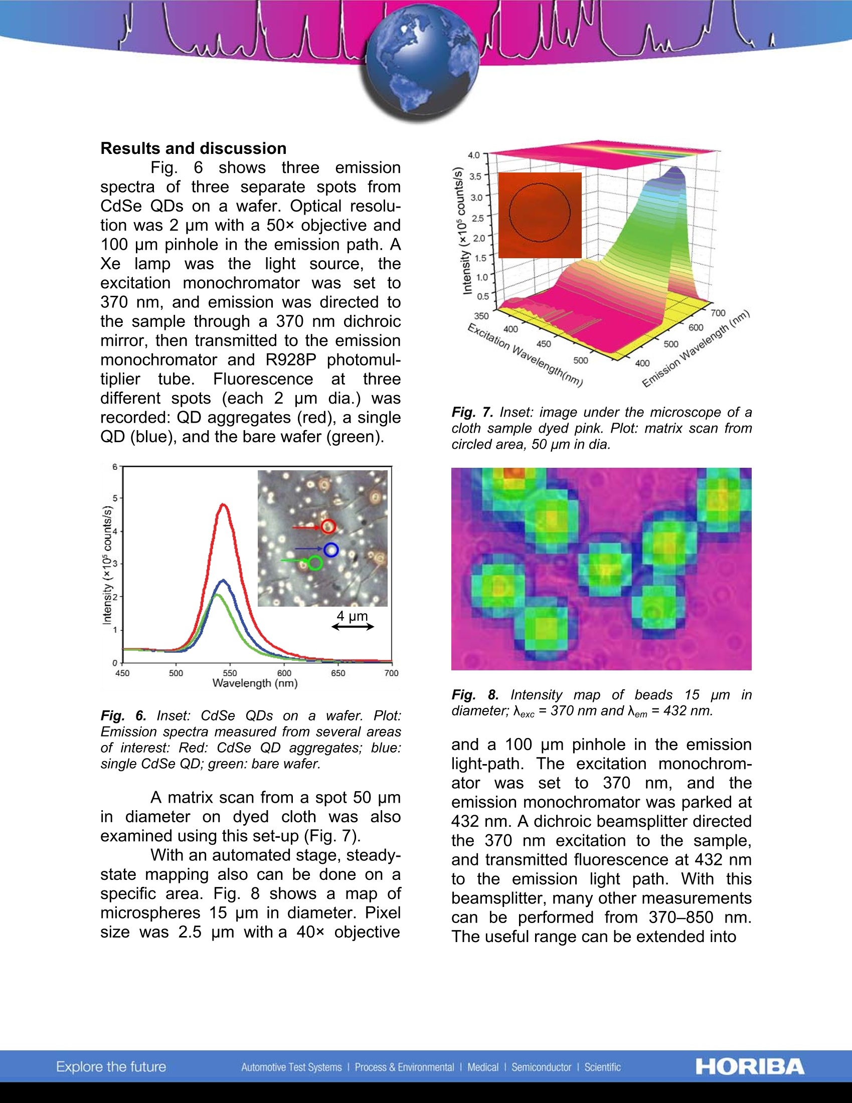
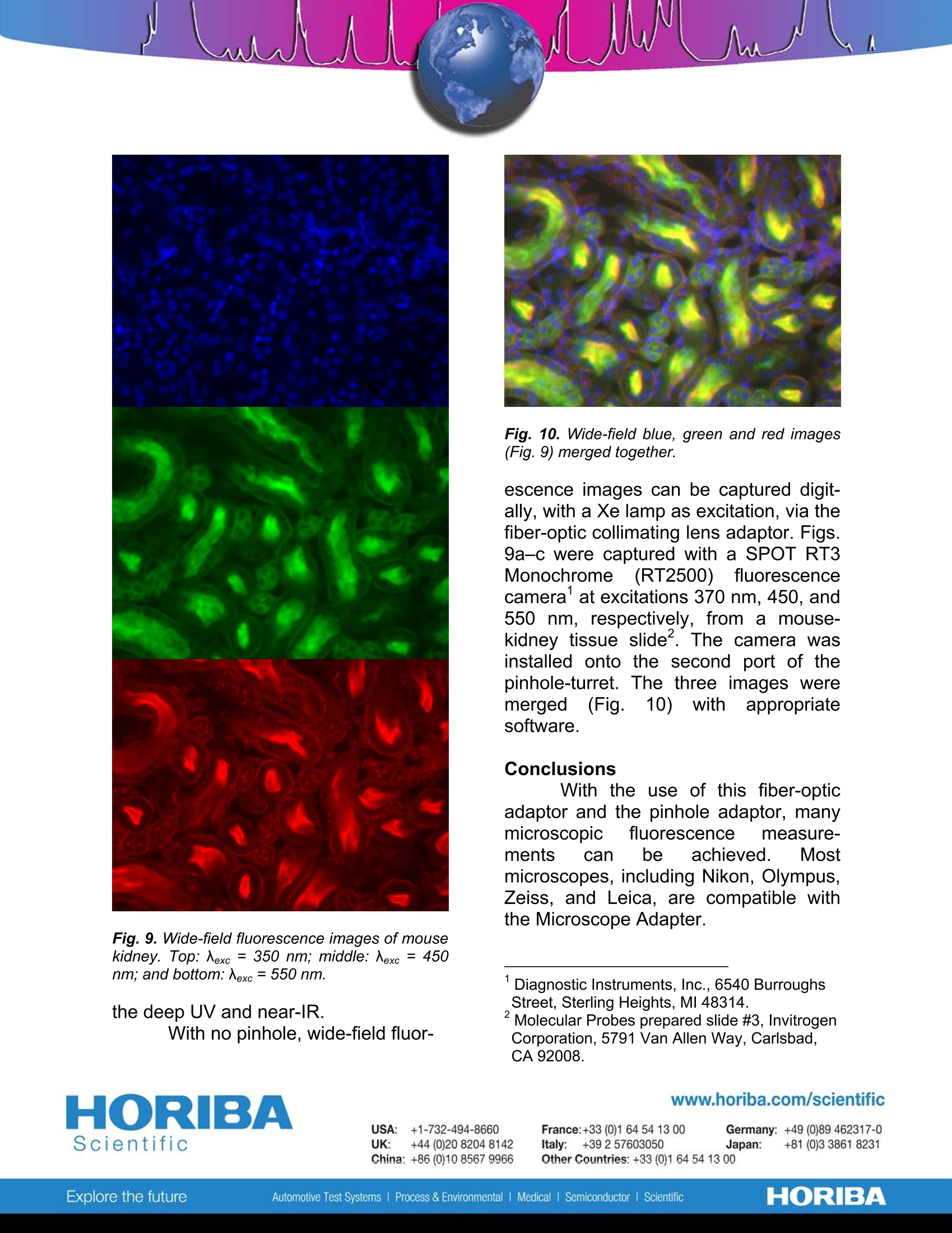
Fluorescence Micromeasurements usingFiber-Optic Adapters for Microscopes Introduction For caonvenientand reliableexamination of fluorescent samplesunder a microscope, HORIBA Scientificoffers a fiber-opticc adaptor, theMicroscope Adapter.The) accessorybrings excitation light from a FluoroMaxor Fluorolog to the microscope andreturns the sample’s luminescence tothe spectrofluorometer to be analyzed. With our·Microscope Adaptor,measurementss cann be recorded onnrfmicroscopic samples, preserving allscan-types from the spectrofluorometer(e.g., excitation. emission. andexcitation-emission matrix scans), for A= 240-1700 nm with appropriate opticsand detectors. ThisTechnicalNotedescribes setting up the accessory forFluorolog and FluoroMax, plus someuses, such as measurement of quantumdots (QDs) on wafers, matrix scanningfrom cloth, mapping of microspheres,and wide-field fluorescence imaging. Equipment The Microscope Adapter includesan excitation fiber-optic bundle, bringingthe excitation beam to the microscope(Fig. 1a), an emission fiber-optic bundle,returning the emitted fluorescence to thespectrofluorometer (Fig.1b), and anadapter within the spectro-fluorometer'ssample compartment, to fix the excita-tion and emission fiber-optics in place(Fig. 2). The sample- compartmentadapter includes mirrors to direct the excitation beam into the excitation bundle. Fig. 1. (a) Excitation and (b) emission fiber-opticbundles. Fig. 2. Sample-compartment adaptor with bothfiber-optic bundles inserted. and the emission beam from the bundle into the emission monochromator. With each fiber-optic bundle arefittings to attach the bundles to the mi-croscope. The excitation bundle attach-es to the white-light source’s mount,while the emission bundle terminates ina standard C-mount adapter. Set-up Setting up the accessory is sim-ple. The excitation fitting is placed intothe port for the white-light source of themicroscope (Fig. 3). This brings the ex-citation beam from the excitation mo-nochromator directly to the sample onthe microscope’s stage. The emissionbundle is attached to the C-mount onthe microscope (Fig.4), directing sam-ple fluorescence back into the spectro-fluorometer. Fig. 3. Attaching the excitation fiber-optic bundleto the microscope’s white-light source. The standard HORIBA Scientificcuvette-holder is; removed from thespectrofluorometer, and the sample-compartment adaptor is inserted, fixedfirmly inplace withthumbscrews.Alignment of the fiber-optic bundlesoccurs via alignment pins and slots (Fig.2). Fig.5 shows a fully set-up Olympus Fig. 4. Attaching the emission fiber-optic bundleto the microscope’s C-mount. Fluorolog@ 3-22 with fiber-optic accessory. BX51 microscope attached to the Fluo-rolog@ 3-22 sample compartment. We have createdaa custompinhole-turret with six pinhole sizes, builtfor Olympus microscopes (both uprightand inverted). The pinhole turret isimmediately above the microscope'strinocular head in the emission light-path. The six pinholes (100-1000 pm)provide variable spatial resolution from1-100 um using 100× and 10×objectives. With this system,microscopic measurements withthedesired spatial resolution, plus steady-state mapping, can be performed. Results and discussion Fig. 6showsthree emissionspectra of three separate spots fromCdSe QDs on a wafer. Optical resolu-tion was 2 pm with a 50x objective and100 um pinhole in the emission path. AXe lampwasi the light source,theexcitation monochromator was set to370 nm, and emission was directed tothe sample through a 370 nm dichroicmirror, then transmitted to the emissionmonochromator and R928P photomul-tiplier tube. Fluorescence att tthreedifferent spots (each 2 pm dia.) wasrecorded: QD aggregates (red), a singleQD (blue), and the bare wafer (green). Fig. 6. Inset: CdSe QDs on a wafer. Plot:Emission spectra measured from several areasof interest: Red: CdSe QD aggregates; blue:single CdSe QD; green: bare wafer. A matrix scan from a spot 50 pmin diameter on dyed cloth was alsoexamined using this set-up (Fig.7). With an automated stage, steady-state mapping also can be done on aspecific area. Fig. 8 shows a map ofmicrospheres 15 pm in diameter. Pixelsize was 2.55 pm with a 40×objective Fig. 7. Inset: image under the microscope of acloth sample dyed pink. Plot: matrix scan fromcircled area,50 um in dia. Fig. 8.Intensity map of beads 155umindiameter;入exc=370 nm and Nem= 432 nm. and a 100 pm pinhole in the emissionlight-path. The excitation monochrom-ator wasset to 370 nm, and theemission monochromator was parked at432 nm. A dichroic beamsplitter directedthe 370 nm excitation to the sample,and transmitted fluorescence at 432 nmto the emission light path. With thisbeamsplitter, many other measurementscan be performed from 370-850 nm.The useful range can be extended into Fig. 9. Wide-field fluorescence images of mousekidney. Top:Nexc = 350 nm; middle: Nexc=450nm; and bottom: 入exc= 550 nm. the deep UV and near-IR. With no pinhole, wide-field fluor- HORIBAScientific Fig. 10. Wide-field blue, green and red images(Fig. 9) merged together. escence images can be captured digit-ally, with a Xe lamp as excitation, via thefiber-optic collimating lens adaptor. Figs.9a-c were captured with a SPOT RT3Monochrome((RT2500))1fluorescencecamera' at excitations 370 nm, 450, and550 nm, respectively, from a mouse-kidney tissue slide. The camera wasinstalled onto the second port of thepinhole-turret. The three images weremerged(Fig. 10) withappropriatesoftware. Conclusions With the use of this fiber-opticadaptor and the pinhole adaptor, manymicroscopic fluorescence measure-ments Ccan be achieved. Mostmicroscopes, including Nikon, Olympus,Zeiss, and Leica, are compatible withthe Microscope Adapter. ( ' Diagnostic Instruments, Inc.,6540 BurroughsStreet, Sterling Heights, MI 48314. ) ( Molecular Probes prepared slide #3, Invitrogen Corporation, 5791 Van Allen Way, Carlsbad, CA 92008. ) Copyright C HORIBA Scientific; version .HORIBAExplore the futureAutomotive Test Systems Process & Environmental Medicall Medical Semiconductor lScientific HORIBAExplore the futureAutomotive Test Systems Process & Environmental Medical Semiconductor l Scientific With the use of this fiber-optic adaptor and the pinhole adaptor, many microscopic fluorescence measurements can be achieved. Most microscopes, including Nikon, Olympus, Zeiss, and Leica, are compatible with the Microscope Adapter.
确定
还剩2页未读,是否继续阅读?

产品配置单

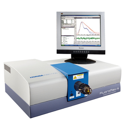
HORIBA(中国)为您提供《硒化镉量子点中发射光谱检测方案(分子荧光光谱)》,该方案主要用于其他中发射光谱检测,参考标准--,《硒化镉量子点中发射光谱检测方案(分子荧光光谱)》用到的仪器有HORIBA高灵敏一体式FluoroMax-4荧光光谱仪
推荐专场
相关方案
更多
该厂商其他方案
更多