


方案详情
文
利用LaVision的DaVis8.4软件平台构成的PIV系统测量了交叉流燃油喷射的速度场,同时测量了OH基自发辐射荧光分布,研究了交叉流燃油喷射对反应射流的影响。
方案详情

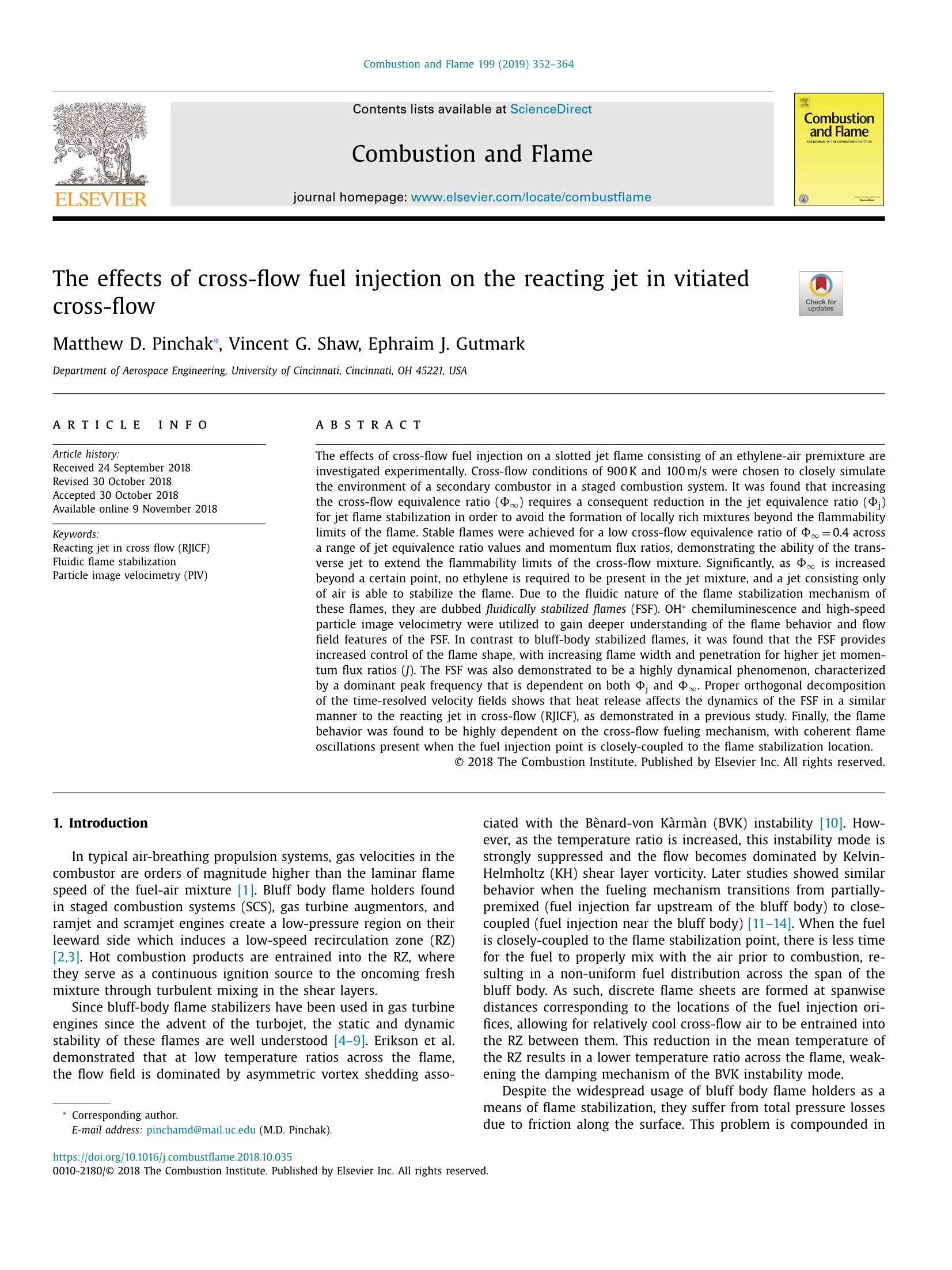
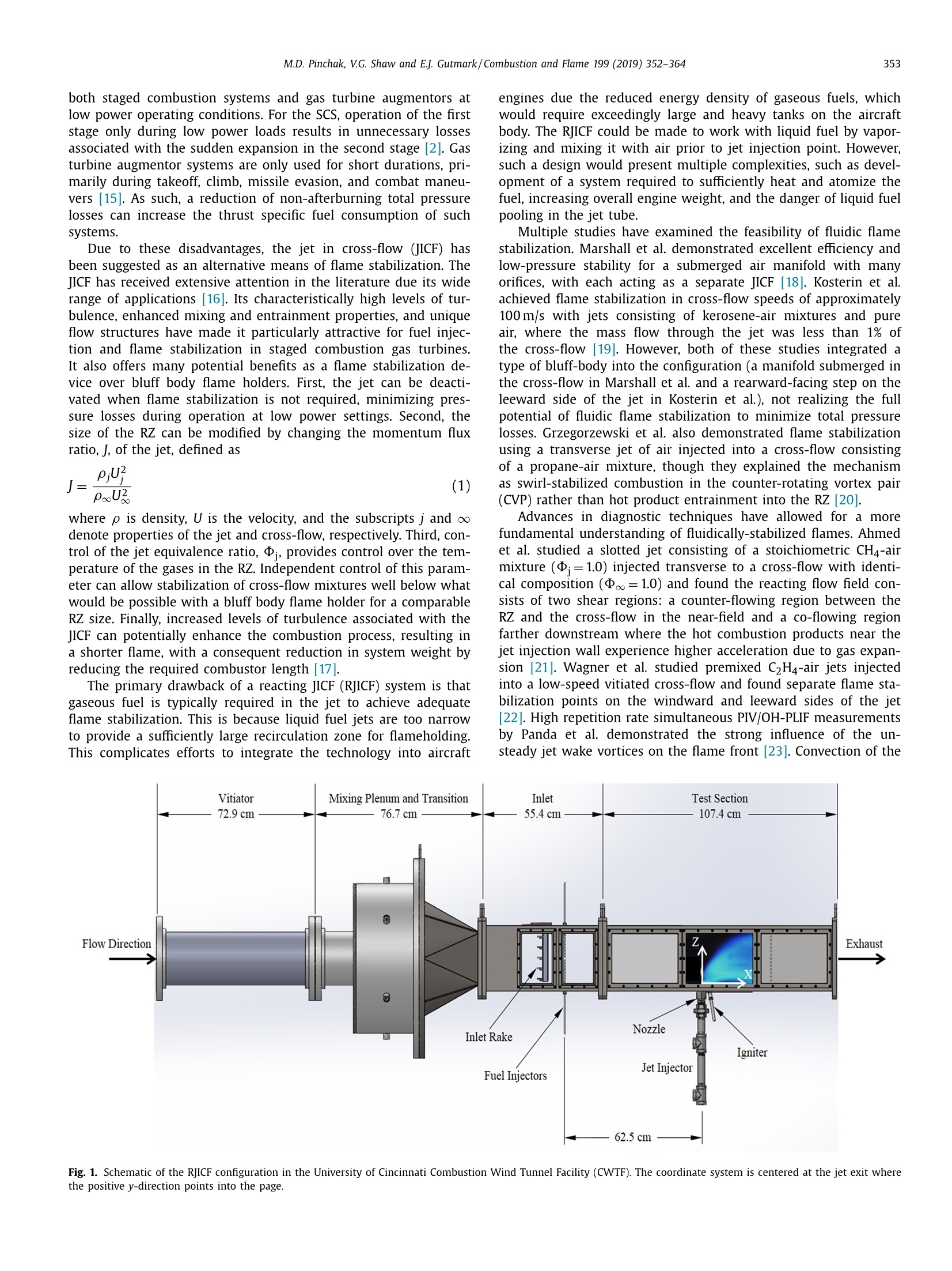
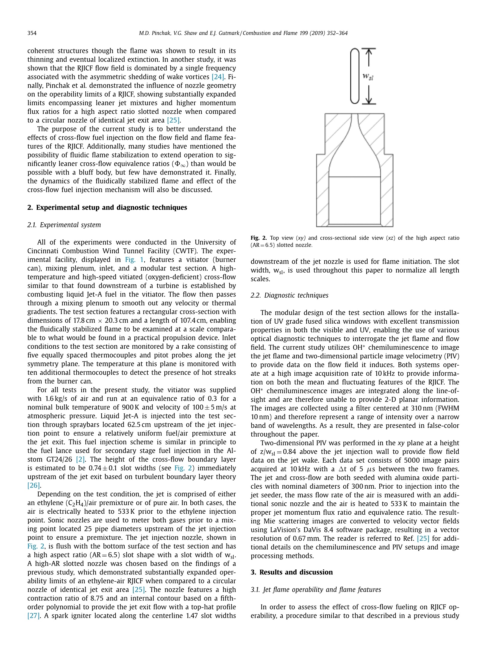
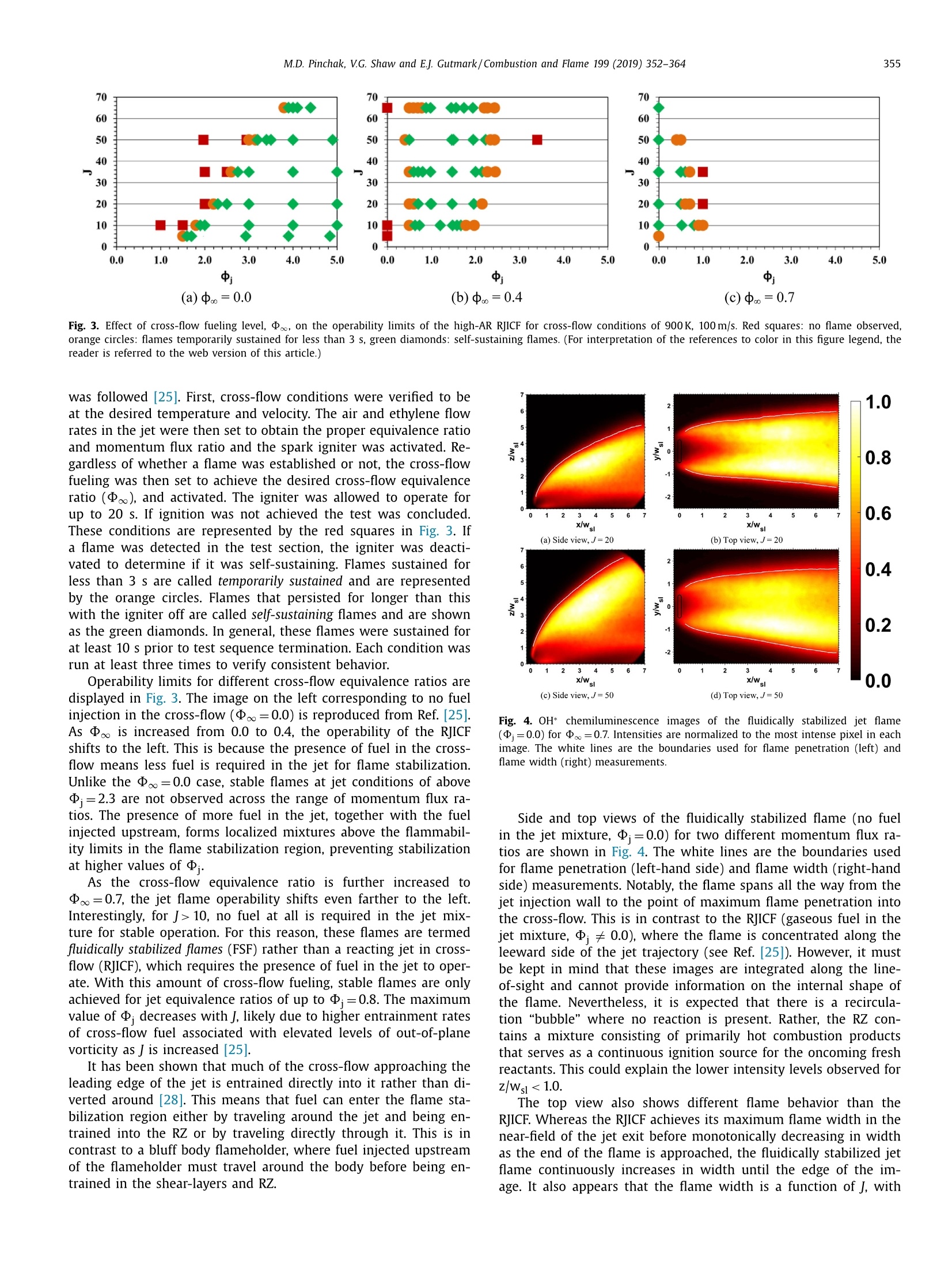
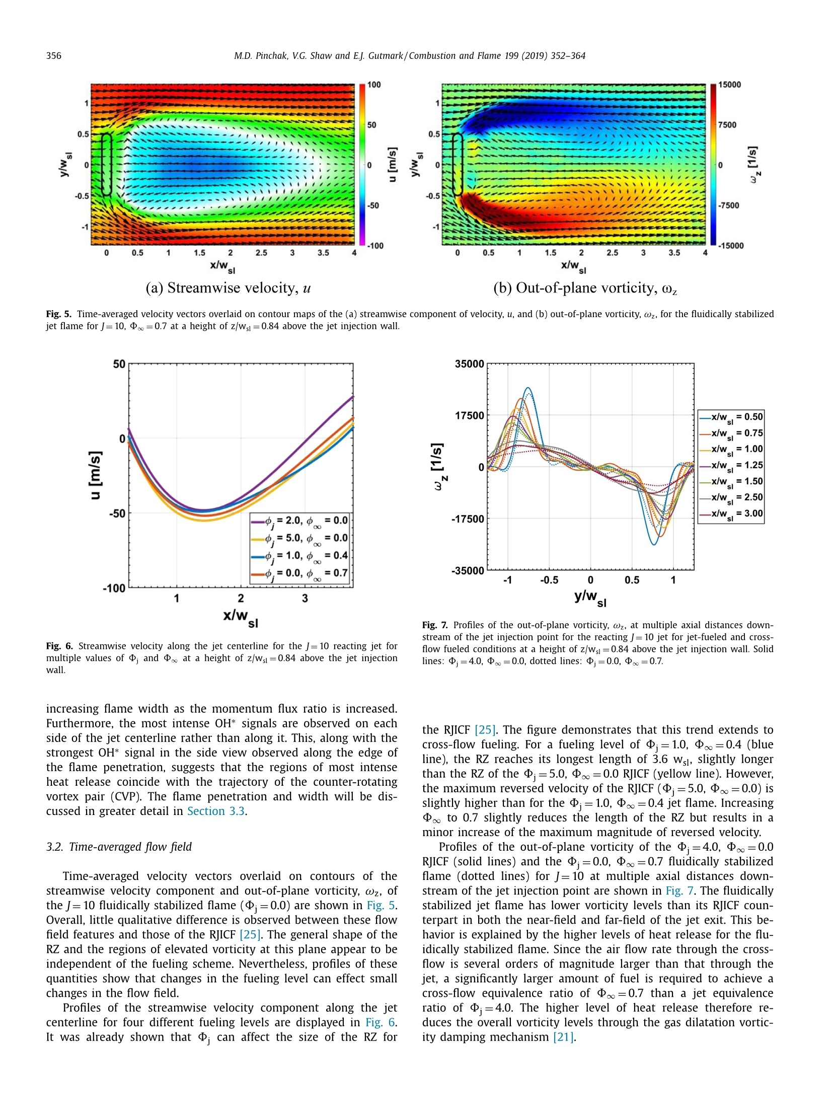
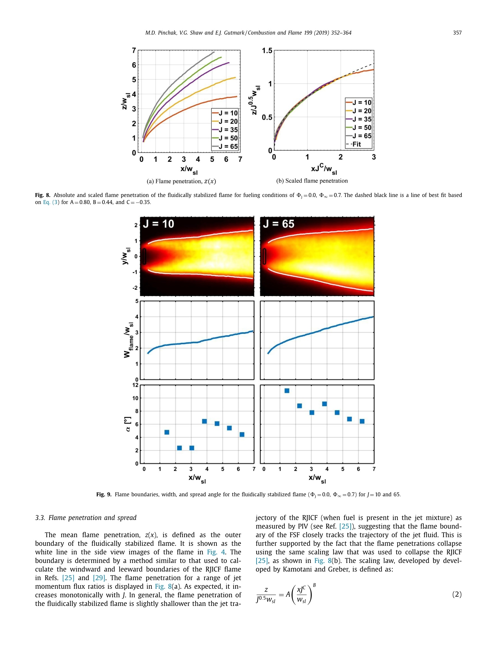
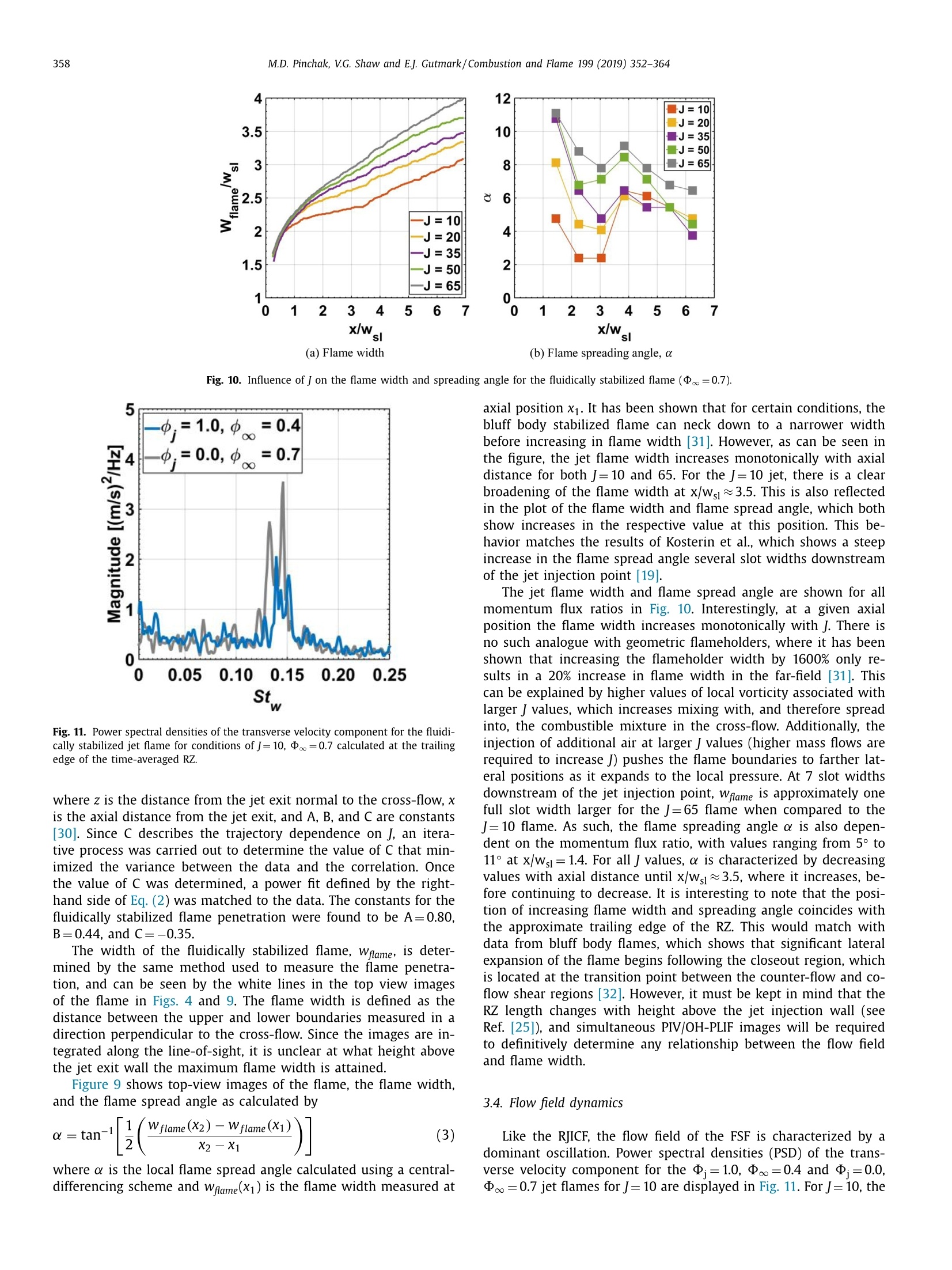
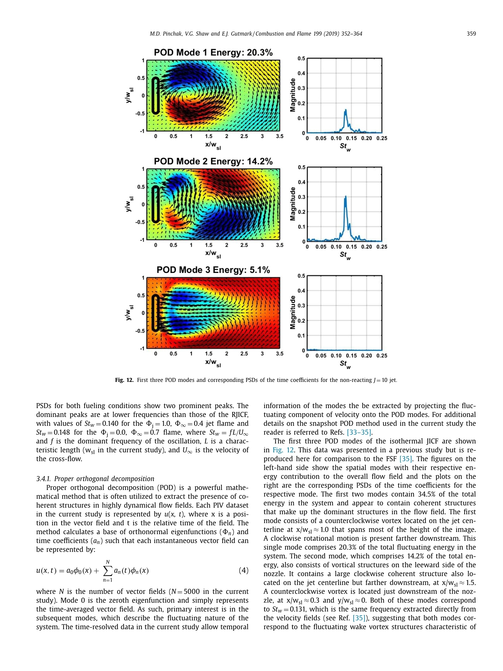
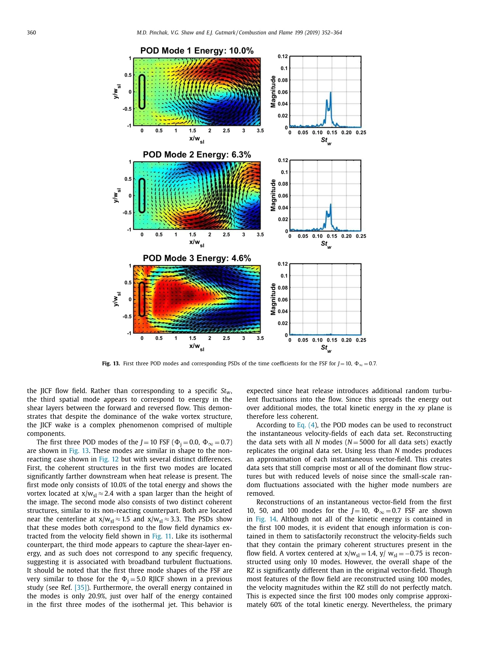
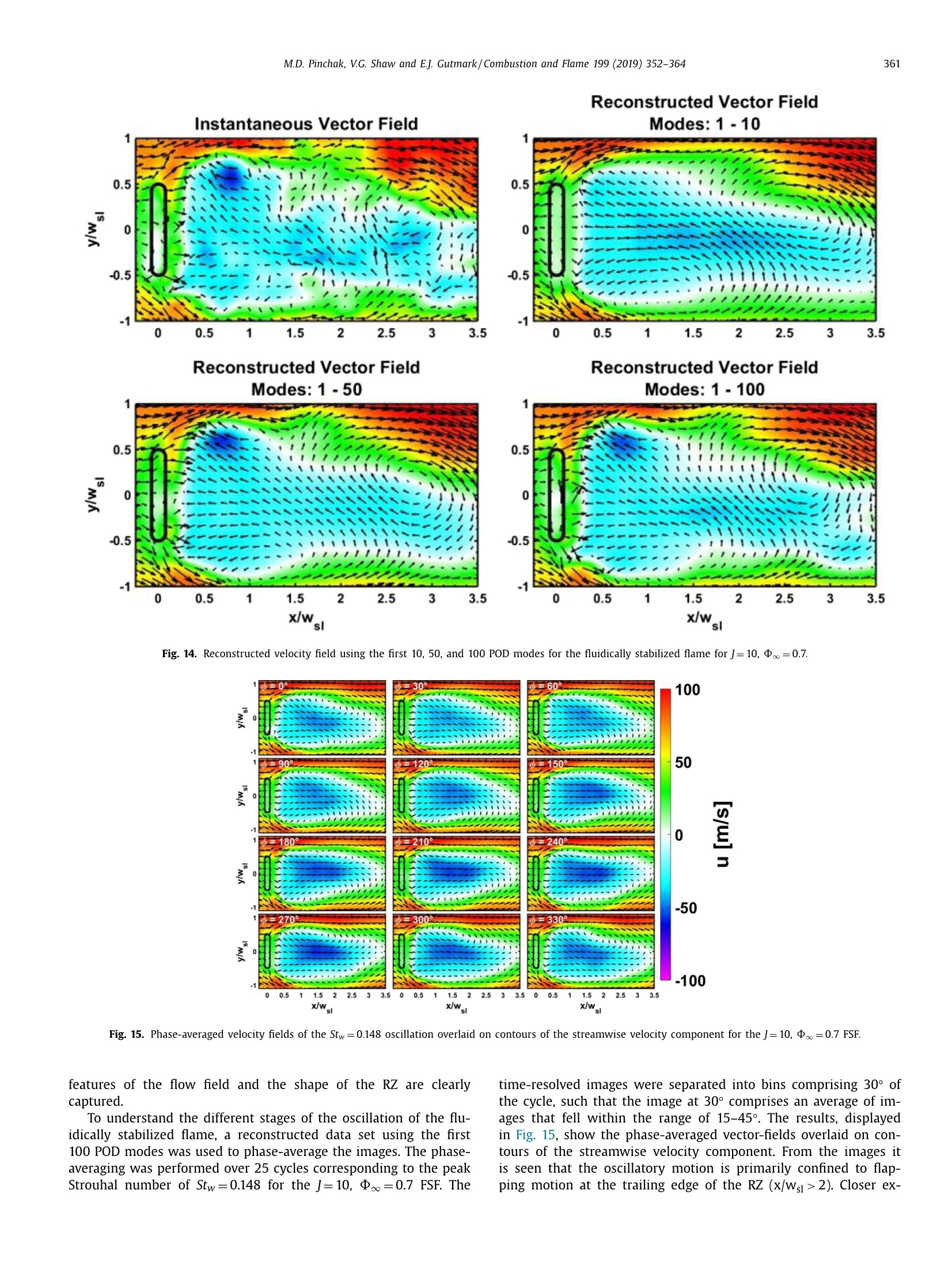
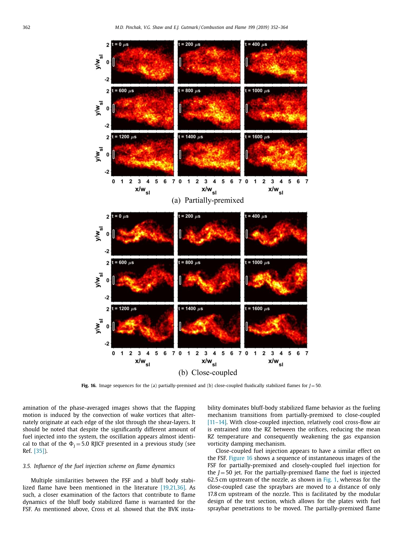
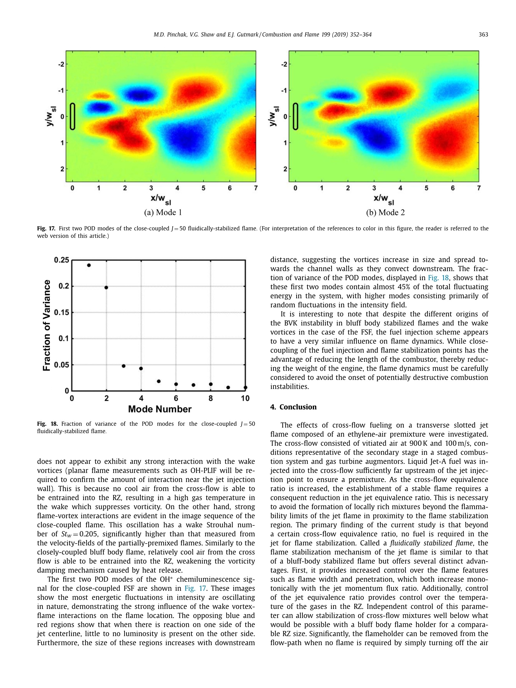
Combustion and Flame 199 (2019) 352-364Contents lists available at ScienceDirect 353M.D. Pinchak, V.G. Shaw and E.J. Gutmark/Combustion and Flame 199 (2019) 352-364 0010-2180/O 2018 The Combustion Institute. Published by Elsevier Inc. All rights reserved. Combustion and Flame ELSEVIER journal homepage: www.elsevier.com/locate/combustflame The effects of cross-flow fuel injection on the reacting jet in vitiatedcross-flow Matthew D. Pinchak*, Vincent G. Shaw, Ephraim J. Gutmark Department ofAerospace Engineering, University of Cincinnati, Cincinnati, OH 45221, USA ARTICLE INFO ABSTR ACT Article history: Received 24 September 2018Revised 30 October 2018Accepted 30 October 2018 Available online 9 November 2018 Keywords: Reacting jet in cross flow (RJICF)Fluidic flame stabilizationParticle image velocimetry (PIV) The effects of cross-flow fuel injection on a slotted jet flame consisting of an ethylene-air premixture areinvestigated experimentally. Cross-flow conditions of 900 K and 100 m/s were chosen to closely simulatethe environment of a secondary combustor in a staged combustion system. It was found that increasingthe cross-flow equivalence ratio () requires a consequent reduction in the jet equivalence ratio (D;)for jet flame stabilization in order to avoid the formation of locally rich mixtures beyond the flammabilitylimits of the flame. Stable flames were achieved for a low cross-flow equivalence ratio of 中..=0.4 acrossa range of jet equivalence ratio values and momentum flux ratios, demonstrating the ability of the trans-verse jet to extend the flammability limits of the cross-flow mixture. Significantly, as 中is increasedbeyond a certain point, no ethylene is required to be present in the jet mixture, and a jet consisting onlyof air is able to stabilize the flame. Due to the fluidic nature of the flame stabilization mechanism ofthese flames, they are dubbed fluidically stabilized flames (FSF). OH* chemiluminescence and high-speedparticle image velocimetry were utilized to gain deeper understanding of the flame behavior and flowfield features of the FSF. In contrast to bluff-body stabilized flames, it was found that the FSF providesincreased control of the flame shape, with increasing flame width and penetration for higher jet momen-tum flux ratios (). The FSF was also demonstrated to be a highly dynamical phenomenon, characterizedby a dominant peak frequency that is dependent on both D and . Proper orthogonal decompositionof the time-resolved velocity fields shows that heat release affects the dynamics of the FSF in a similarmanner to the reacting jet in cross-flow (RJICF), as demonstrated in a previous study. Finally, the flamebehavior was found to be highly dependent on the cross-flow fueling mechanism, with coherent flameoscillations present when the fuel injection point is closely-coupled to the flame stabilization location. o 2018 The Combustion Institute. Published by Elsevier Inc. All rights reserved. 1. Introduction In typical air-breathing propulsion systems, gas velocities in thecombustor are orders of magnitude higher than the laminar flamespeed of the fuel-air mixture [1]. Bluff body flame holders foundin staged combustion systems (SCS), gas turbine augmentors, andramjet and scramjet engines create a low-pressure region on theirleeward side which induces a low-speed recirculation zone (RZ)[2,3]. Hot combustion products are entrained into the RZ, wherethey serve as a continuous ignition source to the oncoming freshmixture through turbulent mixing in the shear layers. Since bluff-body flame stabilizers have been used in gas turbineengines since the advent of the turbojet, the static and dynamicstability of these flames are well understood [4-9]. Erikson et al.demonstrated that at low temperature ratios across the flame,the flow field is dominated by asymmetric vortex shedding asso- ( * Corresponding author. ) ( E-mail address: pinc h amd@mail.uc.edu ( M .D. Pinchak). ) ciated with the Benard-von Karman (BVK) instability [10]. How-ever, as the temperature ratio is increased, this instability mode isstrongly suppressed and the flow becomes dominated by Kelvin-Helmholtz (KH) shear layer vorticity. Later studies showed similarbehavior when the fueling mechanism transitions from partially-premixed (fuel injection far upstream of the bluff body) to close-coupled (fuel injection near the bluff body) [11-14]. When the fuelis closely-coupled to the flame stabilization point, there is less timefor the fuel to properly mix with the air prior to combustion, re-sulting in a non-uniform fuel distribution across the span of thebluff body. As such, discrete flame sheets are formed at spanwisedistances corresponding to the locations of the fuel injection ori-fices, allowing for relatively cool cross-flow air to be entrained intothe RZ between them. This reduction in the mean temperature ofthe RZ results in a lower temperature ratio across the flame, weak-ening the damping mechanism of the BVK instability mode. Despite the widespread usage of bluff body flame holders as ameans of flame stabilization, they suffer from total pressure lossesdue to friction along the surface. This problem is compounded in both staged combustion systems and gas turbine augmentors atlow power operating conditions. For the SCS, operation of the firststage only during low power loads results in unnecessary lossesassociated with the sudden expansion in the second stage [2]. Gasturbine augmentor systems are only used for short durations, pri-marily during takeoff,climb, missile evasion, and combat maneu-vers [15]. As such, a reduction of non-afterburning total pressurelosses can increase the thrust specific fuel consumption of suchsystems. Due to these disadvantages, the jet in cross-flow (JICF) hasbeen suggested as an alternative means of flame stabilization. TheJICF has received extensive attention in the literature due its widerange of applications [16]. Its characteristically high levels of tur-bulence, enhanced mixing and entrainment properties, and uniqueflow structures have made it particularly attractive for fuel injec-tion and flame stabilization in staged combustion gas turbines.It also offers many potential benefits as a flame stabilization de-vice over bluff body flame holders. First, the jet can be deacti-vated when flame stabilization is not required, minimizing pres-sure losses during operation at low power settings. Second, thesize of the RZ can be modified by changing the momentum fluxratio,J, of the jet, defined as where p is density, U is the velocity, and the subscripts j and odenote properties of the jet and cross-flow, respectively. Third, con-trol ofthe jet equivalence ratio, D,provides control over the tem-perature of the gases in the RZ. Independent control of this param-eter can allow stabilization of cross-flow mixtures well below whatwould be possible with a bluff body flame holder for a comparableRZ size. Finally, increased levels of turbulence associated with theJICF can potentially enhance the combustion process, resulting ina shorter flame, with a consequent reduction in system weight byreducing the required combustor length [17]. The primary drawback of a reacting JICF (RJICF) system is thatgaseous fuel is typically required in the jet to achieve adequateflame stabilization. This is because liquid fuel jets are too narrowto provide a sufficiently large recirculation zone for flameholding.This complicates efforts to integrate the technology into aircraft engines due the reduced energy density of gaseous fuels, whichwould require exceedingly large and heavy tanks on the aircraftbody. The RJICF could be made to work with liquid fuel by vapor-izing and mixing it with air prior to jet injection point. However,such a design would present multiple complexities, such as devel-opment of a system required to sufficiently heat and atomize thefuel, increasing overall engine weight, and the danger of liquid fuelpooling in the jet tube. Multiple studies have examined the feasibility of fluidic flamestabilization. Marshall et al. demonstrated excellent efficiency andlow-pressure stability for a submerged air manifold with manyorifices, with each acting as a separate JICF [18]. Kosterin et al.achieved flame stabilization in cross-flow speeds of approximately100 m/s with jets consisting of kerosene-air mixtures and pureair, where the mass flow through the jet was less than 1% ofthe cross-flow [19]. However, both of these studies integrated atype of bluff-body into the configuration (a manifold submerged inthe cross-flow in Marshall et al. and a rearward-facing step on theleeward side of the jet in Kosterin et al.), not realizing the fullpotential of fluidic flame stabilization to minimize total pressurelosses. Grzegorzewski et al. also demonstrated flame stabilizationusing a transverse jet of air injected into a cross-flow consistingof a propane-air mixture, though they explained the mechanismas swirl-stabilized combustion in the counter-rotating vortex pair(CVP) rather than hot product entrainment into the RZ [20]. Advances in diagnostic techniques have allowed for a morefundamental understanding of fluidically-stabilized flames. Ahmedet al. studied a slotted jet consisting of a stoichiometric CH4-airmixture(D;=1.0) injected transverse to a cross-flow with identi-cal composition (中。=1.0) and found the reacting flow field con-sists of two shear regions: a counter-flowing region between theRZ and the cross-flow in the near-field and a co-flowing regionfarther downstream where the hot combustion products near thejet injection wall experience higher acceleration due to gas expan-sion [21]. Wagner et al. studied premixed C2H4-air jets injectedinto a low-speed vitiated cross-flow and found separate flame sta-bilization points on the windward and leeward sides of the jet[22]. High repetition rate simultaneous PIV/OH-PLIF measurementsby Panda et al. demonstrated the strong influence of the un-steady jet wake vortices on the flame front [23]. Convection of the coherent structures though the flame was shown to result in itsthinning and eventual localized extinction. In another study, it wasshown that the RJICF flow field is dominated by a single frequencyassociated with the asymmetric shedding of wake vortices [24]. Fi-nally, Pinchak et al. demonstrated the influence of nozzle geometryon the operability limits of a RJICF, showing substantially expandedlimits encompassing leaner jet mixtures and higher momentumflux ratios for a high aspect ratio slotted nozzle when comparedto a circular nozzle of identical jet exit area [25]. The purpose of the current study is to better understand theeffects of cross-flow fuel injection on the flow field and flame fea-tures of the RJICF. Additionally, many studies have mentioned thepossibility of fluidic flame stabilization to extend operation to sig-nificantly leaner cross-flow equivalence ratios (。) than would bepossible with a bluff body, but few have demonstrated it. Finally,the dynamics of the fluidically stabilized flame and effect of thecross-flow fuel injection mechanism will also be discussed. 2. Experimental setup and diagnostic techniques 2.1. Experimental system All of the experiments were conducted in the University ofCincinnati Combustion Wind Tunnel Facility (CWTF). The exper-imental facility, displayed in Fig. 1, features a vitiator (burnercan), mixing plenum, inlet, and a modular test section. A high-temperature and high-speed vitiated (oxygen-deficient) cross-flowsimilar to that found downstream of a turbine is established bycombusting liquid Jet-A fuel in the vitiator. The flow then passesthrough a mixing plenum to smooth out any velocity or thermalgradients. The test section features a rectangular cross-section withdimensions of 17.8 cm x 20.3 cm and a length of 107.4cm, enablingthe fluidically stabilized flame to be examined at a scale compara-ble to what would be found in a practical propulsion device. Inletconditions to the test section are monitored by a rake consisting offive equally spaced thermocouples and pitot probes along the jetsymmetry plane. The temperature at this plane is monitored withten additional thermocouples to detect the presence of hot streaksfrom the burner can. For all tests in the present study, the vitiator was suppliedwith 1.6kg/s of air and run at an equivalence ratio of 0.3 for anominal bulk temperature of 900K and velocity of 100±5 m/s atatmospheric pressure. Liquid Jet-A is injected into the test sec-tion through spraybars located 62.5 cm upstream of the jet injec-tion point to ensure a relatively uniform fuel/air premixture atthe jet exit. This fuel injection scheme is similar in principle tothe fuel lance used for secondary stage fuel injection in the Al-stom GT24/26 [2]. The height of the cross-flow boundary layeris estimated to be 0.74±0.1 slot widths (see Fig. 2) immediatelyupstream of the jet exit based on turbulent boundary layer theory[26]. Depending on the test condition, the jet is comprised of eitheran ethylene (C2H4)/air premixture or of pure air. In both cases, theair is electrically heated to 533K prior to the ethylene injectionpoint. Sonic nozzles are used to meter both gases prior to a mix-ing point located 25 pipe diameters upstream of the jet injectionpoint to ensure a premixture. The jet injection nozzle, shown inFig. 2, is flush with the bottom surface of the test section and hasa high aspect ratio (AR=6.5) slot shape with a slot width of ws.A high-AR slotted nozzle was chosen based on the findings of aprevious study, which demonstrated substantially expanded oper-ability limits of an ethylene-air RJICF when compared to a circularnozzle of identical jet exit area [25]. The nozzle features a highcontraction ratio of 8.75 and an internal contour based on a fifth-order polynomial to provide the jet exit flow with a top-hat profile[27]. A spark igniter located along the centerline 1.47 slot widths 1个 Wsi Fig. 2. Top view (xy) and cross-sectional side view (xz) of the high aspect ratio(AR=6.5) slotted nozzle. downstream of the jet nozzle is used for flame initiation. The slotwidth, ws, is used throughout this paper to normalize all lengthscales. 2.2. Diagnostic techniques The modular design of the test section allows for the installa-tion of UV grade fused silica windows with excellent transmissionproperties in both the visible and UV, enabling the use of variousoptical diagnostic techniques to interrogate the jet flame and flowfield. The current study utilizes OH* chemiluminescence to imagethe jet flame and two-dimensional particle image velocimetry (PIV)to provide data on the flow field it induces. Both systems oper-ate at a high image acquisition rate of 10 kHz to provide informa-tion on both the mean and fluctuating features of the RJICF. TheOH* chemiluminescence images are integrated along the line-of-sight and are therefore unable to provide 2-D planar information.The images are collected using a filter centered at 310nm (FWHM10 nm) and therefore represent a range of intensity over a narrowband of wavelengths. As a result, they are presented in false-colorthroughout the paper. Two-dimensional PIV was performed in the xy plane at a heightof z/Wsl=0.84 above the jet injection wall to provide flow fielddata on the jet wake. Each data set consists of 5000 image pairsacquired at 10kHz with a At of 5 us between the two frames.The jet and cross-flow are both seeded with alumina oxide parti-cles with nominal diameters of 300 nm. Prior to injection into thejet seeder, the mass flow rate of the air is measured with an addi-tional sonic nozzle and the air is heated to 533 K to maintain theproper jet momentum flux ratio and equivalence ratio. The result-ing Mie scattering images are converted to velocity vector fieldsusing LaVision’s DaVis 8.4 software package, resulting in a vectorresolution of 0.67 mm. The reader is referred to Ref.[25] for addi-tional details on the chemiluminescence and PIV setups and imageprocessing methods. 3. Results and discussion 3.1. Jet flame operability and flame features In order to assess the effect of cross-flow fueling on RJICF op-erability, a procedure similar to that described in a previous study (a)中..=0.0 (b)中..=0.4 (c)中..=0.7 was followed [25]. First, cross-flow conditions were verified to beat the desired temperature and velocity. The air and ethylene flowrates in the jet were then set to obtain the proper equivalence ratioand momentum flux ratio and the spark igniter was activated. Re-gardless of whether a flame was established or not, the cross-flowfueling was then set to achieve the desired cross-flow equivalenceratio (。), and activated. The igniter was allowed to operate forup to 20 s. If ignition was not achieved the test was concluded.These conditions are represented by the red squares in Fig. 3. Ifa flame was detected in the test section, the igniter was deacti-vated to determine if it was self-sustaining. Flames sustained forless than 3 s are called temporarily sustained and are representedby the orange circles. Flames that persisted for longer than thiswith the igniter off are called self-sustaining flames and are shownas the green diamonds. In general, these flames were sustained forat least 10 s prior to test sequence termination. Each condition wasrun at least three times to verify consistent behavior. Operability limits for different cross-flow equivalence ratios aredisplayed in Fig. 3. The image on the left corresponding to no fuelinjection in the cross-flow (。.=0.0) is reproduced from Ref. [25].As P.。 is increased from 0.0 to 0.4, the operability of the RJICFshifts to the left. This is because the presence of fuel in the cross-flow means less fuel is required in the jet for flame stabilization.Unlike the。=0.0 case, stable flames at jet conditions of aboveD=2.3 are not observed across the range of momentum flux ra-tios. The presence of more fuel in the jet, together with the fuelinjected upstream, forms localized mixtures above the flammabil-ity limits in the flame stabilization region, preventing stabilizationat higher values of . As the cross-flow equivalence ratio is further increased to.=0.7, the jet flame operability shifts even farther to the left.Interestingly, for J> 10, no fuel at all is required in the jet mix-ture for stable operation. For this reason, these flames are termedfluidically stabilized flames (FSF) rather than a reacting jet in cross-flow (RJICF), which requires the presence of fuel in the jet to oper-ate. With this amount of cross-flow fueling, stable flames are onlyachieved for jet equivalence ratios of up to D=0.8. The maximumvalue of D. decreases with J, likely due to higher entrainment ratesof cross-flow fuel associated with elevated levels of out-of-planevorticity as J is increased [25]. It has been shown that much of the cross-flow approaching theleading edge of the jet is entrained directly into it rather than di-verted around [281. This means that fuel can enter the flame sta-bilization region either by traveling around the jet and being en-trained into the RZ or by traveling directly through it. This is incontrast to a bluff body flameholder, where fuel injected upstreamof the flameholder must travel around the body before being en-trained in the shear-layers and RZ. Fig. 4. OH* chemiluminescence images of the fluidically stabilized jet flame(;=0.0) for 中。.=0.7. Intensities are normalized to the most intense pixel in eachimage. The white lines are the boundaries used for flame penetration (left) andflame width (right) measurements. Side and top views of the fluidically stabilized flame (no fuelin the jet mixture, D;=0.0) for two different momentum flux ra-tios are shown in Fig. 4. The white lines are the boundaries usedfor flame penetration (left-hand side) and flame width (right-handside) measurements. Notably, the flame spans all the way from thejet injection wall to the point of maximum flame penetration intothe cross-flow. This is in contrast to the RJICF (gaseous fuel in thejet mixture, D;/0.0), where the flame is concentrated along theleeward side of the jet trajectory (see Ref. [25]). However, it mustbe kept in mind that these images are integrated along the line-of-sight and cannot provide information on the internal shape ofthe flame. Nevertheless, it is expected that there is a recircula-tion“bubble"where no reaction is present. Rather, the RZ con-tains a mixture consisting of primarily hot combustion productsthat serves as a continuous ignition source for the oncoming freshreactants. This could explain the lower intensity levels observed forz/wsl<1.0. The top view also shows different flame behavior than theRJICF. Whereas the RJICF achieves its maximum flame width in thenear-field of the jet exit before monotonically decreasing in widthas the end of the flame is approached, the fluidically stabilized jetflame continuously increases in width until the edge of the im-age. It also appears that the flame width is a function of J, with -100 x/W (a) Streamwise velocity, u Fig. 6. Streamwise velocity along the jet centerline for the J=10 reacting jet formultiple values of D and d. at a height of z/wsl=0.84 above the jet injectionwall. increasing flame width as the momentum flux ratio is increased.Furthermore, the most intense OH* signals are observed on eachside of the jet centerline rather than along it. This, along with thestrongest OH* signal in the side view observed along the edge ofthe flame penetration, suggests that the regions of most intenseheat release coincide with the trajectory of the counter-rotatingvortex pair (CVP). The flame penetration and width will be dis-cussed in greater detail in Section 3.3. 3.2. Time-averaged flow field Time-averaged velocity vectors overlaid on contours of thestreamwise velocity component and out-of-plane vorticity, ωz, ofthe J=10 fluidically stabilized flame (j=0.0) are shown in Fig.5.Overall, little qualitative difference is observed between these flowfield features and those of the RJICF [25]. The general shape of theRZ and the regions of elevated vorticity at this plane appear to beindependent of the fueling scheme. Nevertheless, profiles of thesequantities show that changes in the fueling level can effect smallchanges in the flow field. Profiles of the streamwise velocity component along the jetcenterline for four different fueling levels are displayed in Fig. 6.It was already shown thatD. can affect the size of the RZ for 3 (b)Out-of-plane vorticity,ωz Fig. 5. Time-averaged velocity vectors overlaid on contour maps of the (a) streamwise component of velocity, u, and (b) out-of-plane vorticity,ωz, for the fluidically stabilizedjet flame for J=10, .=0.7 at a height ofz/wsi=0.84 above the jet injection wall. Fig. 7. Profiles of the out-of-plane vorticity, ωz, at multiple axial distances down-stream of the jet injection point for the reacting J=10 jet for jet-fueled and cross-flow fueled conditions at a height of z/wsi=0.84 above the jet injection wall.Solidlines: D=4.0, 中.=0.0, dotted lines: D=0.0, 中..=0.7. the RJICF[25]. The figure demonstrates that this trend extends tocross-flow fueling. For a fueling level of =1.0, 。=0.4 (blueline), the RZ reaches its longest length of 3.6 Wsl, slightly longerthan the RZ of the D=5.0, 中。=0.0 RJICF (yellow line). However,the maximum reversed velocity of the RJICF (D;=5.0,P。=0.0) isslightly higher than for the D=1.0,.=0.4 jet flame. Increasing中.。 to 0.7 slightly reduces the length of the RZ but results in aminor increase of the maximum magnitude of reversed velocity. Profiles of the out-of-plane vorticity of the D=4.0, 中。=0.0RJICF (solid lines) and the D;=0.0,.=0.7 fluidically stabilizedflame (dotted lines) for J= 10 at multiple axial distances down-stream of the jet injection point are shown in Fig. 7. The fluidicallystabilized jet flame has lower vorticity levels than its RJICF coun-terpart in both the near-field and far-field of the jet exit. This be-havior is explained by the higher levels of heat release for the flu-idically stabilized flame. Since the air flow rate through the cross-flow is several orders of magnitude larger than that through thejet, a significantly larger amount of fuel is required to achieve across-flow equivalence ratio of d.=0.7 than a jet equivalenceratio of d=4.0. The higher level of heat release therefore re-duces the overall vorticity levels through the gas dilatation vortic-ity damping mechanism [21]. (a) Flame penetration,z(x) (b) Scaled flame penetration Fig. 8. Absolute and scaled flame penetration of the fluidically stabilized flame for fueling conditions of d=0.0, 中。=0.7. The dashed black line is a line of best fit basedon Eq. (3) for A=0.80, B=0.44, and C=-0.35. Fig. 9. Flame boundaries, width, and spread angle for the fluidically stabilized flame (D;=0.0,.=0.7) for J= 10 and 65. 3.3. Flame penetration and spread The mean flame penetration, z(x), is defined as the outerboundary of the fluidically stabilized flame. It is shown as thewhite line in the side view images of the flame in Fig. 4. Theboundary is determined by a method similar to that used to cal-culate the windward and leeward boundaries of the RJICF flamein Refs. [25] and [29]. The flame penetration for a range of jetmomentum flux ratios is displayed in Fig. 8(a). As expected, it in-creases monotonically with J. In general, the flame penetration ofthe fluidically stabilized flame is slightly shallower than the jet tra- jectory of the RJICF (when fuel is present in the jet mixture) asmeasured by PlV (see Ref.[25]), suggesting that the flame bound-ary of the FSF closely tracks the trajectory of the jet fluid. This isfurther supported by the fact that the flame penetrations collapseusing the same scaling law that was used to collapse the RJICF[25], as shown in Fig.8(b).The scaling law, developed by devel-oped by Kamotani and Greber, is defined as: (a) Flame width (b) Flame spreading angle, α Fig. 10. Influence of J on the flame width and spreading angle for the fluidically stabilized flame (=0.7). Fig. 11. Power spectral densities of the transverse velocity component for the fluidi-cally stabilized jet flame for conditions of J=10, .。=0.7 calculated at the trailingedge of the time-averaged RZ. where z is the distance from the jet exit normal to the cross-flow, xis the axial distance from the jet exit, and A, B, and C are constants[30]. Since C describes the trajectory dependence on J, an itera-tive process was carried out to determine the value of C that min-imized the variance between the data and the correlation. Oncethe value of C was determined, a power fit defined by the right-hand side of Eq. (2) was matched to the data. The constants for thefluidically stabilized flame penetration were found to be A=0.80,B=0.44, and C=-0.35. The width of the fluidically stabilized flame, Wlame, is deter-mined by the same method used to measure the flame penetra-tion, and can be seen by the white lines in the top view imagesof the flame in Figs. 4 and 9. The flame width is defined as thedistance between the upper and lower boundaries measured in adirection perpendicular to the cross-flow. Since the images are in-tegrated along the line-of-sight, it is unclear at what height abovethe jet exit wall the maximum flame width is attained. Figure 9 shows top-view images of the flame, the flame width,and the flame spread angle as calculated by where a is the local flame spread angle calculated using a central-differencing scheme and WRame(x1) is the flame width measured at axial position x1. It has been shown that for certain conditions, thebluff body stabilized flame can neck down to a narrower widthbefore increasing in flame width [31]. However, as can be seen inthe figure, the jet flame width increases monotonically with axialdistance for both J=10 and 65. For the J=10 jet, there is a clearbroadening of the flame width at x/ws~3.5. This is also reflectedin the plot of the flame width and flame spread angle, which bothshow increases in the respective value at this position. This be-havior matches the results of Kosterin et al., which shows a steepincrease in the flame spread angle several slot widths downstreamof the jet injection point [19]. The jet flame width and flame spread angle are shown for allmomentum flux ratios in Fig. 10. Interestingly, at a given axialposition the flame width increases monotonically with J. There isno such analogue with geometric flameholders, where it has beenshown that increasing the flameholder width by 1600% only re-sults in a 20% increase in flame width in the far-field [31]. Thiscan be explained by higher values of local vorticity associated withlarger J values, which increases mixing with, and therefore spreadinto, the combustible mixture in the cross-flow. Additionally, theinjection of additional air at larger J values (higher mass flows arerequired to increase J) pushes the flame boundaries to farther lat-eral positions as it expands to the local pressure. At 7 slot widthsdownstream of the jet injection point, Wrlame is approximately onefull slot width larger for the J=65 flame when compared to theJ=10 flame. As such, the flame spreading angle a is also depen-dent on the momentum flux ratio, with values ranging from 5° to11°at x/Ws=1.4. For all J values, a is characterized by decreasingvalues with axial distance until x/ws~3.5, where it increases, be-fore continuing to decrease.It is interesting to note that the posi-tion of increasing flame width and spreading angle coincides withthe approximate trailing edge of the RZ. This would match withdata from bluff body flames, which shows that significant lateralexpansion of the flame begins following the closeout region, whichis located at the transition point between the counter-flow and co-flow shear regions [32]. However, it must be kept in mind that theRZ length changes with height above the jet injection wall (seeRef. [25]), and simultaneous PIV/OH-PLIF images will be requiredto definitively determine any relationship between the flow fieldand flame width. 3.4. Flow field dynamics Like the RJICF, the flow field of the FSF is characterized by adominant oscillation. Power spectral densities (PSD) of the trans-verse velocity component for the D=1.0, d。=0.4 and d=0.0,。.=0.7 jet flames for J=10 are displayed in Fig. 11. ForJ=10, the PSDs for both fueling conditions show two prominent peaks. Thedominant peaks are at lower frequencies than those of the RJICF,with values of Stw=0.140 for the D.=1.0, .=0.4 jet flame andStw=0.148 for the D=0.0, 中。=0.7 flame, where Stw =fL/U.and f is the dominant frequency of the oscillation, L is a charac-teristic length (Ws in the current study), and U.。 is the velocity ofthe cross-flow. 3.4.1. Proper orthogonal decomposition Proper orthogonal decomposition (POD) is a powerful mathe-matical method that is often utilized to extract the presence of co-herent structures in highly dynamical flow fields. Each PIV datasetin the current study is represented by u(x, t), where x is a posi-tion in the vector field and t is the relative time of the field. Themethod calculates a base of orthonormal eigenfunctions (n) andtime coefficients (an) such that each instantaneous vector field canbe represented by: where N is the number of vector fields (N=5000 in the currentstudy). Mode 0 is the zeroth eigenfunction and simply representsthe time-averaged vector field. As such, primary interest is in thesubsequent modes, which describe the fluctuating nature of thesystem. The time-resolved data in the current study allow temporal information of the modes the be extracted by projecting the fluc-tuating component of velocity onto the POD modes. For additionaldetails on the snapshot POD method used in the current study thereader is referred to Refs. [33-351. The first three POD modes of the isothermal JICF are shownin Fig. 12. This data was presented in a previous study but is re-produced here for comparison to the FSF [35].The figures on theleft-hand side show the spatial modes with their respective en-ergy contribution to the overall flow field and the plots on theright are the corresponding PSDs of the time coefficients for therespective mode. The first two modes contain 34.5% of the totalenergy in the system and appear to contain coherent structuresthat make up the dominant structures in the flow field.The firstmode consists of a counterclockwise vortex located on the jet cen-terline at x/Ws~1.0 that spans most of the height of the image.A clockwise rotational motion is present farther downstream. Thissingle mode comprises 20.3% of the total fluctuating energy in thesystem. The second mode, which comprises 14.2% of the total en-ergy, also consists of vortical structures on the leeward side of thenozzle. It contains a large clockwise coherent structure also lo-cated on the jet centerline but farther downstream, at x/ws~1.5.A counterclockwise vortex is located just downstream of the noz-zle, at x/ws~0.3 and y/ws1~0. Both of these modes correspondto Stw=0.131, which is the same frequency extracted directly fromthe velocity fields (see Ref. [35]), suggesting that both modes cor-respond to the fluctuating wake vortex structures characteristic of Fig. 13. First three POD modes and corresponding PSDs of the time coefficients for the FSF forJ=10,中..=0.7. the JICF flow field. Rather than corresponding to a specific Stw,the third spatial mode appears to correspond to energy in theshear layers between the forward and reversed flow. This demon-strates that despite the dominance of the wake vortex structure,the JICF wake is a complex phenomenon comprised of multiplecomponents. The first three POD modes of the J=10 FSF(D=0.0, 。.=0.7)are shown in Fig. 13. These modes are similar in shape to the non-reacting case shown in Fig. 12 but with several distinct differences.First, the coherent structures in the first two modes are locatedsignificantly farther downstream when heat release is present. Thefirst mode only consists of 10.0% of the total energy and shows thevortex located at x/ws~2.4 with a span larger than the height ofthe image. The second mode also consists of two distinct coherentstructures, similar to its non-reacting counterpart. Both are locatednear the centerline at x/ws~ 1.5 and x/Ws~3.3. The PSDs showthat these modes both correspond to the flow field dynamics ex-tracted from the velocity field shown in Fig. 11. Like its isothermalcounterpart, the third mode appears to capture the shear-layer en-ergy, and as such does not correspond to any specific frequency,suggesting it is associated with broadband turbulent fluctuations.It should be noted that the first three mode shapes of the FSF arevery similar to those for the D=5.0 RJICF shown in a previousstudy (see Ref. [35]). Furthermore, the overall energy contained inthe modes is only 20.9%, just over half of the energy containedin the first three modes of the isothermal jet. This behavior is expected since heat release introduces additional random turbu-lent fluctuations into the flow. Since this spreads the energy outover additional modes, the total kinetic energy in the xy plane istherefore less coherent. According to Eq. (4), the POD modes can be used to reconstructthe instantaneous velocity-fields of each data set. Reconstructingthe data sets with all N modes (N=5000 for all data sets) exactlyreplicates the original data set. Using less than N modes producesan approximation of each instantaneous vector-field. This createsdata sets that still comprise most or all of the dominant flow struc-tures but with reduced levels of noise since the small-scale ran-dom fluctuations associated with the higher mode numbers areremoved. Reconstructions of an instantaneous vector-field from the first10, 50, and 100 modes for the J=10, 4.=0.7 FSF are shownin Fig. 14. Although not all of the kinetic energy is contained inthe first 100 modes, it is evident that enough information is con-tained in them to satisfactorily reconstruct the velocity-fields suchthat they contain the primary coherent structures present in theflow field. A vortex centered at X/Wsl=1.4, y/ wsl=-0.75 is recon-structed using only 10 modes. However, the overall shape of theRZ is significantly different than in the original vector-field. Thoughmost features of the flow field are reconstructed using 100 modes,the velocity magnitudes within the RZ still do not perfectly match.This is expected since the first 100 modes only comprise approxi-mately 60% of the total kinetic energy. Nevertheless, the primary Reconstructed Vector FieldModes: 1-10 Reconstructed Vector Field Reconstructed Vector FieldModes: 1-100 x/w Fig. 14. Reconstructed velocity field using the first 10, 50, and 100 POD modes for the fluidically stabilized flame for J=10, 中。.=0.7. Fig. 15. Phase-averaged velocity fields of the Stw=0.148 oscillation overlaid on contours of the streamwise velocity component for the J=10, 中.=0.7 FSF. features of the flow field and the shape of the RZ are clearlycaptured. To understand the different stages of the oscillation of the flu-idically stabilized flame, a reconstructed data set using the first100 POD modes was used to phase-average the images. The phase-averaging was performed over 25 cycles corresponding to the peakStrouhal number of Stw=0.148 for the J=10,。=0.7 FSF. The time-resolved images were separated into bins comprising 30°ofthe cycle, such that the image at 30° comprises an average of im-ages that fell within the range of 15-45°. The results, displayedin Fig. 15, show the phase-averaged vector-fields overlaid on con-tours of the streamwise velocity component. From the images itis seen that the oscillatory motion is primarily confined to flap-ping motion at the trailing edge of the RZ (x/wsl>2). Closer ex- (a)Partially-premixed amination of the phase-averaged images shows that the flappingmotion is induced by the convection of wake vortices that alter-nately originate at each edge of the slot through the shear-layers. Itshould be noted that despite the significantly different amount offuel injected into the system, the oscillation appears almost identi-cal to that of the D=5.0 RJICF presented in a previous study (seeRef.[35]). 3.5. Influence of the fuel injection scheme on flame dynamics Multiple similarities between the FSF and a bluff body stabi-lized flame have been mentioned in the literature [19,21,36]. Assuch, a closer examination of the factors that contribute to flamedynamics of the bluff body stabilized flame is warranted for theFSF. As mentioned above, Cross et al. showed that the BVK insta- bility dominates bluff-body stabilized flame behavior as the fuelingmechanism transitions from partially-premixed to close-coupled[11-14]. With close-coupled injection, relatively cool cross-flow airis entrained into the RZ between the orifices, reducing the meanRZ temperature and consequently weakening the gas expansionvorticity damping mechanism. Close-coupled fuel injection appears to have a similar effect onthe FSF. Figure 16 shows a sequence of instantaneous images of theFSF for partially-premixed and closely-coupled fuel injection forthe J=50 jet. For the partially-premixed flame the fuel is injected62.5 cm upstream of the nozzle, as shown in Fig.1, whereas for theclose-coupled case the spraybars are moved to a distance of only17.8 cm upstream of the nozzle. This is facilitated by the modulardesign of the test section, which allows for the plates with fuelspraybar penetrations to be moved. The partially-premixed flame (a) Mode 1 (b)Mode 2 Fig. 17. First two POD modes of the close-coupled J=50 fluidically-stabilized flame. (For interpretation of the references to color in this figure, the reader is referred to theweb version of this article.) Fig. 18. Fraction of variance of the POD modes for the close-coupled J=50fluidically-stabilized flame. does not appear to exhibit any strong interaction with the wakevortices (planar flame measurements such as OH-PLIF will be re-quired to confirm the amount of interaction near the jet injectionwall). This is because no cool air from the cross-flow is able tobe entrained into the RZ, resulting in a high gas temperature inthe wake which suppresses vorticity. On the other hand, strongflame-vortex interactions are evident in the image sequence of theclose-coupled flame. This oscillation has a wake Strouhal num-ber of Stw=0.205, significantly higher than that measured fromthe velocity-fields of the partially-premixed flames. Similarly to theclosely-coupled bluff body flame, relatively cool air from the crossflow is able to be entrained into the RZ, weakening the vorticitydamping mechanism caused by heat release. The first two POD modes of the OH*chemiluminescence sig-nal for the close-coupled FSF are shown in Fig. 17. These imagesshow the most energetic fluctuations in intensity are oscillatingin nature, demonstrating the strong influence of the wake vortex-flame interactions on the flame location. The opposing blue andred regions show that when there is reaction on one side of thejet centerline, little to no luminosity is present on the other side.Furthermore, the size of these regions increases with downstream distance, suggesting the vortices increase in size and spread to-wards the channel walls as they convect downstream. The frac-tion of variance of the POD modes, displayed in Fig. 18, shows thatthese first two modes contain almost 45% of the total fluctuatingenergy in the system, with higher modes consisting primarily ofrandom fluctuations in the intensity field. It is interesting to note that despite the different origins ofthe BVK instability in bluff body stabilized flames and the wakevortices in the case of the FSF, the fuel injection scheme appearsto have a very similar influence on flame dynamics. While close-coupling of the fuel injection and flame stabilization points has theadvantage of reducing the length of the combustor, thereby reduc-ing the weight of the engine, the flame dynamics must be carefullyconsidered to avoid the onset of potentially destructive combustioninstabilities. 4. Conclusion The effects of cross-flow fueling on a transverse slotted jetflame composed of an ethylene-air premixture were investigated.The cross-flow consisted of vitiated air at 900K and 100 m/s, con-ditions representative of the secondary stage in a staged combus-tion system and gas turbine augmentors. Liquid Jet-A fuel was in-jected into the cross-flow sufficiently far upstream of the jet injec-tion point to ensure a premixture. As the cross-flow equivalenceratio is increased, the establishment of a stable flame requires aconsequent reduction in the jet equivalence ratio. This is necessaryto avoid the formation of locally rich mixtures beyond the flamma-bility limits of the jet flame in proximity to the flame stabilizationregion. The primary finding of the current study is that beyonda certain cross-flow equivalence ratio, no fuel is required in thejet for flame stabilization. Called a fluidically stabilized flame, theflame stabilization mechanism of the jet flame is similar to thatof a bluff-body stabilized flame but offers several distinct advan-tages. First, it provides increased control over the flame featuressuch as flame width and penetration, which both increase mono-tonically with the jet momentum flux ratio. Additionally, controlof the jet equivalence ratio provides control over the tempera-ture of the gases in the RZ. Independent control of this parame-ter can allow stabilization of cross-flow mixtures well below whatwould be possible with a bluff body flame holder for a compara-ble RZ size. Significantly, the flameholder can be removed from theflow-path when no flame is required by simply turning off the air jet, eliminating the drag penalty associated with bluff-body flamestabilizers that remain submerged in the cross-flow whether theflame is activated or not. An additional benefit is the reductionof maintenance time and cost that is typically required to serviceand repair the bluff-body flameholders due to extreme heat andintense thermal cycles they experience during operation. Flow field measurements of the fluidically stabilized flameshow a large recirculation zone similar in size and magnitude tothat induced by the reacting jet in cross-flow when no fuel is in-jected into the cross-flow. The out-of-plane vorticity field was alsofound to be qualitatively similar to that of the RJICF, with slightlylower magnitudes throughout the flow field due to increased lev-els of heat release, which strengthens the gas dilatation vorticitydamping mechanism. The jet momentum flux ratio was found toaffect both the flame width and penetration into the cross-flow.Furthermore, the flame penetration of the FSF was found to scaleaccording to the same law as the RJICF. The fluidically stabilized flame was also demonstrated to be ahighly dynamical phenomenon, characterized by a dominant peakfrequency that is dependent on both and .. Proper orthogo-nal decomposition of the time-resolved velocity fields shows thatthe primary effect of heat release is to push the elevated levels ofcoherence farther downstream when compared to the non-reactingcase. Phase-averaged images of the reacting flow field correspond-ing to the dominant frequency of oscillation show that the oscilla-tion of the fluidically stabilized flame is characterized by a flappingmotion at the trailing edge of the recirculation zone that is heav-ily influenced by the convection of coherent structures along theshear layers. Finally, the flame behavior was found to be highly dependenton the cross-flow fueling mechanism. When the fuel is injectedfar upstream of the jet the flame dynamics are broadband in na-ture, without the presence of any dominant oscillation. In contrast,when the fuel injection is closely-coupled to the jet injection point,the flow field and flame response is dominated by a single fre-quency and closely resembles the BVK instability characteristic ofclosely-coupled bluff-body flames. This could have direct implica-tions on installation in a gas turbine engine, where the weight ad-vantage from a shorter combustor must be carefully balanced withthe potential onset of destructive combustion instabilities due tothe increased flame dynamics. ( References ) ( [ 1 ] H . C. Williams, H .C. H ottel, A.C. Scurlock, Flame s t a bilization and p ropagation i n h igh v el o city gas s t reams, Third Symposium on Combustion, F lame, and Ex- p losion Phenomena ( 1948), p p. 21 - 40. ) ( D . G uyot, G. T ea, C . Appel, Low NOx l e an premix reheat c o mbus t ion i n Al s t o m GT24 g as t ur b in e s, J . Eng . Ga s Turbine s Power 138 (2015 ) 0 5150 3 . ) ( [3] E .E. Z ukoski, A ft e rbur n e r s, Aerothermodynamics o f aircraft gas turbine engi n es, AIAA education series, 1 978, p p . 47-1 4 4. ) ( [4] S.J . Shanbhogue, S . Husain , T . L ieuwen, Le a n b l owoff o f bluff b o dy st a bilized f lames: s caling and d yn a mics, P r og. E nergy Co m bust.Sci. 3 5 (2009) 98-12 0 . ) ( [5] S . N air, T. Lieu w en, N ear-blowoff dy n a mi cs of a bl u f f -bo d y s tab il ized flame, J. Prop u ls. Power 23 ( 2007) 4 21 - 42 7 . ) ( [6] B . Kie l , K . G arw i ck, J. R . Gord, J. M i l ler, A. Lync h , R. H i l l , S. P hi l l ips, A d e tailed i nvestiga t ion of bl u ff body s tabilized flames, 45th A IAA A e rospace Sc i ence s M eeting ( 2007) paper AIAA 2007-168. ) [7]D.A.Knaus, P.J. Magari, R.W. Hill,S.D. Phillips, B.V. Kiel, Improved correlationsfor augmentor static stability, 45th AIAA Aerospace Sciences Meeting (2007)paper AIAA 2007-389. ( [8] S . C ha u dhu r i , S . K ost k a, M .W. R e nf r o, B . M. C e tege n , Bl o wo f f dy n amics ofbluff body s tabilized tu r bulent premi x ed f l ames, Combust. F l ame 157 (20 1 0) 790-802. ) [9] B.C..HHuelskamp,B.V. Kiel, A.C. Lynch, S. IKostka, P.Gokulakrishnan.M.S. Klassen, Improved correlation for blowout of bluff body stabilized flames,49th AIAA Aerospace Sciences Meeting (2011) paper 2011-66. [10] R.R. Erickson, M.C. Soteriou, P.G. Mehta, The influence of temperature ratio onthe dynamics of bluff body stabilized flames, 44th AIAA Aerospace SciencesMeeting (2006) paper AIAA 2006-753. [11]C. Cross, E. Lubarsky, D. Shcherbik, K. Bonner, A. Klusmeyer, B.T. Zinn,J.A. Lovett, Determination of equivalence ratio and oscillatory heat release dis-tributions in non-premixed bluff body-stabilized flames using chemilumines-cence imaging,ASME Turbo Expo (2011) paper GT2011-45579. ( [12] J .A. L ove t t, K . A hmed, O . Bibik, A . G. S m ith, E. Lu ba rsky, S. M e non, B.T . Zi n n, On t he i nfluen c e o f f u e l d i stribut i on on t h e fl a me s t ructure o f b lu f f-body stabi- l ized flames, J. En g . Gas Turbine s Power 136 (2014) 041503. ) ( [13] E . L u bars k y,J.T. C utr i ght, B . T . Zi n n , R. McAmis, Spray c h a r a ct erization at j e t en - g ine t hrust a u gm e ntor f l ow conditions , 4 6 th AIAA Ae r ospac e Sciences Meeting (2008) paper 2008-1041 . ) ( [14] J .A. Lovett , C . C ross , E . Lubarsky , B. T . Zin n , A revie w o f mechanisms c ontrollin g b luff b o d y-stabilized flame s w ith c losely-coupled fu e l i njec t ion, ASME T u rbo E xpo (201 1 ) 1 275-1287 paper G T2011-46676. ) ( [ 1 5] H .B. Ebrahi m i, Overview of gas turbine augmentor design, operat i on, and com- b ustion o scillation , 42nd AIAA J o i n t Propulsi o n Con f eren ce (2 0 06) paper A I AA 2006-4916. ) ( [16] R .J. M ar gason, Fi f ty years of jet i n cros s flow research , AGARD C omput. E x p. Assess. J e ts C ross Flow ( 1993) N94 - 28004. ) ( [17 ] D .J. Forliti , K. A . A h m ed, Fla m e st a bilization i n a m odel r a mjet combust o r using a t ransverse slot jet, 46th AIAA Aerospac e Sciences Meeting (2008) pape r AIAA 2008-104 . ) [18]R.L. Marshall, G.E. Canuel, D.J. Sullivan, Augmentation systems for turbofan en-gines, Cranfield International Symposium Series (1968), pp. 129-151. [19V].A. Kosterin, L.A. Dudin, I.P. Motylinskii, E.V. Rzhevskii, B.A. Rogozhin,A.Y. Khismatullin, Jet flame stabilization and some problems of the intensi-fied combustion of mixtures in a flow, Combust. Explos. Shock Waves 5 (1969)422-431. ( [20] J ] . Grzegorzewski, J . J a rosinski, Flam e stabilization b y a transve r se j e t, C ombust. Sci. Tech n ol . 79 (1991) 167 - 1 74. ) [21] K.A. Ahmed, D.J. Forliti, On the flame and vorticity characteristics of a fluidi-cally stabilized premixed turbulent flame, 48th AIAA Aerospace Sciences Meet-ing (2010) paper AIAA 2010-1522. [22] J.A. Wagner, S.W. Grib, M.W. Renfro, B.M. Cetegen, Flowfield measurementsand flame stabilization of a premixed reacting jet in vitiated crossflow, Com-bust. Flame 162 (2015)3711-3727. ( [23] P .P. Panda, M. R o a, C.D . S l abau g h, S. P el t ier, C. D . Ca r ter, W. R . Las t er, R.P . L u c h t, Hig h - re p etition- r ate p l anar m easurements i n th e wak e o f a re a c t i ng j e t in- j ected i n to a swirling vitiate d crossflo w , C ombust . F lame 163 (2016) 241-257. ) ( 24 P .P. Pan d a, M . Roa, P. S zedlacs e k, W.R. L a ste r , R.P . L ucht, S tructure a nd d y nam- i cs of t he w ake o f a r e acting jet i n j e c t ed i n to a swirling, v i tiat e d c r o s sflow ina staged combustion system, Exp. F luids 56 ( 21 )( 2015)1 - 20. ) ( [25] M 1 .D. P i nchak, V .G. S h a w, E . J. Gutmark, T he effects o f n ozzle g eom e try and e quivalence r atio o n a p remixed r e acting j e t i n vitiated c ross-flow, Combus t . Fl a me 1 91 (2018) 353 - 3 6 7. ) ( [261 H .Schlichting, B o undary-layer t h eory, McGraw Hill, N e w York, US A , 19 7 9. ) [27]T.H. New, T.T. Lim, S.C. Luo, Effects of jet velocity profiles on a round jet in cross-flow, Exp. Fluids 40 (2006) 859-875. E.F. Hasselbrink, M.G. Mungal, Transverse jets and jet flames. Part 2. Velocityand OH field imaging, J. Fluid Mech. 443 (2001) 27-68. R. Sullivan, B. Wilde, D.R. Noble, J.M. Seitzman, T.C. Lieuwen, Time-averagedcharacteristics of a reacting fuel jet in vitiated cross-flow, Combust. Flame 161(2014) 1792-1803. ( 301 Y . K amotan i , I . Grebe r , E x p e r iments on a turbulen t jet i n a cr o s s flow , AIAA J . 10 (1972) 1 425- 1 4 29. ) [31]F.H. Wright, E.E. Zukoski, Flame spreading from bluff-body flameholders, Symp.(Int.) Combust. (1961)933-943. 32M.K. Geikie, Z.R. Carr, K.A. Ahmed, D.J. Forliti, On the flame-generated vorticitydynamics of bluff-body-stabilized premixed flames, Flow Turbul. Combust. 99(2017)487-509.1) 487-5(09. ( [ 33] A . G lezer, Z . K adioglu, A.J. Pea r l s tein, Z. Kadioglu, Development of an ex t ended p roper o rth o gonal d ecomposition a n d its a p pli c ation t o a time p e ri o dically ) forced plane mixing layer, Phys. Fluids A Fluid Dyn. 1 (1989) 1363-1373.[34]G. Berkooz, P.Holmes, J.L. Lumley, The proper orthogonal decomposition in the analysis of turbulent flows, Annu. Rev. Fluid Mech. 25 (1993) 539-575. [35] M.D. Pinchak, V.G. Shaw, E.J. Gutmark, Flow-field dynamics of the non-reactingand reacting jet in a vitiated cross-flow, Proc. Combust. Inst. (2018), doi:10.1016/j.proci.2018.07.019. [36] K.A. Ahmed, D.J. Forliti, Combustor flowfield measurements of a transversejet flame holder, 47th AIAA Aerospace Sciences Meeting (2009) paper AIAA2009-21. The effects of cross-flow fuel injection on a slotted jet flame consisting of an ethylene-air premixture are investigated experimentally. Cross-flow conditions of 900 K and 100 m/s were chosen to closely simulate the environment of a secondary combustor in a staged combustion system. It was found that increasing the cross-flow equivalence ratio ( ∞ ) requires a consequent reduction in the jet equivalence ratio ( j ) for jet flame stabilization in order to avoid the formation of locally rich mixtures beyond the flammability limits of the flame. Stable flames were achieved for a low cross-flow equivalence ratio of ∞ = 0.4 across a range of jet equivalence ratio values and momentum flux ratios, demonstrating the ability of the trans- verse jet to extend the flammability limits of the cross-flow mixture. Significantly, as ∞ is increased beyond a certain point, no ethylene is required to be present in the jet mixture, and a jet consisting only of air is able to stabilize the flame. Due to the fluidic nature of the flame stabilization mechanism of these flames, they are dubbed fluidically stabilized flames (FSF). OH ∗chemiluminescence and high-speed particle image velocimetry were utilized to gain deeper understanding of the flame behavior and flow field features of the FSF. In contrast to bluff-body stabilized flames, it was found that the FSF provides increased control of the flame shape, with increasing flame width and penetration for higher jet momen- tum flux ratios ( J ). The FSF was also demonstrated to be a highly dynamical phenomenon, characterized by a dominant peak frequency that is dependent on both j and ∞ . Proper orthogonal decomposition of the time-resolved velocity fields shows that heat release affects the dynamics of the FSF in a similar manner to the reacting jet in cross-flow (RJICF), as demonstrated in a previous study. Finally, the flame behavior was found to be highly dependent on the cross-flow fueling mechanism, with coherent flame oscillations present when the fuel injection point is closely-coupled to the flame stabilization location.
确定
还剩11页未读,是否继续阅读?

产品配置单


北京欧兰科技发展有限公司为您提供《交叉流燃油喷射中速度场检测方案(粒子图像测速)》,该方案主要用于其他中速度场检测,参考标准--,《交叉流燃油喷射中速度场检测方案(粒子图像测速)》用到的仪器有德国LaVision PIV/PLIF粒子成像测速场仪、LaVision DaVis 智能成像软件平台
推荐专场


相关方案
更多
该厂商其他方案
更多