


方案详情
文
采用LaVision的 FlowMaster-3S相机和DaVis软件构成粒子成像测速系统,对具有不同气态烃燃料的钝体稳定2D,V形湍流预混火焰的动力学与吹脱特性进行了实验研究
方案详情

University of ConnecticutOpenCommons@UConn shown in figure 7.3 when side plates were installed at the burner exit. Master's Theses University of Connecticut Graduate School 12-21-2018 Experimental Investigation ofthe Dynamics andBlowoff Characteristics of Bluff-body Stabilized 2D,V-Shaped Turbulent Premixed Flames withDifferent Gaseous Hydrocarbon Fuels Rishi Roy University of Connecticut- Storrs, rishi.roy@uconn.edu Recommended Citation Roy, Rishi,"Experimental Investigation ofthe Dynamics and Blowoff Characteristics of Bluff-body Stabilized 2D, V-Shaped TurbulentPremixed Flames with Different Gaseous Hydrocarbon Fuels" (2018). Master’s Theses. 1318. https://opencommons.uconn.edu/gs theses/1318 Experimental Investigation of the Dynamics and Blowoff Characteristics ofBluff-body Stabilized 2D, V-Shaped Turbulent Premixed Flames withDifferent Gaseous Hydrocarbon Fuels Rishi Roy B.E., Jadavpur University, India 2016 A Thesis Submitted in Partial Fulfillment of the Requirements for the Degree of Master of Science At the University of Connecticut 2019 Copyright by Rishi Roy 2019 APPROVALPAGE Master of Science Thesis Experimental Investigation of the Dynamics and Blowoff Characteristics of Bluff-body Stabilized2D, V-Shaped Turbulent Premixed Flames with Different Gaseous Hydrocarbon Fuels Presented by Rishi Roy, B.E. Major Advisor Baki M. Cetegen Associate Advisor Xinyu Zhao Associate Advisor Bryan Weber University of Connecticut 2019 iii Acknowledgements It is a great pleasure to express my sincere gratitude to my advisor Professor Baki M. Cetegenfor his continuous guidance, encouragement and support throughout my graduate career at theUniversity of Connecticut. I am privileged enough to receive an opportunity to work under thetutelage of such erudite personality in a very engaging research project. The freedom that he providedme during research has helped me largely in brainstorming and playing with various different ideas.It is utterly difficult for me to express in words about his influence on building my academic vision. I would also like to convey my heartfelt thanks to my associate advisors, Professor Xinyu Zhao andProfessor Bryan Weber for their valuable advices and cooperation. I am grateful to Professor ClaudioBruno for teaching me the complex fundamentals of“Turbulence’and guiding me in numerousoccasions regarding my academic career. My sincere appreciation for the great efforts of Mr. Thomas Mealy in manufacturing my burner andrelated helps. It is needless to mention about the tremendous support of my past and present colleagues and friends,Bikram, Kyle Linevitch Jr., Ross, James, Benn and Peter. I am extremely thankful to them foreverything. Special thanks to Park and Kyle Twarog for their continuous helps during my research.I am thankful to all other friends in the department. I express my deepest thanks to my past and present apartment mates, Siddhesh and Anup for providing great support. Anup, you literally saved me by preparing daily meals and honestly, it wasa great help during the last few hectic months of my M.S research. I thank you‘Ruby’from the core of my heart for being an outstanding friend. It would be my mistaketo try to explain your unconditional help and support, in words. Above all, my deepest gratitude to my family for their invaluable support throughout my journey ofmore than two years in United States“.Thanks’ is too short a word to convey my titanic love andrespect to both of you‘Ma’(mother) and ‘Baba’(father). Ma, just know that you have always beena great inspiration in my life. Table of Contents Acknowledgements. .iv Table of Contents. V1 List of Table.. 1X List of Figures.. ..X 1.Introduction Introduction. 1.1 Turbulent Premixed Flame Studies . 3 12 Flame stabilization with bluff-body.... 8 13 Summary ......10 .2. Experimental Methodology.V....12 .2.1 Design of Burner.. 12 22 Experimental Setup .... 14 23 Diagnostic Techniques . .16 2.3.1. High-Speed Chemiluminescence Imaging..... 16 2.3.2. Determination of blowoff equivalence ratio by CH* emission measurement..... 16 .2.3.3.FParticle Image Velocimetry..... ....18 2.3.4.Flow Field Characterization using Particle Image Velocimetry (PIV)............ 19 3.Study of Propane-Air Flame Behavior.... 23 3.1 High-Speed Imaging of Propane-Air Flame chemiluminescence.. .24 3.1.11.. SSteady Burning Condition.... .24 3.1.2. Flame Evolution near Blowoff.. .25 32 Flow field characterization of Propane-air flames . .333 4. Study of Methane-Air Flame Behavior. 36 4.1 High-Speed Imaging of Methane-Air Flame Chemiluminescence.. .36 4.1.1.. Steady Burning Condition.. 36 4.1.2.. .FFlame Evolution near blowoff.. 38 42 Flow field characterization of Methane-air flames 44 5.Study of Ethylene-Air Flame Behavior .. 47 5.1 High-Speed Imaging of Ethylene-Air Flame Chemiluminescence.. 47 5.1.1.. SSteady Burning Condition . 47 .5.1.22.. Flame Evolution near Blowoff.. 49 52 Flow field characterization of Ethylene-air flames 55 6. Asymmetric Index Calculation .. 59 6.1.1 Concept of Asymmetric Index. 59 6.1.2 Image Binarization and Flame Boundary Detection.... 61 6.2 Asymmetric Index for Different Flames.. 63 7 Effect of free stream flow turbulence on blowoff equivalence ratio for different fuel-airmixtures. .67 7.1 Blowoff Equivalence Ratio Measurement at Different Levels of Turbulence... .67 7.2 Effect of Ambient Temperature on Blow off Equivalence Ratio of Flames... .73 8 Conclusions & Future Work .75 8.1 Summary..... 76 8.2Scope for Future Work.... .78 References.. ..880 List of Table Table 1. Turbulence generating arrangements and air-fuel mixture flow rate corresponding todifferent turbulence intensities . .15 List of Figures Fig. 1.1. Schematic diagram of laminar premixed flame . .4 Fig. 1.2. Cartoon of flame /vortex interaction .... .6 Fig. 1.3. An arbitrary turbulent flow field... 8 Fig. 2.1. 2D CAD drawing of the burner and bluff-body.... 13 Fig. 2.2. Schematic diagram of the experimental setup... .14 Fig. 2.3. Variation of PMT signal near blowoff. .17 Fig. 2.4. Region of Interest of PIV measurement. .18 Fig. 2.5. Schematics of the laser diagnostics setup..... 19 Fig.2.6. Mean Velocity, Velocity fluctuation, and Turbulence Intensity for different turbulenceintensities . 20 Fig. 2.7. Representation of flow field at different locations of the burner exit (in the thirddimension).. .21 Fig. 2.8. Representation of the horizontal velocity component variation along the vertical direction forT.I.=(a) 4%, (b) 18%and (c) 34% cases (axial T.I. as reported before)..... 22 Fig. 3.1. Chemiluminescence Image of propane-air flames (0=0.85, Um=10 m/s).. .225 Fig. 3.2. Cartoon representation of (a) Symmetric and (b) asymmetric flame edges.... 26 Fig. 3.3. Symmetric and Asymmetric flame oscillations of propane-air flames (Um=10 m/s) approaching blowoff at (a) T.I.=4%,(中~0.67), (b)T.I.=18%,(0~0.685),(c)T.I.=34%, (中~.0.675) 27 Fig. 3.4.Evolution of propane-air flame near blowoff (~0.67,Um=10 m/s, T.I.=4%)..!..... 29 Fig. 3.5. Side view of propane-air flame near blowoff(~0.7) .330 Fig. 3.6. Evolution of propane-air flame near blowoff (中~0.685, Um=10 m/s, T.I.=18%)......31Fig. 3.7. Evolution of propane-air flame near blowoff(~0.675, Um=10 m/s, T.I.=34%)......32 Fig. 3.8.Velocity field of propane-air flame (a)+=0.85, (b)中=0.72, Um=10 m/s, T.I = 4%.......34 Fig. 3.9. Vorticity field for propane-air flames at (a)+=0.85, (b)+=bo+0.05, Um= 10 m/s...35Fig. 4.1. Chemiluminescence Image of methane-air flames (中=0.85,Um=10 m/s). 37 Fig. 4.2. Symmetric and Asymmetric flame oscillations of methane -air flames (Um=10 m/s) approaching blowoff at (a) T.I. =4%,(0~0.55),(b) T.I.=18%,(0~0.565), (c) T.I.=34%,(中~0.55) .39 Fig. 4.3.Evolution of methane-air flame near blowoff(0~0.55,Um=10 m/s, T.I.=4%)...........41 Fig. 4.4. Evolution of methane-air flame near blowoff (中~0.565, Um= 10 m/s, T.I.=18%)....42 Fig. 4.5. Evolution of methane-air flame near blowoff(~0.55, Um=10 m/s, T.I.=34%)......43 Fig. 4.6. Velocity field of methane-air flame (a)=0.85, (b)=0.6,Um=10 m/s, T.I.=34%)..45Fig. 4.7. Vorticity field for methane-air flames at (a)+=0.85,(b)=中bo+0.05,Um=10 m/s.... 46 Fig. 5.1. Chemiluminescence Image of ethylene-air flames (中=0.85,Um=10 m/s). .48 Fig. 5.2. Symmetric and Asymmetric flame oscillations of ethylene-air flames (Um=10 m/s) approaching blowoff at (a) T.I.=4%,(0~0.56), (b)T.I.=18%,(0~0.575), (c) T.I. =34%,(o~0.565). 50 Fig. 5.3. Evolution of ethylene-air flame near blowoff (0~0.56,Um=10 m/s, T.I.=4%)......52 Fig. 5.4. Evolution of ethylene-air flame near blowoff(~0.575, Um=10 m/s, T.I.=18%)....53 Fig. 5.5. Evolution of ethylene-air flame near blowoff(中~0.565,Um=10 m/s, T.I.=34%)....54 Fig. 5.6. Velocity field of ethylene-air flame (a) 三=0.85, (b)中=0.625, Um= 10 m/s, T.I.=18%..... 56 Fig. 5.7. Vorticity field for ethylene-air flames at (a)+=0.85, (b)=中bo+0.05, Um=10 m/s,.57 Fig.6.1. Cartoon representation of chemiluminescence flame edge... .660 Fig. 6.2. Binarization of flame chemiluminescence image . .62 Fig. 6.3. Flame Boundary overlaid onto flame chemiluminescence image ... .63 Fig.6.4. Variation of the correlation coefficient (rL,R) with equivalence ratio (中) for different flames at Um=10 m/s. Measurements are shown for the peak flame response along verticaldirection of the flame..... .65 Fig. 6.5. Variation of the correlation coefficient (rL,R) with equivalence ratio (中) at (a) T.I. =4%, (b)T.I.=18%, and (c) T.I. =34%, at Um= 10 m/s for different fuel-air mixtures ..c66 Fig. 7.1. Blowoff equivalence ratio of fuel-air mixtures at different Turbulence Intensities...68Fig. 7.2. Arrangement of side windows at the burner exit . 69 Fig. 7.3. Blowoff equivalence ratio of fuel-air mixtures at different Turbulence Intensities xii (With side plates installed)).. .70 Fig. 7.4. Variation of bo with T.I. for conical and V-shaped propane-air flames . .71 Fig.7.5. Transition moment of propane-air flame at o=0.69 from (a) T.I.=4%to (b) T.I.=34%... 71 Fig. 7.6. Representation of flame holding in a disk and triangular bluff-body flame holder...72 Fig. 7.7. Variation of blowoff equivalence ratio with ambient temperature.. .74 CHAPTER ONE 1.Introduction Introduction ‘Fire’is unequivocally one of the greatest discoveries in human history. Anthropologicalevidences say that the early ancestors of‘Homo sapiens’ had a lot of interest in this particularprocess of chemical reaction between aerial oxygen and fuel (essentially called fire) overthousands of years for cooking food, keeping predators away and most importantly to stay warmduring the coldest periods of years. In present days, the above-mentioned chemical reactionprocess popularly known as combustion’finds most of its application in power generation andpropulsion applications. Of different kinds of combustion processes, extensive amount of researchrelated to turbulent premixed combustion has been conducted so far because of its widespreadapplication in propulsion and energy devices such as spark ignition engines, aviation and land-based gas turbines etc. All these devices include a flame during the process of combustion andhence, the study of flames is one of the most important aspects of combustion research. Flamesare primarily divided in two different categories, popularly known as ‘laminar’and ‘turbulent’flames.However, for the requirement of compact size and efficient mixing, most practicalcombustors include turbulent flames. For any combustor, mixing and flame stabilization isextremely important from the point of view of design. Commonly used flame stabilization methodsinvolve bluff body stabilization, swirl stabilization or combination of both. Bluff body flamestabilization is found generally in afterburner applications such as in military aircrafts and in a fewjet engines to provide an increased amount of thrust. The early stages gas turbine development suffered from a serious problem of pollutantemission [1]. Even today, emission control especially, reduction of high thermal NOx generationis one of the most challenging aspects of combustion research. Considering today's climaticcondition and alarming increase of global warming, stricter regulations have been enforced on theacceptable levels of emission. Hence, to meet the new emission standard, engine manufacturershad to focus on innovating new combustion technologies to develop low emission gas turbines [2].The Rich-Burn, Quick-Mix, Lean-Burn (RQL) combustor is one of such combustor technologieswhich came into market in 1980s [3]. Currently, Pratt and Whitney uses this technology forcommercial development of their aero-engines. The other popular technology, which not onlyreduces the thermal NOx generation but also attains high combustion efficiency, is Lean Premixed(LP) combustion. It also helps in reducing the CO emissions from gas turbines significantly.However, the major problem associated with the development of this technology is combustioninstability due to near lean-limit operation. Instabilities inside a lean premixed combustor cancommonly lead to problems of flame stabilization and blowoff. Turbulence intensity inside apractical combustor is typically very high [4] and that influences those instabilities of combustoroperation. Therefore, a proper and detailed understanding of lean premixed combustion ismandatory for the development of actual combustors and their healthy operations. In addition,there is an increasing demand of computational simulation of turbulent combustion to support theresearch as well as to address the practical design challenges of modern combustors [5-6]. The present thesis focuses on the experimental investigation of the effect of free stream turbulence intensity (in the range of 4% to 34 %) on the dynamics and blowoff characteristics of twodimensional, turbulent, lean premixed flames anchored by a triangular shaped flame holder placedat the exit of a rectangular channel burner.Additionally, different gaseous fuels including methane,ethylene and propane have been used to investigate the effect of fuel properties on the above-mentioned phenomenon. The primary motivation of this research is to study the flame blowoffissueby eliminating the three dimensional effects of flame-flow field interactions as found in thepreviously reported studies of conical turbulent flames. This experimental study involves (1)determination of flame blowoff equivalence ratios for different fuels and flow conditions, (2)reactive and non-reactive time-resolved particle image velocimetry (PIV) experiments performedin order to characterize the flow field and (3) flame structure of steady and near blowoff flamesusing high-speed chemiluminescence imaging. In the following sections, a review of experimental research on turbulent bluff-body stabilizedflames is provided followed by the various proposed mechanisms of flame blowoff based on theliteratures surveyed. 1.1 Turbulent Premixed Flames A turbulent premixed flame is generally defined as a highly wrinkled thin flame sheet ofexothermic chemical reaction in a mixture of fuel and oxidizer that are mixed togetherhomogeneously at the molecular level before combustion [7, 8]. The flame is generally dividedinto three different zones, (i) Preheat zone, (ii) Reaction zone and (iii) Post-flame zone. In thepreheat zone, fresh reactants are heated up and a little amount of heat is released. The reactionzone consists of a thin, very fast-chemistry region where radical formation takes place, followed by a wide, slow-chemical reaction zone [10]. The flame thickness is generally defined as the sumof the preheat zone thickness and reaction zone thickness. Formation of hot combustion productsand NOx occur in the post-flame zone. For visual representation of those zones, a detailedstructure of laminar premixed flame has been shown in Fig. 1.1. Fig. 1.1. Schematic diagram of laminar premixed flame [9]. In this context, Chaudhuri [8] mentioned a scaling analysis for different zones of premixed flames.It is important to note that the wrinkling in the reaction zone occurs due to the interaction ofturbulent eddies with planar flame structure. Besides that, different instabilities such as, Landau-Darrieus instability, Rayleigh- Taylor instability and diffusion-thermal instabilities [11] also contribute to a considerable extent in modifying the flame structure. Several questions regardingturbulent flames have been addressed so far. An important aspect of turbulent flame study is todetect the flame edge or flame front (for some cases) and the reaction zone thickness. Differentexperimental and computational methods were employed in past to determine the location offlames. In the past, Sweeney and Hochgreb [12] determined the flame front based on OH planarlaser-induced fluorescence (PLIF) imaging technique. Hartung et al. [13] considered the OH-PLIFimages together with Stereo particle image velocimetry (PIV) to locate the position of the flamefront. The reaction zone thickness was defined to be the width of the overlap layer of OH andformaldehyde (CH2O) by most of the previous studies [14-18]. However, in context of the presentstudy, our motivation was to understand the behavior of flame structures and their time evolutionsduring blowoff for different levels of turbulence. Hence, the major findings and the results arebased on high-speed imaging of flame chemiluminescence. The effect of turbulence on premixed turbulent flames has been of interest for the past fewdecades. Both experimental and computational studies were conducted to investigate the flame-turbulence interactions. The fundamental concept behind that is when vortex structures interactwith the flame, it modifies the flame front and induces some degree of wrinkling depending uponthe strength of the vortices. From the practical point of view, vortex interaction largely dominatesthe rate of reaction and the combustion instability. However, in some cases, it also helps in flamestabilization by means of mixing enhancement. A detailed review of how vortex interaction playsvital role in modifying flame structures and related chemistry has been reported by Renard et. al.[19]. To have a better understanding of this phenomenon, a schematic representation [19] offlame-vortex interaction is shown in Fig. 1.2. In this figure it is seen that the flame is anchored by a bluff-body flame holder (as seen from the end view) and two vortex generating arrangementwere placed on both sides of the flame. The effect of vortex interaction with flame is clearlyobserved from the figure by looking at the wrinkled left flame edge in comparison to theunwrinkled right edge. For the purpose of experimental investigation, different flame geometries such as V-shapedflames, Bunsen flame, counterflow flames and propagating flame kernels have been consideredpreviously [20]. Fig. 1.2. Cartoon of flame /vortex interaction [19]. However, most of the previous studies involving turbulent flames were limited to low ormoderate levels of turbulence (~14%). A few experiments conducted before 2009 consideredturbulent Reynolds Number of incoming flow up to 2000 [21, 22]. In this context, the turbulent Reynolds Number is defined as (Ret)=(u1/vo) where, u’is the turbulent velocity fluctuationmagnitude, 1 is the turbulence integral length scale and vo is the kinematic viscosity of theunburnt reactant.. However, recently premixed jet flames with very high free stream flowturbulence up to 46 % and turbulent Reynolds Number up to 100,000 has been studied byDriscoll and his coworkers [23-25]. Their investigation shows that the preheat zone widensunder the influence of high level of turbulence intensity. However, their experimentsemployed a large pilot flame enabling flame stabilization in extremely turbulent flows. Theseapart, significant contributions were made by Nair and Lieuwen [26, 27], Chaudhuri et al. [28,29] to understand the lean blowoff mechanism in bluff-body stabilized turbulent premixedflames. Very recently, Chowdhury and Cetegen [30, 31]investigated the effect of free streamturbulence (in the range of 4% to 34%) on flame structure and lean blowoff characteristics ofdisk-shaped bluff-body stabilized turbulent premixed conical flames.s. Their work has shownthat, the stability of flame degrades with increase of turbulence intensities. They also reportedchanges in the flame shape from conical to columnar as flame blowoff was approached. Insome other studies., ‘V-shaped’turbulent flames were investigated. Results from theexperiments of Kheirkhah and Gulder [32, 33], Goix et al.[34] showed that a weakly wrinkledflame front is developed for low turbulence intensity (~4-6%). However, strong wrinkling,mushroom shaped-structures, localized quenching and pockets of reactants have been reported[33] for higher turbulence intensities (~17%). In context of the present study, turbulent flow field is characterized by the classical Reynoldsdecomposition. The mathematical definition of turbulence intensity is obtained from theReynolds Decomposition [35] of the instantaneous flow velocity is represented by: Assuming the bulk flow is in x direction, u'(x, t) is defined as the velocity fluctuatingcomponent, Um(x) is time averaged velocity component. A schematic representation ofturbulent velocity profile with respect to time has been shown in Fig. 1.3. Turbulence intensityis defined as the ratio of fluctuating velocity component and the mean flow velocity, such that, Fig. 1.3. An arbitrary turbulent flow field [36]. 12 Flame stabilization using bluff-body This section provides a brief summary of the flame stabilization mechanisms using bluff-bodyflame holders. Efficiency of real engineering devices in power generation and propulsionapplications depends heavily upon the stability of flames and hence the study of flame stabilizationis very important from practical point of view. The mechanism of bluff-body flame stabilizationinvolves combination of fluid mechanics, aerodynamics of bluff-bodies and combustion chemistry along with reacting flow dynamics. The major application of such flame stabilization process is inindustrial furnaces and aircraft afterburners. The non-reacting counterpart of such mechanismrelies on the fundamental concept of creating a recirculation zone behind the bluff-body. Severalexperimental and computational researches have been carried out to understand the fluidmechanics of bluff bodies and their vortex shedding patterns at different regimes of ReynoldsNumbers [37, 38]. In the context of flame holding, the strength of recirculation zone plays a vitalrole in anchoring the flame at the bluff-body. The low velocity recirculation zone created by thesudden flow divergence contains hot products of combustion and is bounded by shear layer wherecontinuous ignition of fresh mixture takes place [39]. In pioneering works by Zukoski and Marble[40-41], Zukoski [42], Williams et al. [43], and Longwell [44] the effect of different bluff-bodygeometries on flame holding in a uniform mixture of premixed gases is reported. Other works byPlee and Mellor [45], Rao and Lefebvre [46],Rizk and Lefebvre [47] considered the issue of leanblowoff limits for different combustible mixtures, variable temperature and pressure and blockageratio effects. Besides that, some other studies by Yamaguchi et al.[48], Pan et al. [49] reportedthe extinction behaviors of flames based upon flamelet theory. Shanbhogue et al., tried to establisha correlation between flame blowoff data reported in different studies by using different extinctionparameters such as stretch rate and time scales [501. Experimental studies were conducted by Kiel et al. [51] and other previously mentioned studies[26- 31] in order to understand the modification in flame structure during lean flame blowoff.Notably the findings from those studies show that localized extinctions along the shear layer dueto excessively high strain rates occurs as the flame front moves into the high vorticity region closeto blowoff. Valuable observation of flame recession into recirculation zone was made before theevent of global extinction. They found that the global blowoff is executed when the shear layer becomes completely incapable of sustaining ignition. Ballal and Lefebvre [52] focused ondeveloping correlations for predicting the blowoff equivalence for lean, premixed flames byconsidering the effect of free stream turbulence. Huelskamp et al. [53] at Air Force ResearchLaboratory conducted several relevant experiments by using different gaseous fuels. Althoughseveral experimental and computational efforts were taken, the understanding of blowoff in bluff-body stabilized flames especially under high free stream flow turbulence is still limited andrequires further investigation. 13 Summarv Design and efficient operation of practical combustors rely primarily on flame stabilization.Flame holding in any combustion device is the most critical challenge because of the existenceof high incoming flow velocity and turbulence intensities that may lead to flame instabilitiesand blowoff. It is clear from previous studies that the free stream flow turbulence has definitiveeffect on modifying the flame structure. Most of the studies reported so far are limited to lowturbulence intensity. Some previous works involving moderate or high free stream turbulencewere conducted in axisymmetric geometries and influenced by the three-dimensional effects.In this study, it is desired to study the problem in a two dimensional flow configuration.Therefore, the primary motivation of the current research is to investigate the mechanism ofblowoff in a two-dimensional flame at different levels of flow turbulence ranging from 4 to34%. Experiments included particle image velocimetry (PIV) of non-reacting and reactingflow fields, high-speed imaging of flame chemiluminescence and determination of flameblowoff equivalence ratios in order to characterize the overall flame/flow field interactions. In addition to the experiments, codes were developed for data analysis and image processing aswill be presented in the following chapters. CHAPTERTWO 2. Experimental Methodology This chapter describes the design of the experimental burner, different experiments employedduring this research and the schematics of the experimental setup in detail. 2.1 Design of the Burner The primary motivation of the current research was to study two-dimensional premixed turbulentflames anchored by a triangular shaped bluff-body. For this purpose, a burner with rectangular exitdimensions of 35 x 42 mm was designed and manufactured in the workshop of MechanicalEngineering department at the University of Connecticut. A triangular shaped bluff-body flameholder with a width of 5mm and a length of 21mm was placed at the exit of the burner along itslong dimension. Figure 2.1 represents a 2D CAD drawing of the experimental burner and the bluff-body. The top view of the test burner (Fig. 2.1a) shows the centrally located bluff-body havingwidth of 5mm. As seen, the burner exit includes a corner radius of 5.08mm (0.2 inch) due to thetooling available for the purpose of manufacturing. The front and cross-sectional views of theburner is displayed in Fig. 2.1b. The topmost part of burner having a height of38 mm is made outof 304 grade stainless steel. The middle part (25 mm) is of aluminum (6061 grade) and theconvergent bottom section is a 3D printed plastic part. A contraction ratio of 5.7:1 (inlet: exit crosssection) was used for the bottom part based upon two criteria: (a) allowing the fuel-air mixtures toflow through that section without wall separation, and (b) optimizing the overall height of theburner for the compactness of the design. Figure 2.1(c) shows the cross sectional view of the stainless steel bluff-body flame holder. The angle between two sides of the bluff-body is approximately 13.6 degree. This angle was selectedby carrying out different experimental trials until the flame was perfectly anchored in the plane ofbluff-body. Fig. 2.1.2D CAD drawing of (a-b) the burner and (c) bluff-body. The aluminum section contains four jet holes (two on each side) of 3.175mm (1/8 inch) diameterin order to create high shear opposed coplanar fuel-air mixture jets to increase the turbulenceintensity. The two jet holes on each side (of the aluminum section) are offset from opposing sidejets in order to generate high turbulence. A fine mesh screen of 1mm opening was placed at the interface of aluminum and stainless steel sections downstream of the jet location to break largescale eddies and generate more uniform turbulent velocity profiles at the burner exit. 2.2 Experimental Setup Figure 2.2 shows the schematic layout of the experimental setup. A twin-screw air compressor(Gardner-Denver, Model ECHQHE) with a maximum mass flow rate capacity of 0.1 kg/s was usedto supply the main airflow in the burner. The compressor discharge air was dried by a refrigerationdryer (Hankinson Model 80,200) at first and then metered by a bank of critical flow orifices.Instrument-grade propane (99.5% pure) and chemically pure grades of methane and ethylene(supplied by CT Airgas) were metered using a set of mass flow controllers (Porter Instruments,Model 202). Fig. 2.2. Schematic diagram of the experimental setup. Mass flow controllers were interfaced to a DAQ board (NI Model PCI-MIO-16E-1) and the dataacquisition computer. Premixing of fuel with air was done at a straight pipe section downstream of the air inlet tube containing a series of baffles and perforated plates. The fuel-air mixture firstpassed through a straight rectangular channel of cross section dimensions of 70 x 120 mm and thenentered the rectangular burner. In some of the experiments, two detachable, protected aluminumcoated 4-62 mirrors (Edmund optics, 40-040) were placed at an angle of 45 degree to the centerlineof the bluff body for capturing the side view of the flame chemiluminescence. Different levels offree stream turbulence intensities in the range of 4% to 34% were generated in the incoming fuel-air mixture by combination of perforated plate (P.P-1) and four side jets opposing each other. Thejets used the exact same mixture to maintain the homogeneity of the final mixture at the exit of theburner. The fuel-air mixtures were drawn 150 mm downstream of the premixing section by meansof oil-less vacuum pump having a maximum capacity of 110 LPM and delivered to the jets throughan air flow meter (which was used to verify the flow rate of air-fuel mixtures). Different flow ratesof mixtures were bypassed (mentioned in Table 1) through jets in order to produce differentturbulence intensities. Table 1. Turbulence generating arrangements and air-fuel mixture flow rate corresponding todifferent turbulence intensities. Turbulence Intensity (%) Turbulence GeneratingArrangements Flow Rate (LPM) of Air-Fuel Mixtures BypassedThrough Four Jets 4±0.2% Perforated plate (P.P-1) 0 18±0.5% Perforated plate (P.P-1)+four side jets 45±2 34±1% Perforated plate (P.P-1)+four side jets 85±5 The uncertainties in flowrates and turbulence intensities (mentioned in the table) are determinedpurely based upon several experimental trials performed for each turbulence intensity. 2.3 Diagnostic Techniques 2.3.1 High-Speed Chemiluminescence Imaging High-speed chemiluminescence is very helpful in obtaining the time resolved informationfor turbulent reacting flows. During this research, flame dynamics was mainly studied byhigh-speed imaging of the broadband flame chemiluminescence recorded at 4000 framesper second without employing any spectral filtering to register good images at high speedfor weakly radiating flames at lean equivalence ratios. This allowed good signal-to-noiseratio in the acquired recordings. A CCD camera (Photron Fastcam SA5) fitted with a 35mm, f/1.4 Nikkor lens was used for this particular purpose. In a previous study of conicalflame conducted in our laboratory by Chowdhury [58], there were no significant differencesobserved in the chemiluminescence signal when a CH* bandpass filter centered at 430nm+/-10nm was used for imaging. This suggests that the chemiluminescence acquired withoutspectral filter was mostly from CH*. The camera was focused in the mid plane normal tothe long dimension of the burner outlet. 2.3.2 Determination ofblowoffequivalence ratio by CH* emission measurement Condition for flame blowoff was approached by gradual reduction ofthe equivalence ratio (中)by ramping down the fuel flow rate. A LabView software based interface was employed in orderto control the fuel injection and ramp down process through fuel mass flow controller.Chemiluminescence signals from CH* emission were collected in photomultiplier-tube (PMT) (Ealing Electro Optics, Model S20 UV) configured with a narrow pass filter at A=430±10 nmin order to determine the blowoff equivalence ratio. A 20 mm field of view downstream of thebluff-body plane and a sampling frequency of 50 kHz were maintained for the PMTmeasurements. The fuel mass flow rate corresponding to an abrupt drop in PMT signal due toflame blowing off from the flame holder while ramping down fuel flow rate was recorded andused to calculate the blowoff equivalence ratio. The abrupt drop in PMT signal near the point ofblowoff due to sudden decrease of CH* emission from the flame is shown in Fig. 2.3. In orderto identify the flame blowoff point accurately, it is important to characterize the time responseof the mass flow controller and the convective time delay of the flow from the flow controllerto the burner exit. It was found that a fuel flow ramp down rate corresponding to equivalenceratio do/dt=0.001/s produced consistent results. This value was established by experimentingwith different fuel flow rate ramp down rates and also backed up by convective time delaycalculations and mass flow controller response time specifications. Fig. 2.3. Variation of PMT signal near blowoff [8]. 2.3.3 Particle Image Velocimetry To characterize the flow field Particle Image Velocimetry (PIV) measurements were performedat 10 Hz. A PIV system consisting of a dual-cavity 50 mJ/pulse Nd:YAG laser (New Wave SoloPIV III) along with a frame-straddling 1024x 1280 CCD camera (Flow Master 3S) were employedfor this purpose. Alumina particles of ~1um diameter were used as flow seeding particles. ThePIV camera was equipped with a Nikon 200-mm focal length lens fitted with a 532 +/- 1 nmbandpass filter (Andover 532FS02-50). The time between laser pulses was set based on the meanflow velocity, which ensured that the particles in the flow traveled roughly one-quarter width ofthe final interrogation window. The Mie scattering images were processed by using the LaVisionDaVis 7.2 software package. Multi-pass cross correlation algorithm was used to start with aninitial interrogation window size of 128 x 128 pixels and finally reducing to an interrogationwindow size of 16 x 16 pixels with 50% overlap. The final spacing between the velocity vectorswas 0.296 mm. Different number of images such as 200, 400, 500 and 1000 were sampled todetermine the flow field accurately. Number of images less than 500 produced improper velocityand turbulence profiles and images more than 500 in number did not exhibit any remarkabledifference. Hence, a set of 500 images were sampled. A 35x15 mm region of interest (Fig.2.4)was maintained in the mid-plane (of the 42mm dimension) of the burner exit. Fig. 2.4. Region of Interest of PIV measurement. The schematics of the laser diagnostics arrangement for PIV along with the high-speed camerasetup is presented in Fig. 2.5. A pair of converging and diverging lenses was used for making thelaser sheet at the above-mentioned region of interest. Fig. 2.5. Schematics of the laser diagnostics setup. 2.3.4 Flow Field Characterization using Particle Image Velocimetry (PIV) The burner exit flow fieldiWasfirst characterized by performing non-reacting, IPIVmeasurements. All the experiments were performed at an average exit velocity (Um) of 10 m/s.This corresponds to a global flow Reynolds number of 6640, which is calculated based uponthe width of the bluff-body at STP conditions. Turbulence generating method was varied foreach turbulence level such that turbulence intensities of 4%, 18% and 34% were obtained.Figure 2.6 represents the variation of average velocity (Um), the root mean square RMSvelocity fluctuation and turbulence intensity (T.I.) (in different color-coding) across the span(35mm) of the burner exit for all cases. The velocity Um is in the axial direction of the burner(verticallyupward). Burner BurnerRight wall 0 x (mm) Fig. 2.6. Mean velocity, Velocity fluctuation and Turbulence intensity for (a) T.I.=4%, (b)T.I. =18% and (C) T.I.=34%. It is observed that the average velocity profile is reasonably uniform in the free stream for allcases, but dips down in the wake of the bluff-body as expected. The velocity approaches zeronear the burner walls and at the edges of the bluff-body as expected. The RMS fluctuatingvelocity component is also found to be uniform across the burner exit. T.I. profile for the case of 34% flow turbulence (Fig. 2.6c) becomes a bit noisy at the highest level of turbulence.Evidently, the turbulence intensity is apparently uniform throughout the span of the burnerexit; however, it increases near the walls of the burner and the bluff-body edges due to abruptfall in average velocity (Um) at those locations, as seen in Fig. 2.6. Additionally, the two dimensionality of the flow field was verified by from one particular case ofT.I.=4%. The flow field has been characterized at the burner mid plane (z=0) and 15mm awayfrom that mid plane on both side as represented in Fig. 2.7. It is observed that the flow profiles atdifferent locations are very close to each other and hence, it can be concluded that the flow fieldis nearly two dimensional in nature. Fig. 2.7. Representation of flow field at different locations of the burner exit (in the thirddimension). In addition to measurement of flow fields across the span of burner exit (35 mm) at a specific ylocation (= 2mm) from the bluff-body plane, efforts are taken to calculate the variation ofhorizontal velocity component (in the outward direction from the centerline of the flame) along the vertical direction (from the same PIV data). This specific information provides an approximateidea about the flame propagation in the outward (from centerline) direction. Figure 2.8 representsthis particular velocity variation for the cases corresponding to T.I. =4 (Fig. 2.8a), 18 (Fig. 2.8b)and 34% (Fig. 2.8c) in the axial direction. The magnitude of velocity fluctuation component (v)along this direction (vertical) is found to be significantly lower and hence, it is not plottedsimultaneously in order to maintain a proper and visually appealing axis spacing. It is observedthat the overall magnitude of Vm increases with increasing T.I. (in the axial direction). Fig. 2.8. Representation of the horizontal velocity component variation along the verticaldirection for T.I.=(a) 4%, (b) 18% and (c) 34% cases (axial T.I. as reported before). CHAPTERTHREE 3. Study of Propane-Air Flame Behavior The f1lamedynamics was mainlystudiedb/y high-speed iimaginigg (offlamechemiluminescence recorded at 4000 frames per second without using any spectral filter.The motivation of this particular experiment was to understand the flame behavior in largescale and observe the flame evolution during blowoff. Hence, no spectral filtering wasneeded for this purpose. The camera was focused in the mid plane corresponding to the longdimension of the burner outlet. While the flame being nominally two-dimensional in nature,the left and right side views of the flame were also simultaneously recorded to observe theview in the third dimension to judge the two dimensionality as well as the deviations fromit as flame approaches blowoff. This was made possible by installing two protectedaluminum coated glass mirrors mounted at an angle of 45 degree to the centerline of thebluff body, which provided undistorted reflections of the flame side views. The later part ofthis chapter (3.1& 3.2) will include the detailed discussion of flame behavior during steadilyburning condition (equivalence ratio, =0.85) and conditions near blowoff for propane-airmixtures at different levels of free stream flow turbulence at an averaged velocity (Um) of10 m/s. It is worth mentioning that the blowoff point is determined by collecting the CH*emission signal in the photomultiplier tube configured to view a 20 mm field downstreamof the bluff-body plane. The blowoff point is captured by simultaneously performing thehigh-speed imaging and the CH* emission collection in the photomultiplier tube. 3.1 High-Speed Imaging of Propane-Air Flame Chemiluminescence3.1.1 Steady Burning Condition In this section, a brief discussion regarding the flame structure of robustly burning propane-airflames (中=0.85) are presented with illustrative images. Figure 3.1 represents the instantaneous flame chemiluminescence images for different turbulenceintensities. The colorbar represents the intensity of light emitted from the flames. It is visible thattwo luminous reacting shear layers bound a ‘dome-shaped'non-luminous recirculation zone (bluecolored) from both sides of all the V-flames presented (highlighted in red rectangle). This isbecause the consumption and continuous ignition of incoming mixture occurs along the reactiveshear layers and the recirculation zone is supplied with non-luminous hot products of combustion.It is evident that the included‘V’angle of flame continuously increases with flow turbulenceintensity because of the gradually increasing turbulent flame speed. As the turbulence intensityincreases, the flame looks more and more violent with increasing audible noise as perceived duringthe experiment. Hence, it is obvious that the free-steam flow turbulence intensity influences themodification of flame structure, as observed. The reacting shear layers on both sides of the flames are approximately of similar brightness andas observed, the flames are quite symmetric about the centerline. Relatively continuous andunperturbed flame surfaces are also seen from the side views of the flames. However, moredistorted flame surfaces are observed as the turbulence intensity is gradually increased. Fig. 3.1. Chemiluminescence Image of propane-air flames (中=0.85, Um = 10 m/s) 3.1.2 Flame Evolution near Blowoff Propane-airflamesclose to the blowoffcondition Were examined usingchemiluminescence imaging. It was generally observed that the propane-air flame blows off atequivalence ratios of 0.67, 0.685 and 0.675 with an uncertainty of 0.005 corresponding toturbulence intensities of 4%, 18% and 34% respectively. The uncertainty was determined byexperimental trials. These result are reported for an ambient temperature of 35℃. However, the magnitude of the blowoff equivalence ratio was found to change with inlet air temperature asobserved during experiments (Explained in Chapter 7). For imaging near flame blowoff, flameequivalence ratio () ratio is reduced gradually (from 0=0.85) by ramping down the fuel flowratethrough the mass-flow controller, automated by computerized codes developed in ‘Labview’platform. The final moments of flame blowoff were captured by using the ‘end trigger’option inthe high speed camera system corresponding to a sudden abrupt drop in the PMT signal amplitude. As the flame equivalence ratio is ramped down, the flame structure gradually changes fromsymmetric to asymmetric structure. Figure 3.2 is a cartoon representation of symmetric andasymmetric flame structure. It is well understood from Fig. 3.2a that the flame edges in asymmetric flame structure are mirror image of each other, however, this is not true for anasymmetric flame structure where the edges are not mirror image of each other. Fig. 3.2. Cartoon representation of (a) Symmetric and (b) asymmetric flame edges. In Fig. 3.3 (a-c) symmetric and asymmetric flame undulations close to the blowoff point of apropane-air flame at different levels of flow turbulences are represented. Fig.3.3a shows asymmetrical flame oscillations (varicose mode) up to 575ms prior to the blowoff event. The symmetric (with respect to the centerline) appearance of the flame is reflected in the side views,which show propagation (upward) of flame rolls on both sides of the flame surface that arecoincident with the vertical structures in the end view. At around 370ms before blowoff. flamestructure is observed to be partially asymmetric (near the bluff-body plane). The degree ofstructural asymmetry increases in the next image at 170ms prior to blowoff. Hence, it is understoodthat the flame is undergoing a gradual transition from symmetric to asymmetric structure. Similarfindings were also made in previous studies [26, 48 and 49]. Fig. 3.3. Symmetric and Asymmetric flame oscillations of propane-air flames (Um=10m/s) approaching blowoff at (a) T.I.=4%,(中~0.67), (b)T.I.=18%,(中~0.685),(c) T.I.=34%,(0~0.675). In Fig. 3.3b, it is observed that the flame possesses an asymmetric top and nearly symmetric bottom structure at 575ms before blowoff occurs.The divergence of top part of the flame is even moreprominent at 370ms prior to blowoff. At 170ms prior to blowoff the flame structures is clearlyobserved to be asymmetric. From Fig 3.3c, it is evident that the flame possesses an asymmetricstructure already at 575ms before blowoff. A‘snake-like’flame structure is also evident near theexit of the burner. As the flame equivalence ratio is further reduced, the existence of asymmetricflame structure becomes increasingly prominent at 370ms and 170ms before blowoff. Hence, it isobserved that the surface of the flame becomes gradually more distorted with higher levels of flowturbulence signifying that the two dimensional nature of flame is decreased at high turbulenceintensities. Fig. 3.4 represents the final moments of propane-air flame at a turbulence intensity of 4% beforeundergoing a global blowoffevent. As observed, the flame structure is predominantly asymmetric.However, flame chemiluminescence study is limited by the line-of-sight integration effect; aneffort has been made to visualize the blowoff event based upon the criteria of very low or nochemiluminescence signal captured by the camera. Additionally, the dark patches (along the flamesurface) observed in the side mirrors helped in supporting the proposition of blowoff being firstinitiated at the two edges of the flame holder in the third dimension. The general idea of flameblowoff is recognized as the mismatch between incoming mixture-flow velocity (which is greater)and the flame burning velocity. However, it is important to know the particular mechanism ofblowoff for this particular experimental configuration. In the first image of Fig. 3.4 (24ms), veryfaint reacting shear layers with localized extinction (observed as non-luminous regions as seen inthe mirrors) are observed on both sides of the flame, very close to the burner exit. However, strongchemiluminescence signal is seen in the upper part of the flame which confirms a reacting shearlayers still exist downstream of that non-luminous part of the shear layer. In the next image (22ms), almost no reacting shear layer is found up to a height of 25 mm downstream of the bluff-body(highlighted in yellow rectangle). Evidently, the weakly reacting shear layer close to the burnerexit extinguished and the flame is lifted from the plane of bluff-body. Fig. 3.4. Evolution of propane-air flame near blowoff(中~0.67,Um=10 m/s,T.I.=4%) The small flame ripples (at y~25 mm) created in the image 24ms prior to blowoff has propagatedto a downstream location of y~60 mm in the next image and evolved into a relatively widerstructure. A little trace of weak chemiluminescence signal at the region of y~ 25 mm is seen 20msbefore extinction and the overall flame is lifted off from the flame holder and gradually proceeds towards global extinction state as seen in images 14-0ms before blowoff. Interestingly, a gradualthinning effect of flame surface is observed in the side views as the flame approaches blowoff.Hence, it can be concluded that the flame starts to extinguish from the both ends of the bluff-body(in the span wise direction) before it extinguishes in the central zone making a ‘U-shaped'liftedflame base prior to global blowoff event. This particular observation of U-shaped flame base issupported by another flame imaging (Fig. 3.5) performed directly from one side of the propane-air flame near blowoff with similar inlet conditions. It is clearly seen that the flame has taken a Ushape by lifting off from both ends of the bluff-body (±21 mm) even at an equivalence ratio of0.7. Fig. 3.5. Side view of propane-air flame near blowoff(中~0.7) As the bluff-body is in direct contact with the burner wall, the faster heat conduction through thosewalls might be a possible explanation for flame quenching on both ends of the bluff-body.Additionally, the cold air entrainment from both ends of the flame perpendicular to the bluff-bodycross-section further enhances the cooling effect, which leads to localized extinction. The final moments of flame blowoff for moderate and high T.I. (18% and 34%) has been furnishedby a sequence of images in Fig. 3.6 and 3.7. A predominant sinuous mode of undulation is presentin both cases. It is observed in Fig. 3.6 that the flame (at T.I.=18%) has a relatively wider top partin relation to the bottom part. Distorted flame surface is observed in the side view for this flame(T.I.=18%). Fig. 3.6. Evolution of propane-air flame near blowoff (~0.685, Um=10 m/s,T.I.=18%). It is also observed that the flame base gradually changes to oval structure at first and finally tonearly circular structures close to blowoff. For the case of T.I.=34%(Fig. 3.7) the observation ofsnake-like flame structure (near the bluff-body) become more prominent near blowoff. In addition,very frequent detachment of flame surfaces are also observed during extinction. Fig. 3.7. Evolution of propane-air flame near blowoff (中~0.675, Um=10 m/s, T.I. =34%) The region highlighted by yellow rectangles in images of 14ms and 13ms in Fig. 3.7 shows suchdetachment of small flame pockets from the main flame. The flame liftoff due to extinction ofreacting shear layers is also noticed similar to that of T.I.=4% case. It is worth noting that thepointed flame base gradually becomes more and more circular (end-view) as it lifts off from thebluff-body plane on its way to blowoff. 3.2 Flow field characterization of propane-air flames The images of flame chemiluminescence presented in previous sections indicated wrinkledflame edges especially near blowoff due to significant flame vortices interaction. In fact, forhigh turbulence case the effect is even more pronounced as observed from the highly distortedflame boundary. From previous images (Fig. 3.3), an early initiation of asymmetric flameundulation mode was observed for T.I.=34%. However, these observations needed furtherjustification by actual investigation of the reacting flow field and the same was achieved byparticle image velocimetry (PIV) measurement. Reacting PIV was performed at =0.85 and an equivalence ratio of 0.05 above the blowoffequivalence ratio (中=一bo+0.05) at each turbulence level. Further reduction of equivalenceratio below 中bo +0.05 was not possible due to high probability of premature flame blowoffdue to PIV particle seeding. Figure 3.8 shows the representative velocity field for the two casesof T.I. =4% using vector plot diagram. The region of interest for this particular measurementwas 20x15 mm across the mid plane of the burner exit. Less than 5% vectors were found to bespurious. For detailed flow-field information, vorticity was calculated based on the obtainedvelocity field. Figure 3.9 represents the instantaneous vorticity field for different cases ofpropane-air flames. Fig.3.8. Velocity field of propane-air flame (a)中=0.85,(b)中=0.72, Um = 10 m/s, T.I.=4%. As observed, the vorticity field is composed of granulated and concentrated vorticity patches. Anapproximate flame edge determined based on the basis of seeding density change betweenreactants and products from the Mie scattering images was overlaid onto the vorticity plot. It isseen from those plots (Fig. 3.9a) that the flame is symmetric at robustly burning conditions ()=0.85). However, near blowoff at =中bo+0.05, concentrated vorticity patches interacting with thewrinkled flame surfaces are observed. In Fig. 3.9(b), the vorticity contour for T.I.=4% representsasymmetricalf 1lamestructure at0~ 0.7272supporting the previousobservations inchemiluminescence images of the same flame, showing a varicose oscillation mode until 575msprior to blowoff ()~0.67). For the case of T.I. =18% a mixture of two oscillation modes areobserved (symmetric and asymmetric), however, dominated mainly by asymmetric mode. Hence,it is well understood that the flame is undergoing a gradual transition from varicose to sinuousoscillation as it approaches blowoff. For the highest turbulence case of 34%, a predominantsinuous oscillation is clearly observed from the vorticity profile. Hence, an early initiation ofasymmetric undulations observed in the high-speed imaging for this particular flame is confirmed. The observation of different modes of flame oscillation will be later discussed by quantifying thedegree of asymmetry in terms of ‘asymmetry index’. Fig. 3.9. Vorticity field for propane-air flames at (a)+=0.85,(b)0=0bo+0.05,Um=10 m/s. CHAPTER FOUR 4. Study of Methane-Air Flame Behavior This chapter concerns the study of premixed methane-air flame behavior in the sameexperimental setup. The flame was characterized by using the similar approach and measurementsas performed in the investigation of propane-air flames presented in Chapter 3. The average exit-velocity of the mixture was maintained at 10 m/s for making comparison with other fuel-airmixtures. 4.1 High-Speed Imaging of Methane-Air Flame Chemiluminescence 4.1.1 Steady Burning Condition The results of robustly burning methane-air flames (=0.85) at different levels of flowturbulence (4-34%) are furnished in this section. Representative chemiluminescence imagesacquired from high-speed camera (at 4000 frames per second) are also included for the purpose ofexplanation. Instantaneous images of methane-air flame chemiluminescence at different turbulenceintensities are shown in Fig. 4.1. As observed the luminosity of these flames are less than propane-air flames, presented previously (Fig. 3.1). The flame becomes wider with increasing turbulencelevels and this is attributed to the increasing turbulent flame speed with higher turbulenceintensities. A similar trend of increasing included‘V’angle with turbulence intensity was alsoobserved in the case of propane-air flames. Hence, the freestream flow turbulence has definitiveeffect in modifying the methane-air flame structure. Based on observations of the two side views, the flames are symmetric about the mid plane (perpendicular to the cross section) of the bluff-body. Reacting shear layers are clearly visible on both sides of the flame. The side views of theflame as obtained from the mirrors show a mostly continuous surface at this burning condition (=0.85). The reacting flow field analysis by using the results of PIV measurements for these flamesare presented in Section 4.2 for further understanding of the flame dynamics. Fig. 4.1. Chemiluminescence image of methane-air flames (中=0.85,Um=10 m/s). 4.1.2 Evolution of Methane-air flame near Blowoff Flame behavior near the condition of blowoff was also studied using chemiluminescenceimaging technique. From the PMT measurements, it was found that the blowoff equivalence ratiosfor methane-air flames are 0.55, 0.565 and 0.55 (with an uncertainty of± 0.005) corresponding tofreestream turbulence intensities of 4%, 18% and 34% respectively. The flame equivalence ratio() was reduced gradually (from =0.85) by ramping down the fuel flowrate through the fuelmass-flow controller, automated by computerized codes developed in ‘Labview’platform toapproach thepoint of blowoff. The end trigger’option in the high-speed camera system was usedto capture the final moments of flame blowoff corresponding to sudden abrupt drop in PMT signalamplitudes. Figure 4.2 represents the symmetric and asymmetric oscillation modes for methane-airflames while approaching blowoff. Images at different freestream turbulence intensities of 4%(Fig. 4.2a), 18% (Fig. 4.2b) and 34%(Fig. 4.2c) are placed in three rows for comparison. FromFig. 4.2a, a symmetric flame structure (with respect to the centerline) is seen at 400ms before flameblowoff. Existence of upward propagating flame rolls along the surface of flame as observed inthe side views (through mirrors) confirm the symmetrically rippled flame edges in the end view.However, those surface rolls are not very prominent in the side views due to reduced luminosityof methane-air flame close to blowoff. The flame structure at 270ms prior to blowoff shows apartially symmetric (near the burner exit) and asymmetric flame (the upper part of the flame)signifying a gradual transformation of the overall flame from varicose to sinuous mode ofundulation. This is manifested in the last image (at 105ms) where the flame has clearly lost itssymmetry. A gradual reduction of flame chemiluminescence signal is also observed in the endview as the flame approaches blowoff. Figure 4.2b shows that the flame at 18% turbulence intensity has already undergone a partial transition to asymmetric oscillation mode (above y~50mm). Fig. 4.2. Symmetric and asymmetric flame oscillations of methane-air flames (Um =10 m/s)approaching blowoff at (a) T.I.=4%,(中~0.55), (b) T.I.=18%,(中~0.565),(C) T.I. =34%,(中~0.55). For the other two images at 270ms and 105ms before blowoff, a relatively brighter upper zonealong with a low intensity flame zone near the burner exit is observed. Both of these flames exhibitasymmetric behavior. However, the top part of the flame at 270ms is very wide and possesses a‘fountain-like’structure. A purely asymmetric flame structure is seen at 400ms before blowoff formethane-air flame at T.I. 34%(Fig. 4.2c). As the flame equivalence ratio is further reduced down,the flame structure close to the burner exit becomes“sinuous”in appearance (images at 270ms and 105ms). It is also observed that the part of flame near the bluff-body plane gradually thins out as itapproaches blowoff. A gradual change from wavelike flame surface to highly distorted surface isobserved in the side views as the freestream turbulence level increases from 4 to 34%. Besidesthat, the existence of random dark islands are also recognized in the flame surface at T.I. 34%,similar to what was observed in propane-air flames at similar conditions (Fig. 3.2c). Figure 4.3 represents the final few moments (40-0ms) of methane-air flame at a turbulenceintensity of 4% before it blows off. For these cases, chemiluminescence signal is very weak as theflame is very close to blowoff and the asymmetry in flame structure is prominent. A very thinthreadlike flame structure is observed up to a height of y~30mm downstream of the bluff-bodyin images 40-16ms prior to blowoff. Hence, it is very difficult to differentiate between two reactingshear layers on both sides ofthe flame. The flame structure at 28ms and 24ms before blowoff looksapparently symmetric, however, from 20ms onward the flame continuously exhibits an asymmetricoscillation mode. The periodic dark patches observed in the side mirrors helps in understandingthat the blowoff is first initiated at the two edges of the flame near the ends of bluff-body span.The image at 18ms prior to blowoff shows a temporary discontinuity in flame at y~ 25mm(highlighted by yellow rectangle). This particular incident might be attributed to the dilution of therecirculation zone due to cold air entrainment from both ends of the flame. The corresponding sideviews also do not show any chemiluminescence signal, signifying a localized flame extinction hasoccurred in those regions. However, in the next image (16ms), it is seen that the shear layerreignited at that location and the flame is still weakly anchored at the bluff-body plane. At 14ms before global blowoff the flame is found to be lifted off completely from the flame holder andgradually propagating upward due to the absence of any reacting shear layer upstream (up to y~30mm). The end view of the flame base has a pointy shape and as the flame moves further upward,this pointy flame base gradually changes to a nearly flat structure (as seen in image 14-6ms beforeblowoff). Fig. 4.3. Evolution of methane-air flame near blowoff(中~0.55,Um=10 m/s, T.I.=4%) A similar representation of blowoff moments for methane-air flames at T.I. 18% and 34% is given in Figs. 4.4 and 4.5 respectively. The image at 40ms before global extinction for the case ofT.I.=18% shows almost no chemiluminescence signal near the bluff-body plane, whereas a relativelystronger signal demonstrating flame continuity all the way up to the flame holder was seen at thesame condition (40ms before blowoff) for the case of T.I.=4%. This signifies that the flame isalready on the verge of lifting off or very weakly held at the bluff-body plane. Fig. 4.4. Evolution of methane-air flame near blowoff (中~0.565, Um=10 m/s,T.I.=18%) The upper part of the flame is wider and brighter than the bottom part. At 31ms before blowoff,the flame shear layer close to burner exit is found to be broken into fragments of ignition and extinction as indicated by the yellow rectangle. After a temporary re-ignition of the same shearlayer, the flame finally lifts off from the flame holder around 22ms prior to extinction. The near blowoff images for the case ofT.I.=34% (Fig 4.5) also show a prevalents asymmetricoscillation mode. The blowoff mechanism is not very different from the T.I. =18% case, howeverthe appearance of dark islands in the flame surface as observed in side views are more frequent. Fig. 4.5. Evolution of methane-air flame near blowoff(中~0.55, Um = 10 m/s, T.I.=34%) Another important observation for this flame is the continuous separation of ignited flame surfaces from the main flame (highlighted in image of 20ms before blowoff) which leads to localized flameextinctions. Such separations were also pronounced for the highly turbulent (34%) propane-airflames near blowoff (Fig 3.7). It is worth noting that the end view of the flame base graduallytransforms to a nearly circular shape before final blowoff occurs (image at 6ms) unlike the othertwo cases (T.I.=4%and 18%) where the base gradually flattens out. 4.2 Flow field characterization of methane-air flames From chemiluminescence imaging of flames near blowoff, it is evident that there is agradual change in flame oscillation mode from varicose to sinuous, as the fuel flow is rampeddown with time. However, this incident can be investigated in detail by analyzing thecorresponding flowfield. Hence, 2D reacting PIV measurements were performed and the vorticityinformation were deduced from the velocity field. 500 images were sampled in each case. Reacting PIV experiments were performed at 0=0.85 and an equivalence ratio of 0.05above the blowoff equivalence ratio (中=bo+0.05) for each turbulence levels for methane-airflames. Reduction of equivalence ratio below 中bo + 0.05 was not possible because of intermittentflame blowoff during the PIV experiments. The region of interest for this particular measurementwas 20x15 mm across the mid plane of the burner exit. Figure 4.6 demonstrates the reactingvelocity field for the two cases of T.I.= 34% using vector plot diagram. Less than 5% vectors inthe flow-field were found to be spurious. At o=0.6, there exists an undulated recirculation zone,as observed. Fig. 4.6. Velocity field of methane-air flame (a) 三=0.85,(b)中=0.6, Um= 10 m/s, T.I.=34%. For detailed flow-field information, 2D vorticity field was calculated from velocity data. Figure 4.7 represents the instantaneous vorticity field for different cases of methane-air flames. Thevorticity contours shown for methane-air flames at (二=0.85) manifests a symmetric flamestructure as observed in chemiluminescence images also (Fig 4.6a). The vorticity contour for T.I.4% (Fig 4.6b) represents a symmetrical flame structure at the condition (中=0.6)which is consistentwith our previous observation of varicose oscillation mode in chemiluminescence imaging of thesame flame until 400ms prior to blowoff (0~0.55). For the case ofT.I.=18%, a nearly dominantasymmetric mode is observed. However, a skewed (towards right) top symmetric flame structureabove y~6mm is also seen. Hence, the flame structure is undergoing a gradual transition fromvaricose to sinuous oscillation at this present instant. A sinuous flame oscillation as found in the chemiluminescence imaging is obvious (Fig. 4.2c)from the vorticity map for the highest turbulence case ofT.I.=34%. Hence, an early initiation ofasymmetric undulation observed in the high-speed chemiluminescence imaging (at 400ms) for this particular flame is justified. Fig. 4.7. Vorticity field for methane-air flames at(a) 中=0.85, (b)+=0bo+0.05,Um=10 m/s. CHAPTER FIVE 5. Study of Ethylene-Air Flame Behavior In previous studies [50, 51] ethylene has been identified as an important component in theoxidation chemical mechanism of complex hydrocarbons. Hence, the study ofethylene-air flamebehavior is interesting and pertinent in addition to those of propane and methane. In this chapter,the results of the study of ethylene-air flame are presented. High-speed imaging of flamechemiluminescence was performed (at 4000 frames per second) in addition to PIV measurementsof the reacting flow field in order to investigate the flame behavior. These results are discussed insection 5.1 and 5.2. 5.1 High-Speed Imaging of Ethylene-Air Flame Chemiluminescence5.1.1 Steady Burning Condition In this section, the results obtained for steady ethylene-air flames (0=0.85) at differentlevels of flow turbulence (4-34%) are discussed. Analysis of the flames are based upon thechemiluminescence images acquired from a high-speed camera. Figure 5.1 represents the images of flame chemiluminescence with varying turbulenceintensities (T.I.) from 4 to 34 %. It is observed that the ethylene-air flames are very bright at thecondition of 中=0.85. A visual comparison can be drawn between these flames with propane-airflames (Fig. 3.1) and methane-air flames (Fig 4.1) at the same burning condition. Ethylene-airflame is shorter and wider (in V-angle) than the methane and propane flames. x(mm) Fig.5.1. Chemiluminescence Image of ethylene-air flames (中=0.85,Um=10 m/s). In addition, this flame is extremely violent while burning (as observed during experiments). Theflame structures are relatively symmetric about the mid plane (along y at x=0) of the bluff-body.Presence of two reacting shear layers are observed on both sides of the flame. From the side views (obtained from the mirrors), bright, continuous flame surfaces are identified. It is seen that theoverall height of the flame reduces considerably with increasing T.I. from 4 to 34%. The flamealso widens at higher T.I. as seen in figure 5.1. Hence,there is a strong influence of flow turbulenceon the overall structure of the flame, as observed. A detailed analysis of these reacting flow fieldsare presented (Section 5.2) by performing PIV measurements. 5.1.2 Evolution of Ethylene-Air flame near Blowoff Time evolution of ethylene-air flamesInear blowoff wassrecorded using high-speedchemiluminescence imaging. It was observed from the PMT measurements that ethylene-airflames blowoff at equivalence ratios of 0.56, 0.575 and 0.565 (with an uncertainty of±0.005)corresponding to free stream turbulence intensities of 4%, 18% and 34% respectively. The blowoffpoint was reached by reducing the fuel flow rate (from中 =0.85) through the fuel mass-flowcontroller, automated by computerized codes developed in ‘Labview'platform. The point of flameblowoff was determined based upon the sudden abrupt drop in PMT signal amplitude. The symmetric and asymmetric oscillation modes for ethylene-air flames while approachingblowoff is shown in Fig. 5.2. Flame images at different turbulence levels of 4% (Fig. 5.2a), 18%(Fig.5.2b) and 34% (Fig. 5.2c) are shown in three rows for the purpose of comparison. Figure 5.2ashows a symmetric flame structure (with respect to the centerline) up to 130ms before flameblowoff. Two bright reacting shear layers on both sides of the flame are observed. It is interestingto notice that a relatively low intensity zone is observed at the central part of the flame. Fig. 5.2. Symmetric and Asymmetric flame oscillations of ethylene-air flames (Um=10 m/s)approaching blowoff at (a) T.I.=4%,(中~0.56),(b) T.I.=18%,(中~0.575), (c)T.I.=34%,(中~0.565). The rippled flame edges as observed in the end view confirm the existence of symmetric flame rolls in the side views (through mirrors). However, at 75ms prior to blowoff, an asymmetric flameoscillation (sinuous) mode is clearly visible. This signifies that the flame structure is graduallymodified to an asymmetric structure as it approaches the point of blowoff. For the case of T.I. =18%(Fig. 5.2b), an already existing sinuous mode of undulation manifests that the occurrence ofasymmetric oscillation in this case is earlier than that of T.I.= 4%. At 75ms before blowoff, theflame adopts to a wider top structure along with an asymmetric narrow bottom structure. It is worthobserving that there exists a central dark curvilinear zone (highlighted), however, it is difficult tocomment about that zone without performing planer laser induced fluorescence measurements.For the T.I. = 34% case (Fig. 5.2c), the edges are seen to be clearly asymmetric at 130ms beforeblowoff. The side views show very highly undulated flame surfaces with the presence of darkpatches, suggesting local flame extinction along the surface. With further reduction of flameequivalence ratio, the flame continues to exhibit sinuous undulations (at 75ms). The blowoff moments of ethylene-air flames at a turbulence intensity of 4% is represented in Fig.5.3. Asymmetry in the flame structure becomes more prominent with time as the blowoff isapproached. Two weakly reacting shear layers on both sides of the flame near the exit of the burnerare observed up to 34ms before blowoff occurs. However, from the next image (32ms) almost nochemiluminescence signal is seen up to y~ 40mm downstream of the bluff-body. Hence, it is seenthat the flame is already lifted from the bluff-body plane. The periodic dark patches as observedin the side mirrors signifies that the blowoff first initiates at the two edges of the ethylene-air flamein the third dimension. This particular observation is similar to that of propane and methane-airflames. From 20ms before blowoff, the flame is observed to become more divergent at its upperpart. In addition, the flame apparently lost its V shape from 12ms onward. It is also seen that the flame base gradually changes its pointed shape towards a nearly circular and finally a flat structure(image 10-4ms). Interestingly, the observation of ethylene-air flame extinction closely resemblesthe blowoff approach characteristics of propane-air flame (Fig. 3.3) where the flame was observedto be lifted off from the flame holder and eventually blown out. However, in case of methane-airflames an additional observation of periodic extinction and re-ignition of the reacting shear layernear the burner exit was noted (Fig. 4.3) close to the point of blowoff. Fig. 5.3. Evolution of ethylene-air flame near blowoff(0~0.56,Um = 10 m/s, T.I.=4%). The blowoff moments for ethylene-air flames at T.I. 18% and 34% were also investigated to shedlight into the corresponding flame blowoff sequences. In Fig. 5.4, the final moments of ethylene-air flame at T.I. =18% are shown. Very weak or almost no chemiluminescence signal near the bluff-body plane is observed at 40ms before global extinction. Hence, it is seen that the shear layerup to y~ 50mm downstream of the plane of bluff-body is almost extinguished and the flame islifted. The upper part of the flame (y~100mm) in almost all the images are wider than the bottompart. Flame structure is evidently asymmetric. EE Fig. 5.4. Evolution of ethylene-air flame near blowoff (中~0.575, Um= 10 m/s,T.I.=18%). E> Fig. 5.5. Evolution of ethylene-air flame near blowoff (中~0.565, Um= 10 m/s, T.I.=34%). Figure 5.5 is a representation of the final blowoff moments of ethylene-air flame at a T.I. of 34%.It is very interesting to notice that the structure of this particular flame is divided into two parts (i)a wider upper zone and (above y~90 mm) and (ii) thin tail-like flame zone (up to y~ 90mm).Asymmetry is evidently present in the overall flame structure. At 42ms prior to blowoff the tail-like flame structure is found to be highly curved with a region of extinguished shear layer aroundy~25mm (highlighted in yellow). In the next few images until 28ms before blowoff,it was seen that the extinguished shear layer is reignited. However, there is another localized extinction of theshear layer, as observed around 28ms before the blowoff occurs (highlighted). After a temporaryre-ignition of that shear layer, the flame is found to be lifted completely around 18ms before theoccurrence of flame blowoff. From the side views, the existence of frequent dark islands indicatingdiscontinuities in the surface proves that the extinction occurs in the flame surface on both sidesof the flame first and eventually the entire flame undergoes a global extinction. The images in thefinal row shows that the flame is propagating upward during its blowoff transition. The includedV-angle gradually increases with time and eventually, the flame base becomes flat before the finalblowoff occurs. 5.2 Flow field characterization of ethylene-air flames As the fuel flow is reduced, the flame gradually changes its structure from symmetric to anasymmetrical structure (Fig. 5.2). The analysis of corresponding reacting flow field aids inexplaining the chemiluminescence observations. Hence, reacting PIV 1measurementsSWereperformed by sampling of 500 images for this specific purpose. Reacting PIV performed at o=0.85 and an equivalence ratio of 0.05 above the blowoffequivalenceratio (=0bo+0.05) for each turbulence levels for ethylene-air flames. It was difficult to performPIV at any equivalence ratio below 入bo +0.05 because of the problem of premature flame blowoffin the seeded flow field. The region of interest for this particular measurement was 20x15 mmacross the previously mentioned mid plane of the burner exit. Figure 5.6 demonstrates the reactingvelocity field for the two cases of T.I=18% using vector plot diagram. Less than 5% vectors inthe flow-field were found to be spurious. At o=0.85, it is observed that the velocity vectors fromboth sides of the bluff-body merge with each other at some location (y~ 4mm) creating a nearly triangular shaped recirculation zone behind the flame holder. However, at =0.625, the flow fieldbehavior is close to non-reacting flow field and hence, it clearly demonstrates a typical wake zonebehind the bluff-body. For further details, vorticity was calculated based upon the velocity fieldinformation obtained from PIV measurements. Fig. 5.6. Velocity field of ethylene-air flame (a)中=0.85, (b)=0.625, Um=10 m/s,T.I.=18%. Figure 5.7 represents the instantaneous vorticity field for different cases ofethylene-air flames.A mixture of granulated and concentrated vorticity patches are observed in the vorticity plots.An approximate flame edge based on the density change of seeding particles between reactantsand products zone is overlaid onto the vorticity plot to observe the vortex shedding fromcorresponding edges of the flame. x(mm) Fig. 5.7. Vorticity field for ethylene-air flames at (a)+=0.85,(b)+=0bo+0.05,Um=10m/s. It is evident that the ethylene-air flame is very wide in steady condition of =0.85. The symmetricflame structure observed at 0=0.85 confirms our similar symmetrical observation in flamechemiluminescence at the same condition. In Fig. 5.7b, the vorticity contour for T.I. = 4%represents a symmetrical flame structure at o=0.61. For the case of T.I.=18%, presence of two oscillation modes is observed simultaneously. Apparently, the flame is undergoing a gradualtransition from varicose to sinuous oscillation as it approaches blowoff. At T.I. =34%, the sinuousoscillation mode is prominent.Evidently, the initiation of asymmetric undulation for this flamehas occurred even before=bo+0.05. Hence, the observation of sinuous flame mode at 130msbefore blowoff (Fig. 5.2c) is reasonable. CHAPTER SIX 6.1 Asymmetric Index Calculation 6.1.1 Concept of Asymmetric Index From the results of flame chemiluminescence as reported in Chapter 3-5 of this thesis, it wasevident that the flame undergoes a gradual transformation from symmetric to asymmetricstructure (with respect to the mid plane), as the blowoff point is approached. In the past,Chowdhury and Cetegen [31] observed intermittent shifts between varicose (symmetric) andsinuous (asymmetric) modes of flame oscillation for axisymmetric conical flames. Previously,Nair and Lieuwen [27], Chaudhuri et al. [28], Kiel et al. [51] have reported similarobservations and for near blowoff flames and it was termed as the “second stage" which leadsto flame blowoff [50]. Such reversal of the flame to a global asymmetric structure has beenstudied by Emerson et al. [56] and Mehta and Soteriou [57]. They concluded that the decreasein density ratio across the flame sheet and its effect on global stability is the primary reasonfor such reversal. Such reduction of density ratio lessens the dilatation effect on vorticity andthe baroclinic vorticity generation which result in amplification of the importance of sheargenerated vorticity and the von Karman instability [58]. Hence, in addition to developingqualitative understanding of the symmetric vs. asymmetric flame structure, it is important toquantify it by defining the degree of correlation between the two edges of a flame. In this chapter, an effort was made to calculate an index of asymmetry (rL,R) of flames at eachlevel of turbulence and track the variation of that index with flame equivalence ratio. The following approach similar to that of Emerson et al. [56] was adopted for determining theasymmetry index. Flame dynamics was quantified using the transverse position of the left andright flame edges, CHAPTEREGHT 8. Conclusions and Future Work Flame stabilization is one of the most challenging task of designing any combustor. It is alsowell known that reliability and efficiency of operation for any combustion device dependsheavily on establishing a stable flame. Besides that, stricter regulations have been enforced onthe acceptable levels ofemissions and hence, the focus of combustion research and developmenthas shifted towards lean premixed combustion. However, the major problem associated with thedevelopment of such combustors is instability due to near lean-limit operation which leads tomajor problems of flame stabilization and blowoff. Many studies have been conducted in pastfew decades on flame blowoff. In previous studies, it was observed that the free streamturbulence intensity strongly modifies the structure of flame. It was also seen that the flowturbulence level influences the blowoff equivalence ratio significantly. However, most of theprevious studies were limited to low (~4%) or moderate levels (~14%) of flow turbulencelevels. Hence, the primary motivation of the present thesis is to study effect of free streamturbulence intensity on the dynamics and blowoff characteristics of a 2D bluff-body stabilized,V-shaped turbulent premixed flame. Studies were conducted for different levels of flowturbulence intensities in the range of 4 to 34% by using an effective turbulence generatingarrangement developed during the span of this research. Characterization of the flow field wasdone by using reactive and non-reactive particle image velocimetry (PIV) technique. Thestructure of the steady flame and near blowoff flame was characterized using high-speedchemiluminescence imaging. Besides that, the blowoff equivalence ratio (中bo) was measured at different levels of turbulence using different fuel-air mixtures. 8.1 Summary A rectangular exit burner with exit dimensions of 35 x42 mm was designed for the purpose ofthis study. Flame was stabilized at the burner exit by means of a triangular shaped bluff bodyflame holder. Different levels of flow turbulence was generated by unique combinations ofperforated plate and opposing side jets. To verify the turbulence level and velocity profile at theexit of the burner, non-reacting particle image velocimetry was performed. Different fuel-airmixtures such as methane, propane and ethylene-air were used during experiments. Studies of different fuel-air flames by high-speed imaging of flame chemiluminescence atsteady burning condition of equivalence ratio =0.85 show a symmetric flame structure in allthe cases. As the flame equivalence ratio is reduced towards its blowoff value, the flamegradually loses it structural symmetry. This was evident for all fuel-air mixtures at different flowturbulence intensities. For the turbulence intensity (T.I.) of 18% and 34% the initiation ofasymmetric flame oscillation mode (sinuous) occurred earlier than the case of T.I.=4% for allfuel-air mixtures. Visually, methane-air flame is less luminous than propane and ethylene-airflames. The ethylene-air flame at =0.85 is short, wide and very bright. The luminosity ofpropane-flame was in between methane and ethylene flames at steady burning condition of o=0.85.Symmetric upwards propagating flame rolls along the flame surface are observed in theside views of flames for different fuel-air flames at T.I.=4% while the flame equivalence ratiois gradually reduced. However, distorted flame surfaces with intermittent dark patches wereobserved for T.I.=18% and 34% signifying that the local extinction regions begin to appearalong the flame surface first. The final moments of blowoff for propane-air flames at T.I. = 4% showed extinction of the reacting shear layers very close to the bluff-body leading to lift off andglobal blowoff, eventually. However, methane-air flames at T.I. =4% showed periodicextinction and re-ignition of shear layers before blowing off. Similar observations were foundfor ethylene-air flame at the similar flow conditions. Hence, the blowoff mechanism at T.I.=4% is apparently governed by extinction of reacting shear layers, as observed. A snake-likeundulating structures were observed in the final moments of blowoff for T.I. = 18% and 34%cases near the burner exit. However, the upper part of the flame for T.I. =18% becomes verywide close to blowoff for almost all the flames. Vorticity information obtained from the reactingPIV measurements performed at the steady condition (=0.85) confirms the structuralsymmetry for all flames. However, predominant sinuous undulation was confirmed fromvorticity plots for T.I. =18% and 34% for propane, methane and ethylene-air flames at anequivalence ratio =中bo+0.05. Calculation of asymmetry index based upon the flame edge obtained from the binarizedimage supports the previous observation of global flame structure observed from flamechemiluminescence. Variation of asymmetry index was shown with respect to equivalence ratioand turbulence level, with asymmetry being enhanced at leaner condition and increasingturbulence levels. It was observed that the degree of flame symmetry for ethylene-air flames arehigher than those of methane and propane flames. From the investigation of blowoff equivalence ratio for different turbulence intensities, itwas observed that the magnitude of bo first increases with T.I. and then decreases. Similarobservation was made when the measurement of 中bo was performed by partially confining bothends of the V flame with glass widows to prevent cold air entrainment. However, the magnitudeof bo decreased for the cases with end plates. Besides that, the measurement of bo at different ambient temperature manifested a gradual increase in the magnitude of @bo with decreasingambient temperature. 8.2 Scope for Future Work For verification and better understanding of the results presented in this thesis, a more detailedinvestigation of these flames will be needed. The important part of verification of the present results involves detection of flame edge.During this work, the flame behavior was studied by using the high-speed imaging offlame chemiluminescence which has a limitation of line-of-sight integration effect. Anaccurate detection of the flame front can be achieved by using OH- planar laser inducedfluorescence (OH-PLIF) measurements which is currently planned. ● All the experiments performed here involved gaseous fuels such as methane, propaneand ethylene. However, there is an increasing demand of conducting research with liquidfuels. An experimental setup has been developed in our laboratory, which can pre-vaporize liquid hydrocarbon fuels to create a premixed fuel-air mixture. In the future,the study of flame stabilization as well of blowoff experiments can be conducted usingliquid fuels which strongly exhibits low temperature chemistry and can influence theflame structure. The shift of flame undulation modes from varicose to sinuous mode was observednear the condition of blowoff for every fuel-air mixtures. This was attributed todecreasing temperature ratio across the flame sheet in previous studies [56, 57].Hence, a direct temperature measurement can be performed in future to investigate this issue in more detail. Rayleigh scattering imaging used in our laboratory for adifferent experiment for temperature measurement can be used in this context. ● Besides the scope of fundamental study of flame blowoff, it would be interesting todevelop laser based diagnostics for the detection of flame blowoff point andprecursor events utilizing tunable diode laser absorption spectroscopy. References: ( [1] Y. Huang, ‘Modeling and Simulation of Combustion Dynamics in Lean-Premixed Swirl-Stabilized Gas-Turbine Engines’, PhD thesis, Pennsylvania State Uni v ersity (2003). ) ( [2] D.W. B ahr, Aircraft Turbine Engine NOx Emission Abatement, Unsteady Combustion, eds,Culick, F, Heitor, M.V. and Whitelaw,J.H. (1993). ) ( [3] S.A. Mosier, and Pierce, R.M. , Advanced Combustor S ystems for S tationary Gas T urbineEngines, P hase I. Review and Preliminary Ev a luation, Final Re p ort, U.S. EnvironmentalProtection Agency, Volume I (1980), Contract 68-02-2136,FR-11405. ) ( [4] K. A. Thole, D . G. Bogard, J. L. W han-Tong, Generating hig h freestream turbulencelevels, Experiments i n Fluids 17 (1994) 375-380. ) ( [5] Pitsch, H. Large-eddy simulation of turbulent combustion. Annu. Rev. Fluid Mech., 38 (2006)453-482. ) ( [6] J.F. Driscoll, Turbulent premixed combustion: Fla m elet structure and its e ffect on turbulentburning velocities, Prog. Energy Combust. Sc i . 34 (2008) 91-134. ) doi:10.1016/j.pecs.2007.04.002 ( [7] S.B. Pope, Turbulent Premixed Flames, Ann. Re v . Fluid Mech. 1987.19 :237- 7 0. ) ( [8] S. Chaudhuri, Investigatio n o f Blowoff Mechanism and Forced Response of B luff BodyStabilized Turbulent Premixed Flames’, PhD thesis, Uni v ersity of Connecticut (2010). ) [9] S. Biswas, Phase-resolved Characterization of Conical Turbulent Premixed Flames: AnInvestigation of Forced Blowoff Dynamics, Master’s Thesis, the University of Connecticut(2012). ( [10] S.R. Turns, ‘An Introduction to Combustion, C o ncepts and Applications’, Second Edition, McGraw Hill Publishers. ) ( [11] M. M atalon,“ In trinsic F l ame Instabilities in Premixed and N o npremixed Com b ustion”,Annu. Rev. Fluid Mech. 39 (2007)163-91. ) ( [12] M. S weeney, S. H o chgreb, ‘Autonomous extraction of o p timal flam e front s in OH p l ana r laser- induced fluorescence images’APPLIED OPTICS, Vol.48,No. 19 ( 2009) 3866-3877. ) ( [13] G. Hartung, J. Hult, R. Balachandran, M.R. Mackley,C.F. K aminski, ‘Flame F r ont trackingin Turbulent Lean Premixed Flames Using Stereo PIV and Time-Sequenced Planar LIF o f O H ’,Appl P hys B, 96 (2009) 8 43-862, DOI 10.1007/s00340-009-3647-0. ) ( [14]J.E. T emme, T.M. Wabel, A. W. Skiba, J.F.Driscoll, ‘Experimental Investigation of PremixedTurbulent Combustion in High Reynolds Number Regimes using PLIF’, 52nd Aerospace SciencesMeeting, AIAA S c iTech Forum, (2014), DOI: 10.2514/6.2014-0314 ) ( [15] C. Duwig, B. Li, Z. Li, M . Alden, Combust. Flame 159 (2012) 306-316. ) ( [16] J. Savre, H. Carlsson , X. S. Bai, Flow Turbulence Combust. 90 (2013)32 5 -341. ) ( [17] B.O. Ayoola, R. Balachandran, J .H. Frank, E. Mastorakos, C.F. Kaminski, Combust. Flame144 (2006)1-16. ) ( [18] S. Bockle, J. Kazenwadel, T. K unzelmann,D.- I . Shin, C. Schulz, J. W o lfrum, Proc. Combust.Inst. 28 (2000) 279-286. ) ( [19] P.H. Renard, D . T hevenin, J.C. Rolon, S.Candel, ‘ D ynamics of flame /vortex interactions’,Prog Energ Combust Sci, 26 (2000),225-282. ) ( [20] B. Bender, Lean Pre-mixed Combustion, NETL Gas T u rbine Handb.(2006) 217-227. htt p :// ww w. net l. d oe .g o v/ t ec hn o lo g i e s/ c o al p o w e r/ t u r b i ne s / r e fs he l f / h a n d b o o k/ Ta bl eo f C o nt ent s . ht m l . ) [21] I.G. Shepherd, Flame surface density and burning rate in premixed turbulent flames, in:Symp.Combust., (1996) pp. 373-379. ( [22] A. Buschmann, F. D inkelacker, T. S c hafer, M. Sc h afer, J. Wolfrum, Measurement of theinstantaneous detailed flame structure in turbulent premixed combustion, S ymp. Combust. 26(1996)437-445. doi:10.1016/S0082-0784(96)80246-3. ) ( [23] J.E.G. Temme, T.M. W a bel, A.W. Skiba, J.F. Dr i scoll, M e asurements of premixedturbulent combustion regimes of high Reynolds number flames, in: 53rd AIAA Aerosp. Sci.Meet. Kissimmee, FL, January (2015). ) ( [24] A. W. Skiba, T.M. Wabel,J. Temme, J.F. Driscoll, Experimental Assessment of PremixedFlames Subjected to Extreme Turbulence, AIAA A A erosp. Sci. Meet. 54 ( 2016) 1454. doi:10.2514/6.2016-1454. ) [25]T.M. Wabel, A.W. Skiba, J.E. Temme, J.F. Driscoll, Measurements to determine theregimes of premixed flames in extreme turbulence, Proc. Combust. Inst. 0 (2016) 1-8.doi:10.1016/j.proci.2016.08.065. [26] S. Nair, T. Lieuwen,Acoustic detection of blowout in premixed flames, J. Propul. Power 21(2005)32-39. [27] S. Nair, T.C. Lieuwen, Near-blowoff dynamics of a bluff-body stabilized flame, J. Propul.Power 23 (2007) 421-427. ( [28] S. Chaudhuri, S. Kostka , M.W. Renfro, B.M. Cetegen, ‘ Blowoff dynamics of bluff bodystabilized turbulent premixed flames’ , Combust. Flame 157 (2010) 790-802. ) ( [29] S. Chaudhuri, S. Kostka, S.G. Tuttle, M.W. Renfro, B.M. Cetegen, ‘ Blowoff mechanism o f two d imensional b l uff-body stabilized turbulent premixed flames in a prototypical combustor’, ) Combust. Flame 158 (2011)1358-1371. [30] BR. Chowdhury, B.M. Cetegen, ‘Experimental study of the effects of free stream turbulenceon characteristics and flame structure of bluff-body stabilized conical lean premixed flames’,Combust. Flame 178 (2017) 311-328. [31] BR. Chowdhury, BM. Cetegen,‘Effects of free stream flow turbulence on blowoffcharacteristics of bluff-body stabilized premixed flames’, Combust. Flame 190 (2018)1853-1859. ( [32] S. Kheirkhah, O .L. Gulder, T urbulent premixed combustion in V -s h aped flam e s:Characteristics of flame front, Phys. Fluids. 2 5 (2013). doi:10.1063/1.4807073. ) ( [33] S. Kheirkhah, L. Gilder, Topology and br u sh thickness of turbulent premixed V-s h apedflames, Flow, Turbul . Combust. 93 (2014) 439-459. doi:10.1007/s10494-014-9563-3. ) ( [34] P. Goix, P. Paranthoen, M. Trinite, A tomographic st u dy of measurements in a V-shapedH2 air flame and a lagrangian interpretation of the turbulent flame brush evolution, Combust.Flame. 81 (1990) 229-241. ) ( [35] J . M . McDonough,, ‘INTRODUCTORY LECTURES on TURBULENCE Physics,Mathematics and Modeling',(2004), ht t p :/ /w eb. en g r . uky.ed u / ~ ac fd/l c tr - n o t es 63 4. p df. ) ( [36]O.C. Vincent,E.C. Mbanusi, K.O. Chuks, Analysis of Wind Effect on High-Rise Buildingfor Different Terrain Category, European J o urnal of Engineering Research and Science 2 (2017) 23-30. D OI: h t t p : / / d x .d oi. o rg / 1 0 . 24 0 1 8 / ejers.2 0 1 7 . 2 .1 2 . 5 50 ) ( [37] M. Matsumoto, ‘Vortex S hedding o f Bluff B odies: A R eview’, J ournal of Fluids andStructures (1999) 13, 791-811, A rticle No.:jfls. 1999.0249. ) ( [38] D.J.J. Leclercq, C.J.Doolan, “The i nteraction of a bluff body with a vortex wake’, Journal ofFluids and Structures 25 (2009) 867-888, doi:10.1016/j.jfluidstructs.2009.02.005. ) ( [39] E.E. Zukoski, F .E. Marble, The r o le of wake transition i n t he process o f flamestabilization on bluff bodies, AGARD Combust. Res.Rev.(1955)167-180. ) ( [40] E.E. Zukoski, F.E. Marble, Experiments Concerning the Mechanism of Flame Blowoff F rom B l uff Bodies, P roc. G as D y n. Sy m p. Aerothermochemistry. (1956) 205 - 2010.Publishers, London, (1954) pp. 167-180. ) ( [41] E.E. Zukoski, F.E. Marble, in : Proceeding s of th e Gas Dynamics Symposium o n Aerothermochemistry, Northwestern University Press, 19 5 5, pp. 205-210. ) ( [42] E.E. Zukoski, Afterburners, in: G.C. Oate s (Ed.), The Aerothermodynamics of Gas T urbineEngines, Air Force Tech. Report No. AFAPL-TR-78-52 ( 1 978). ) ( [43] G.C. Williams, H.C. Hottel , A. Scurlock , in: Symposium on Combustion, Flame andExplosion Phenomenon, vol. 3, (1949) pp.21-40[44] J.P. Longwell, Proc. Combust. Inst. 4 (1953) 90-97. ) ( [45] S.L. Plee, A.M. Mellor, Characteristic time correlation f or lean b lowoff of b l uff- b o dy-stabilized flames, Combust. F lame 3 5 ( 1 979) 61-80. ) ( [46] K.V.L. Rao, A.H. Le f ebvre, Flame blowoff studies using large-scale flame holder s , J. Eng.Power 104(1982)853-857. ) ( [47] N.K. R izk, A.H. Lefebvre, Influence of laminar flame speed on the blowoff velocity ofBluff-body stabilized flames, AIAA J. 22 (1984) 1444-1447. ) ( [48] S. Yamaguchi, N. Ohiwa, T. Hasegawa, Combust. Flame 62 (1985) 31-41. ) ( [49]J.C. P an, M .D. Vangsness,D.R. Bal l al, J. Eng. Gas Turb. Power (1992) 783-789. ) ( [50] S.J. Shanbhogue, S . Husain, T. Lieuwen, Lean blowoff of bluff body stabilized flames:Scaling and dynamics, Prog. Energy Combust. Sci. 35 (2009) 98-120. doi:10.1016/j.pecs.2008.07.003. ) ( [51] B . K iel, K . G arwick, J.R. G o rd, J. Miller, A. Ly n ch, R. H ill, S. Phillips, A DetailedInvestigation of Bluff Body Stabilized Flames, 45th AIAA Aerosp. Sci. Meet. Exhib. (2007) 0-9. doi:10.2514/6.2007-168. ) ( [52] D.R. Ballal, A.H. Lefebvre, Weak Ext i nction Limits of Turbulent Flowing Mixtures, J.Eng. Power. 1 01 ( 1979) 343-348. doi:10.1115/1.3230272. ) ( [53] B.C. Huelskamp, The Development of a Correlation to Predict the Lean Blowout of BluffBody Stabilized F lames w i th a Fo c us on R el e vant Time s cales and Fuel Characteristics,University of Dayton (2013). ) ( [54] J.L. Delfau, J. Biet, M. Idir, L. Pillier, C. Vovelle, Experimental and numerical study ofpremixed,lean ethylene f lames, Proc. Combust. Inst. 31 I (2007) 357-365.doi:10.1016/j.proci.2006.07.167. ) [55] C.K. Westbrook, F.L. Dryer, K.P. Schug, A comprehensive mechanism for the pyrolysisand oxidation of ethylene, Symp. Combust.19 (19822)) 1l53-166. doi:10.1016/S0082-0784(82)80187-2. [56] B. Emerson, J. O’Connor, M. Juniper, T. Lieuwen, Density ratio effects on reacting bluff-body flow field characteristics, J. Fluid Mech. 706 (2012) 219-250. doi:10.1017/jfm.2012.248. [57] P.G. Mehta, M.C. Soteriou, Combustion heat release effects on the dynamics of bluff body stabilized premixed reacting flows, in: 41st Aerosp. Sci. Meet. Exhib.(2003). [58] B.R. Chowdhury, Experimental Investigation on the Effects of Free Stream Turbulenceand Fuel Type on Structure and Blowoff Characteristics of Turbulent Premixed Bluff-bodyStabilized Flames, PhD Thesis, the University of Connecticut (2017). ii ‘Fire’ is unequivocally one of the greatest discoveries in human history. Anthropologicalevidences say that the early ancestors of ‘Homo sapiens’ had a lot of interest in this particularprocess of chemical reaction between aerial oxygen and fuel (essentially called fire) overthousands of years for cooking food, keeping predators away and most importantly to stay warm during the coldest periods of years. In present days, the above-mentioned chemical reaction process popularly known as ‘combustion’ finds most of its application in power generation and propulsion applications. Of different kinds of combustion processes, extensive amount of research related to turbulent premixed combustion has been conducted so far because of its widespread application in propulsion and energy devices such as spark ignition engines, aviation and landbased gas turbines etc. All these devices include a flame during the process of combustion and hence, the study of flames is one of the most important aspects of combustion research. Flames are primarily divided in two different categories, popularly known as ‘laminar’ and ‘turbulent’ flames. However, for the requirement of compact size and efficient mixing, most practical combustors include turbulent flames. For any combustor, mixing and flame stabilization is extremely important from the point of view of design. Commonly used flame stabilization methods involve bluff body stabilization, swirl stabilization or combination of both. Bluff body flame stabilization is found generally in afterburner applications such as in military aircrafts and in a few jet engines to provide an increased amount of thrust.
确定

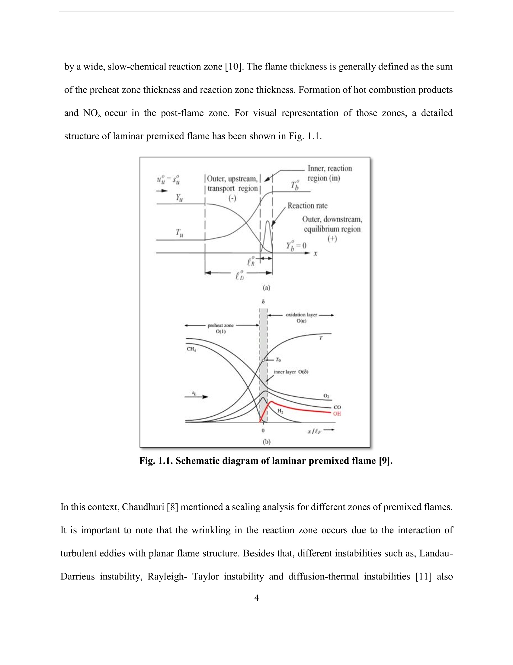
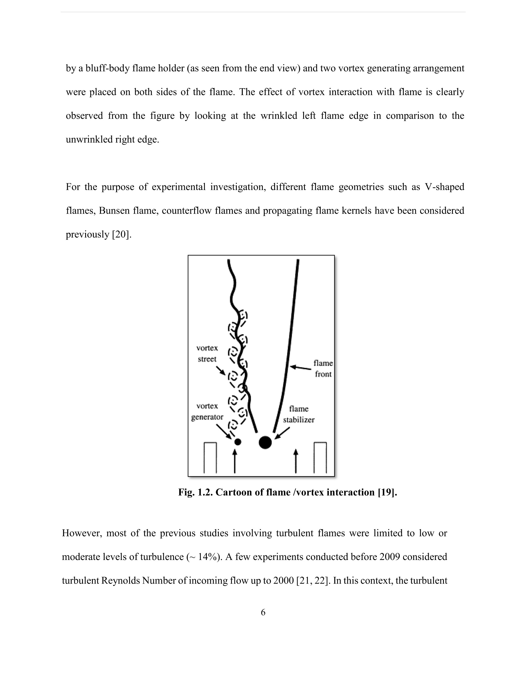
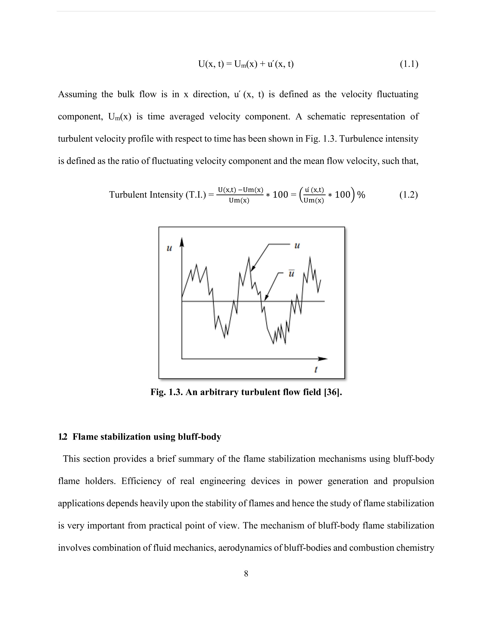

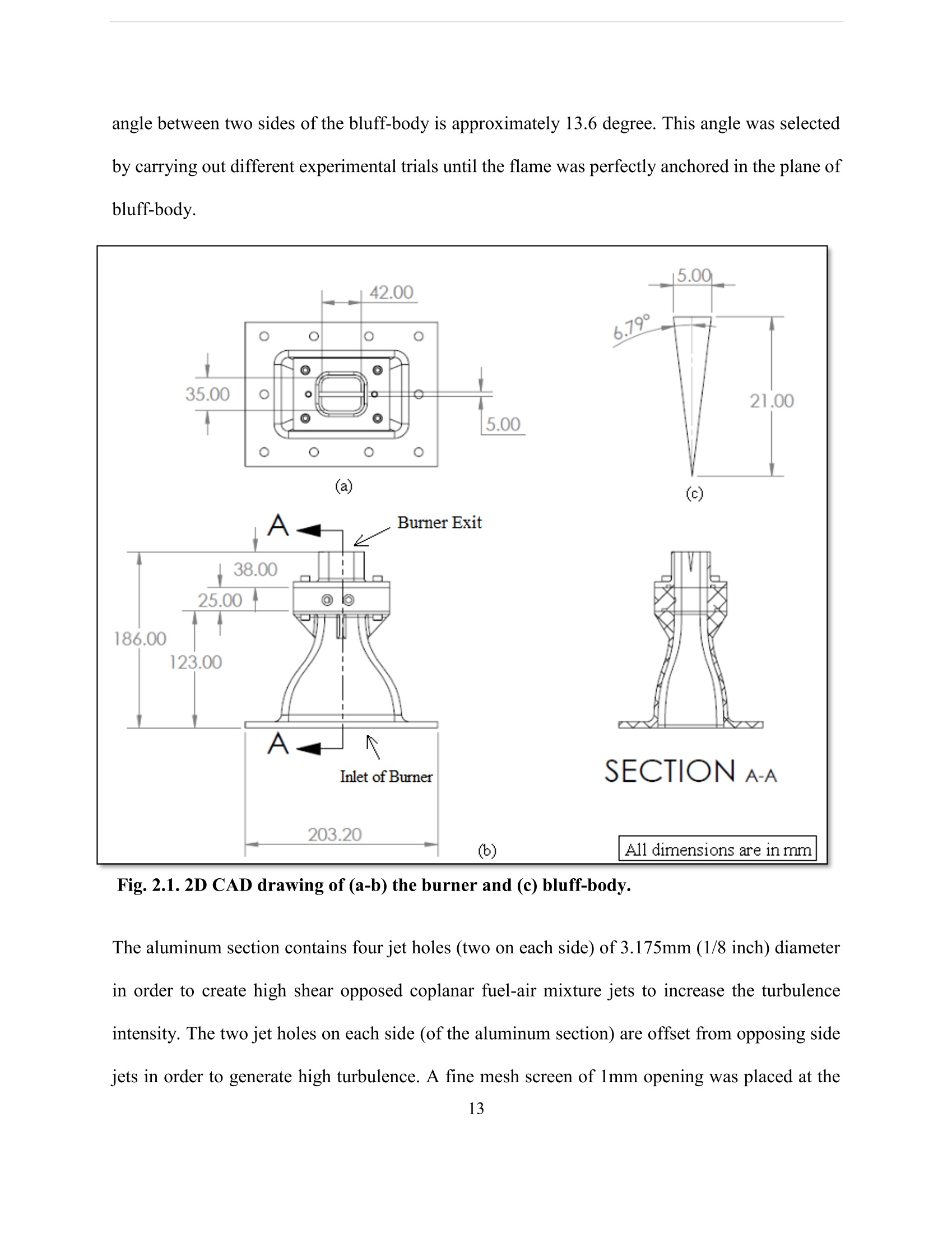
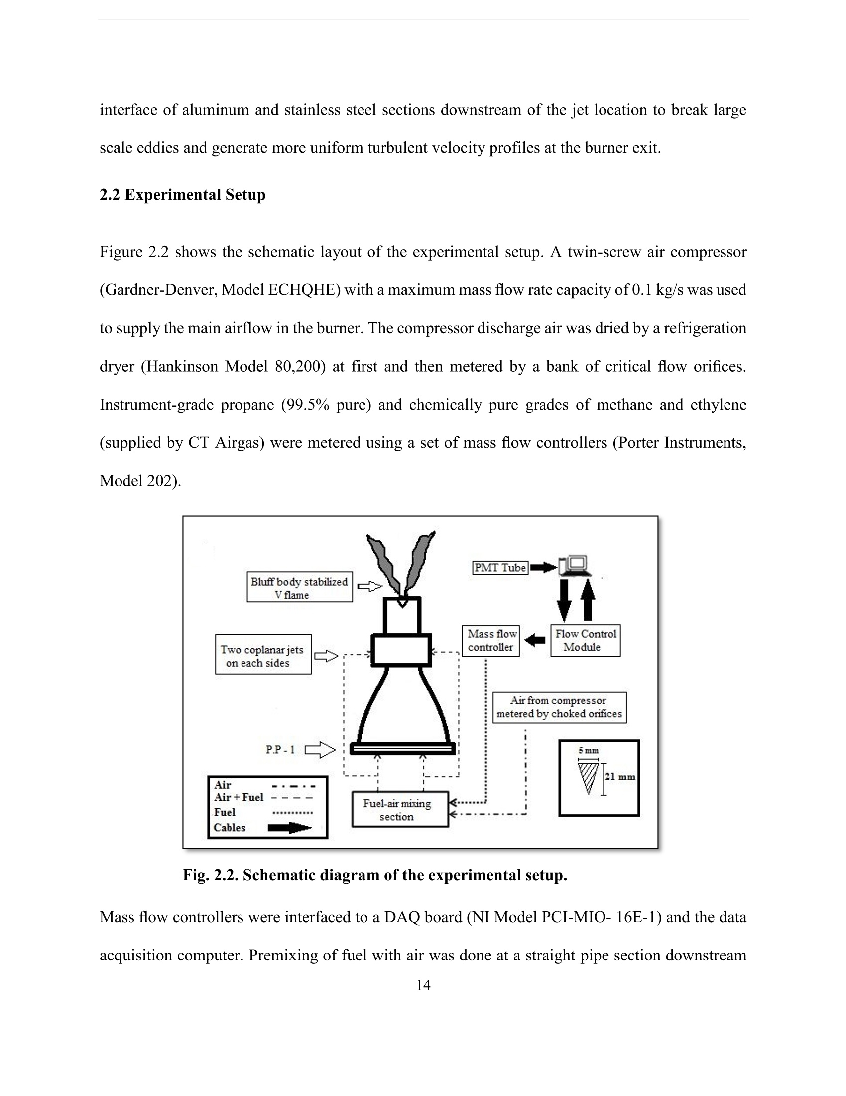
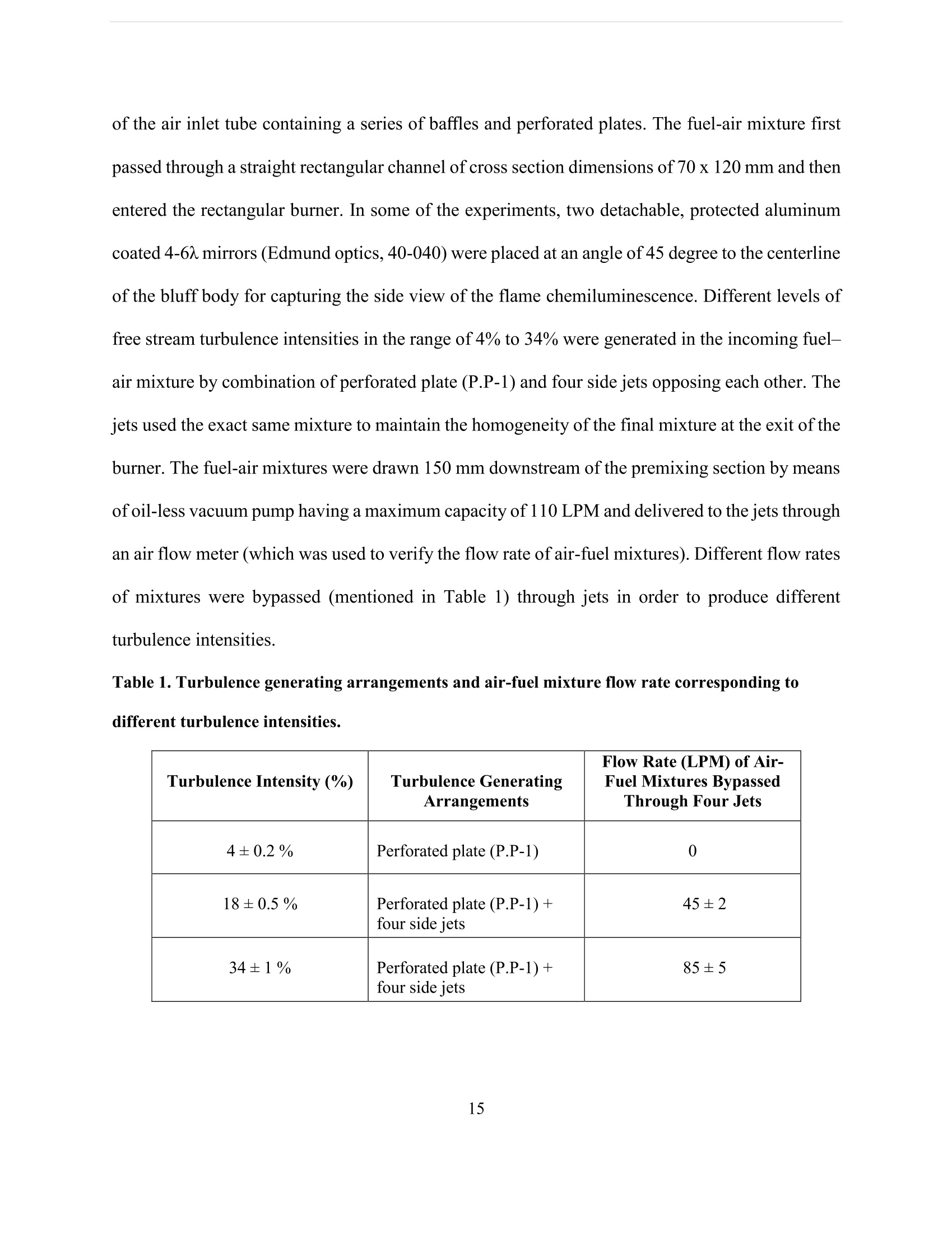
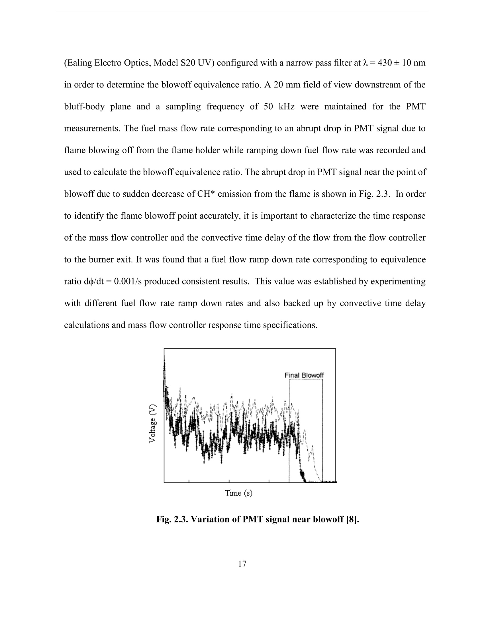
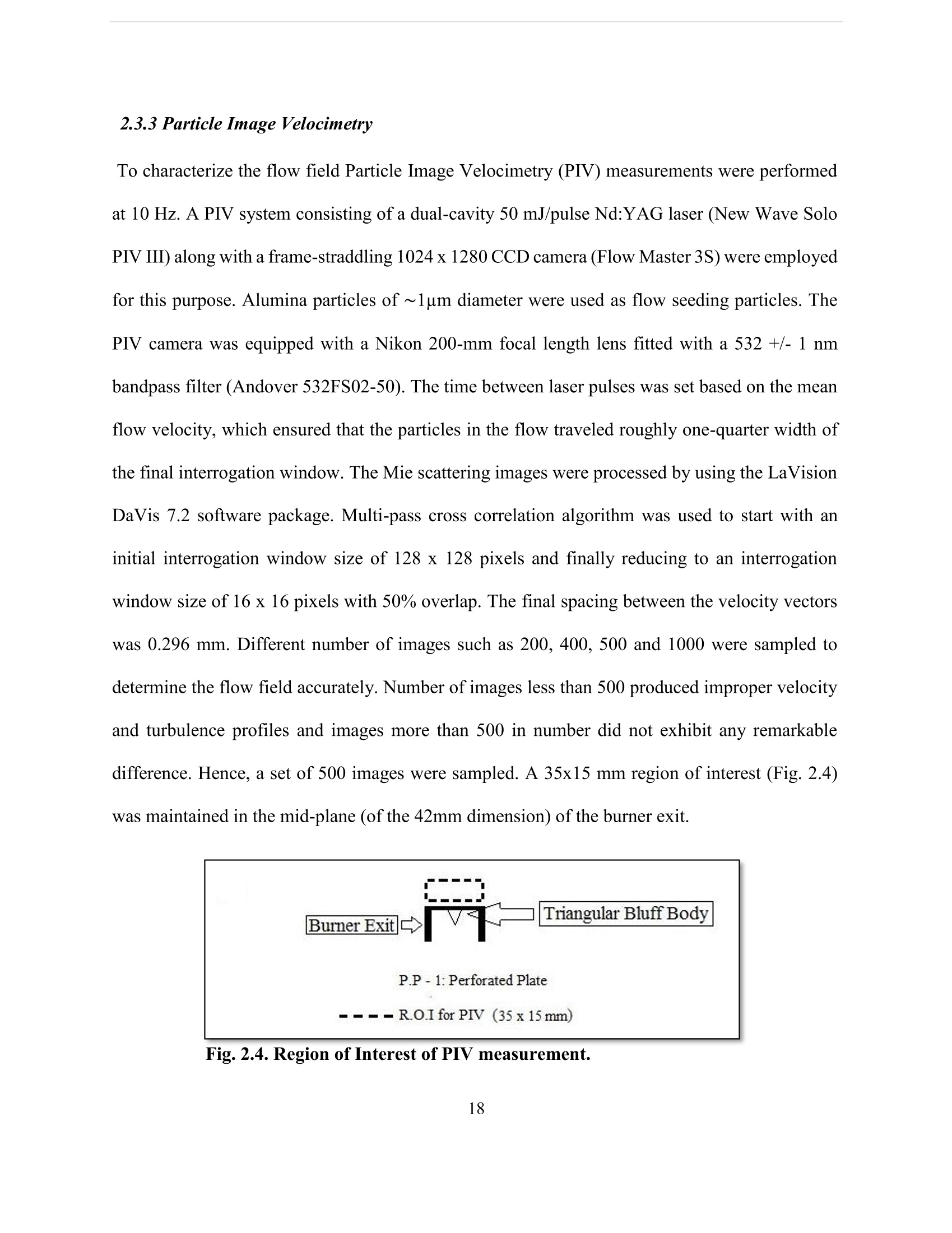
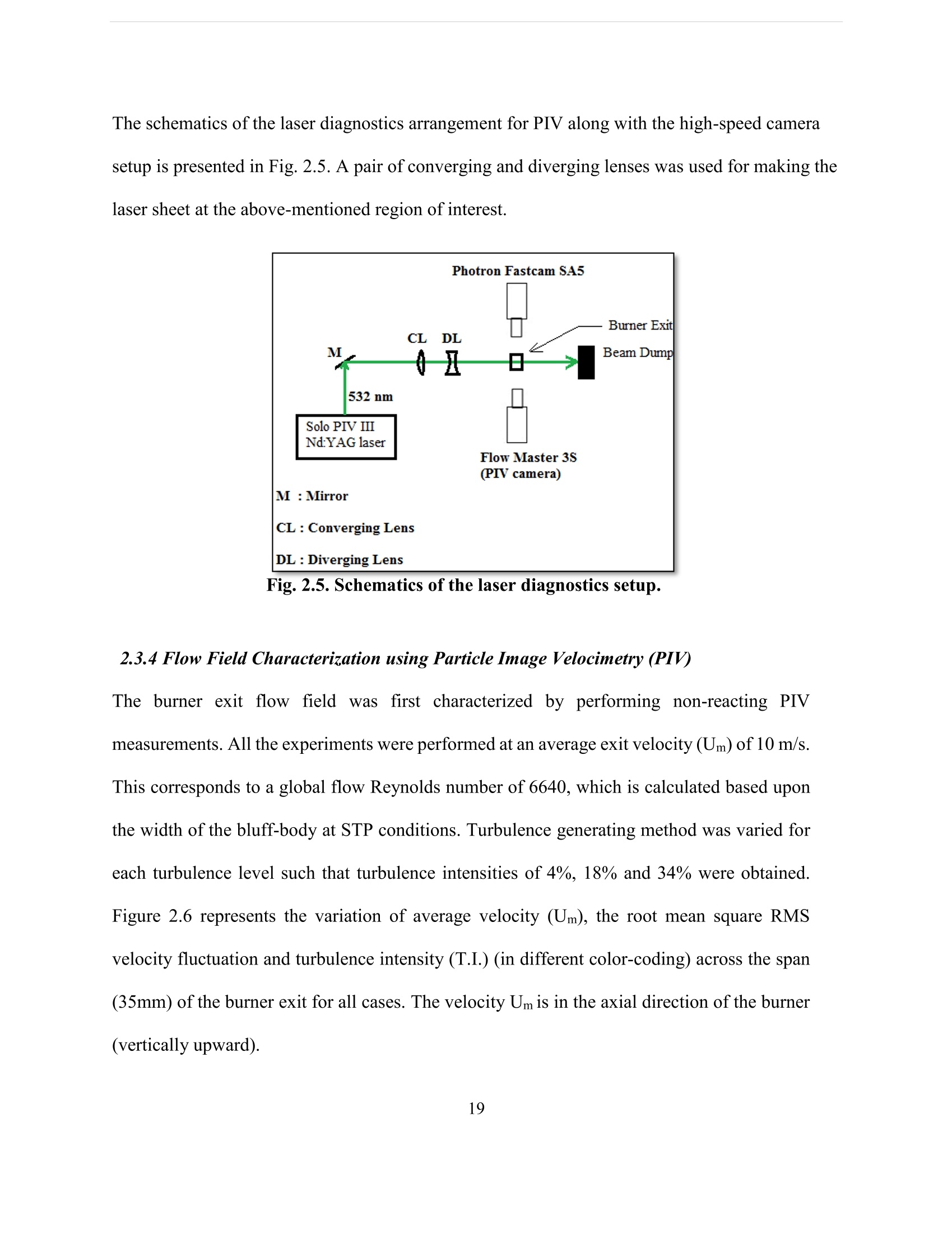
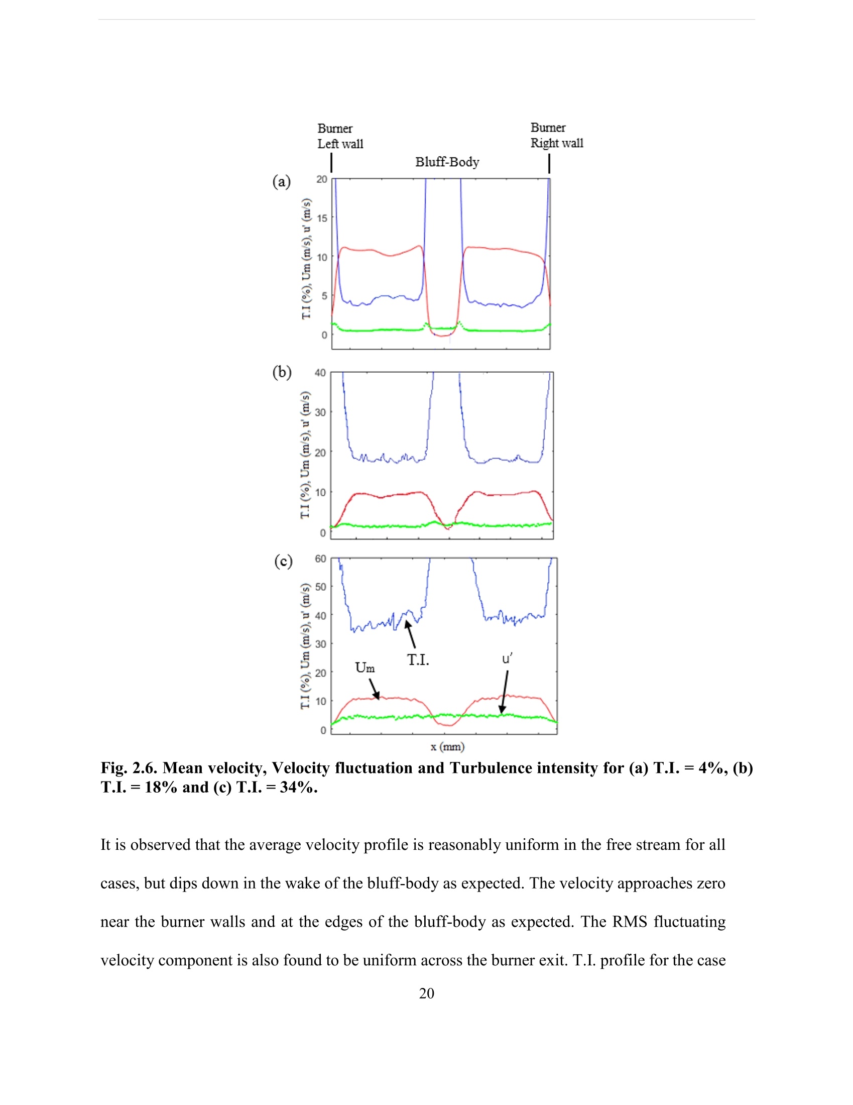
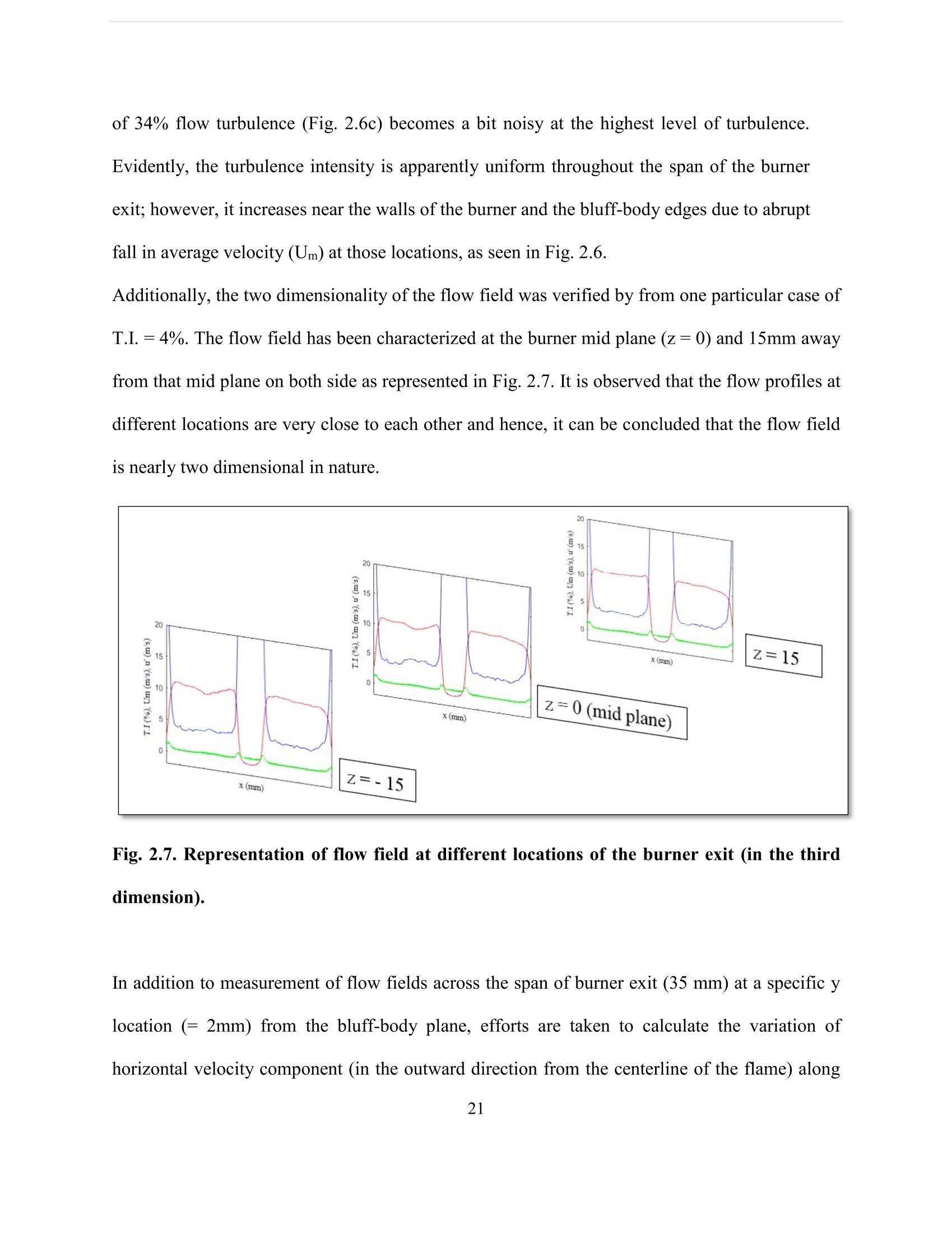
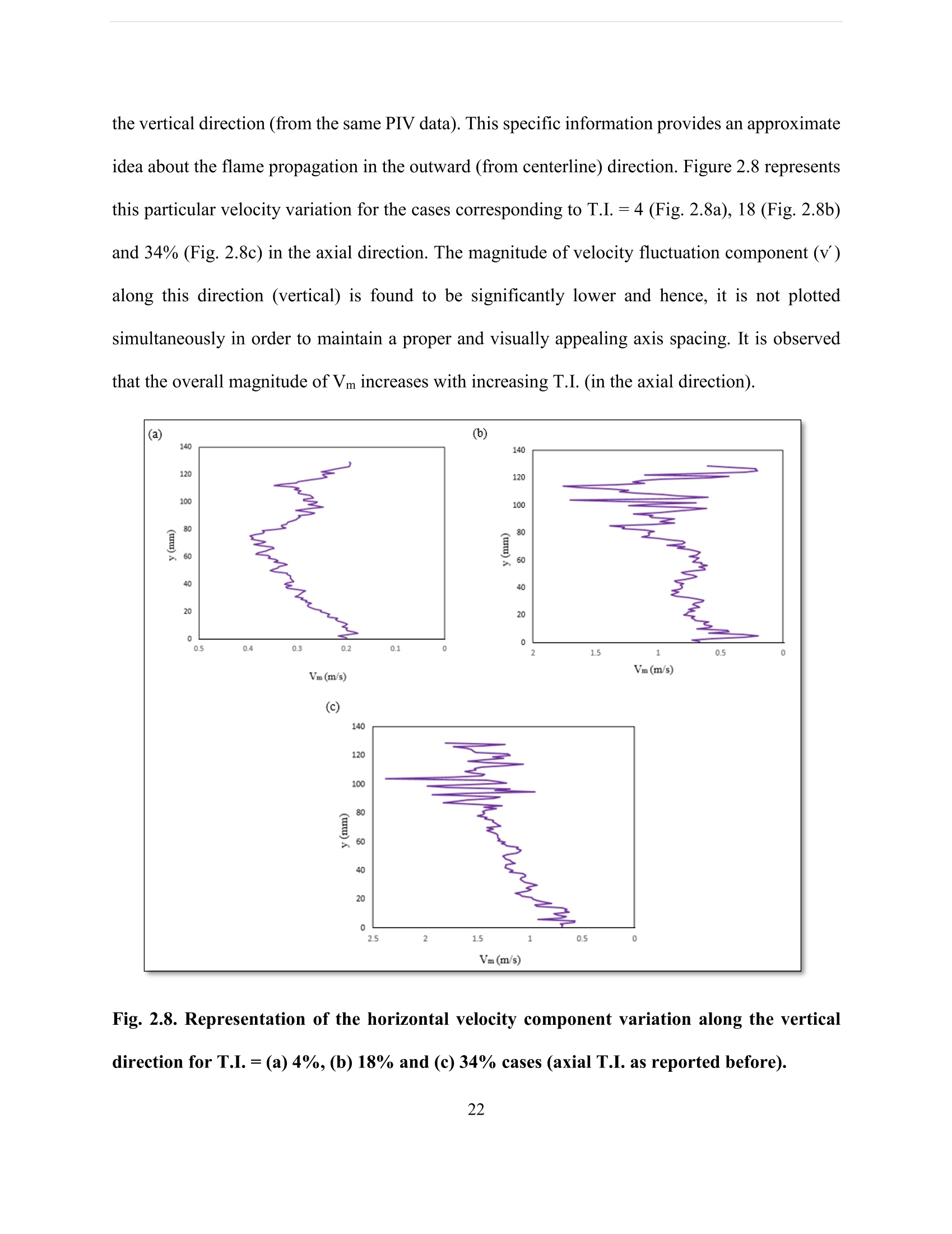
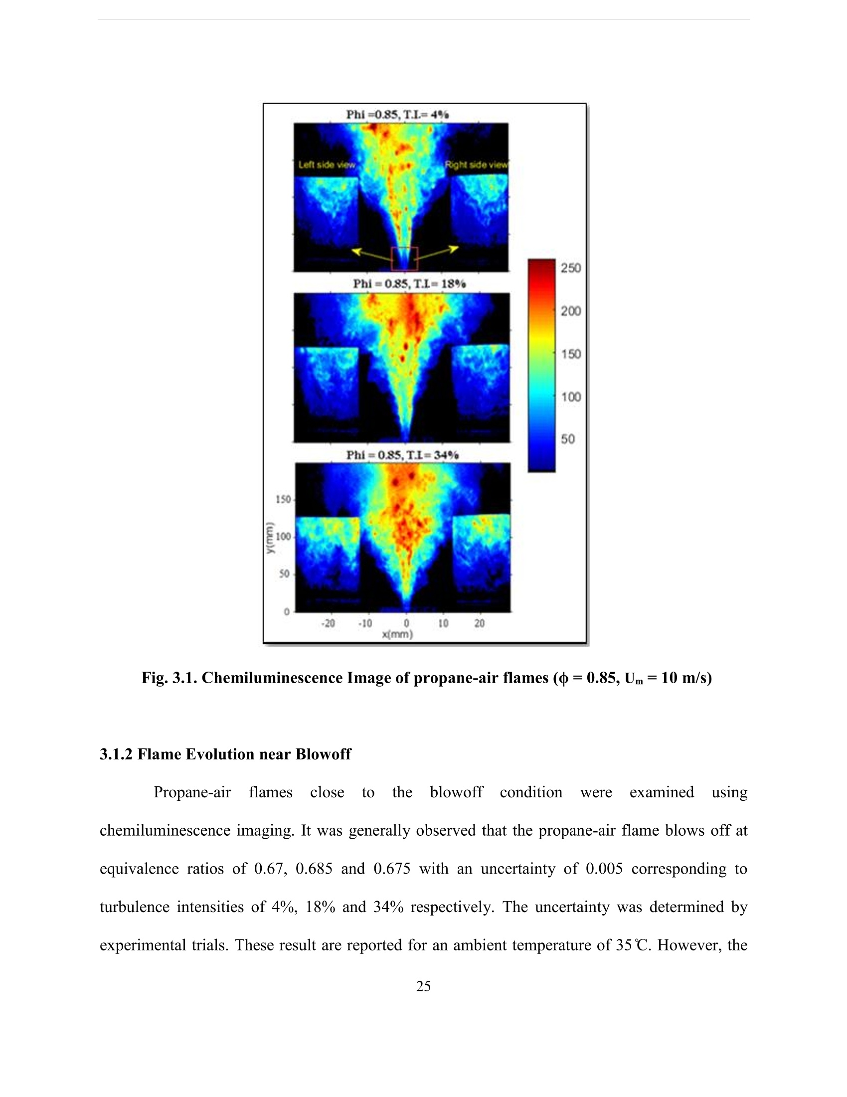
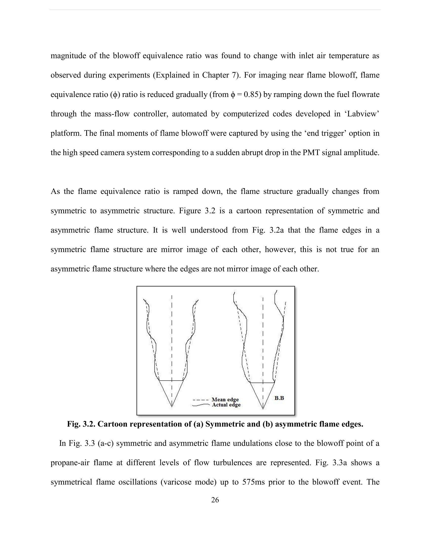
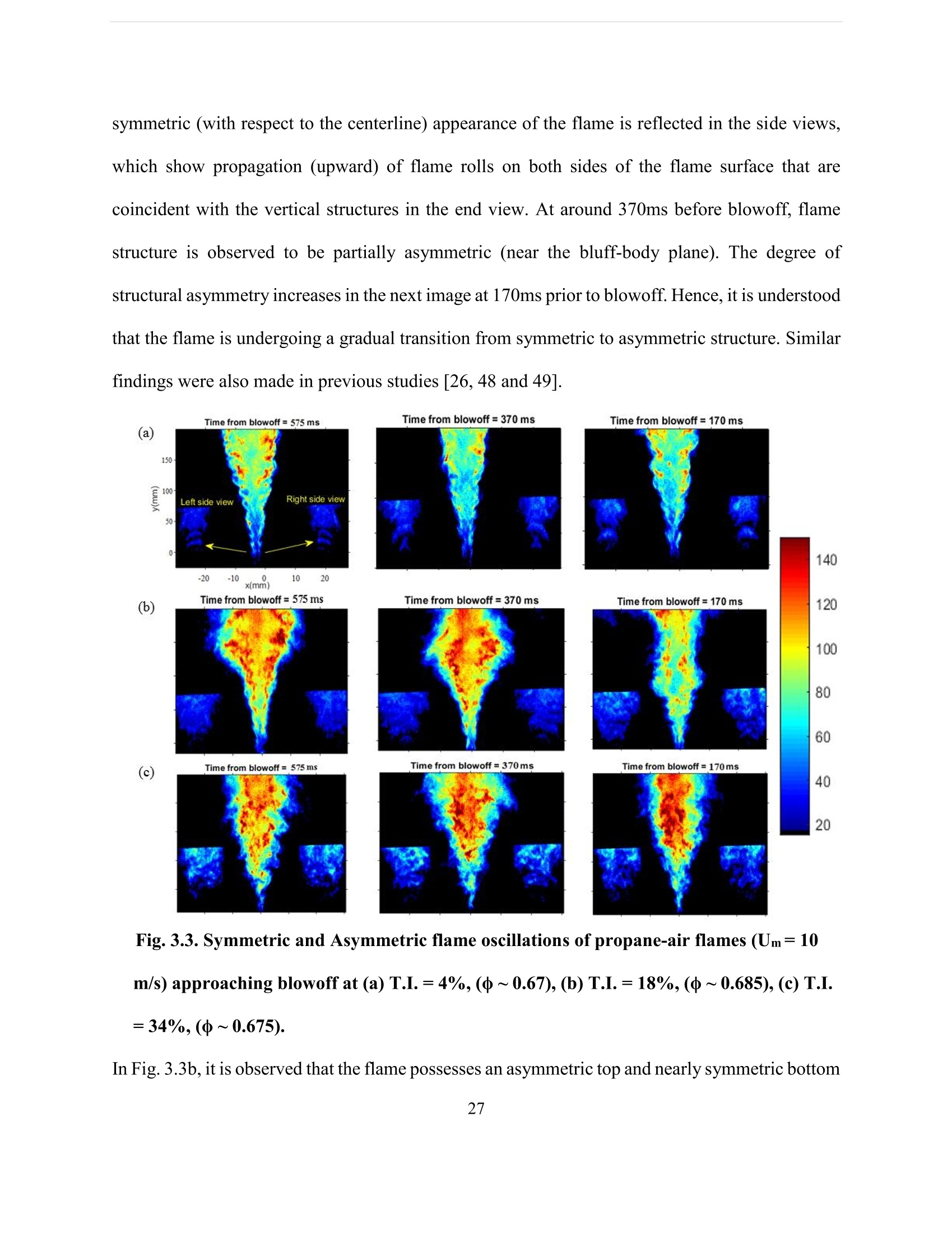
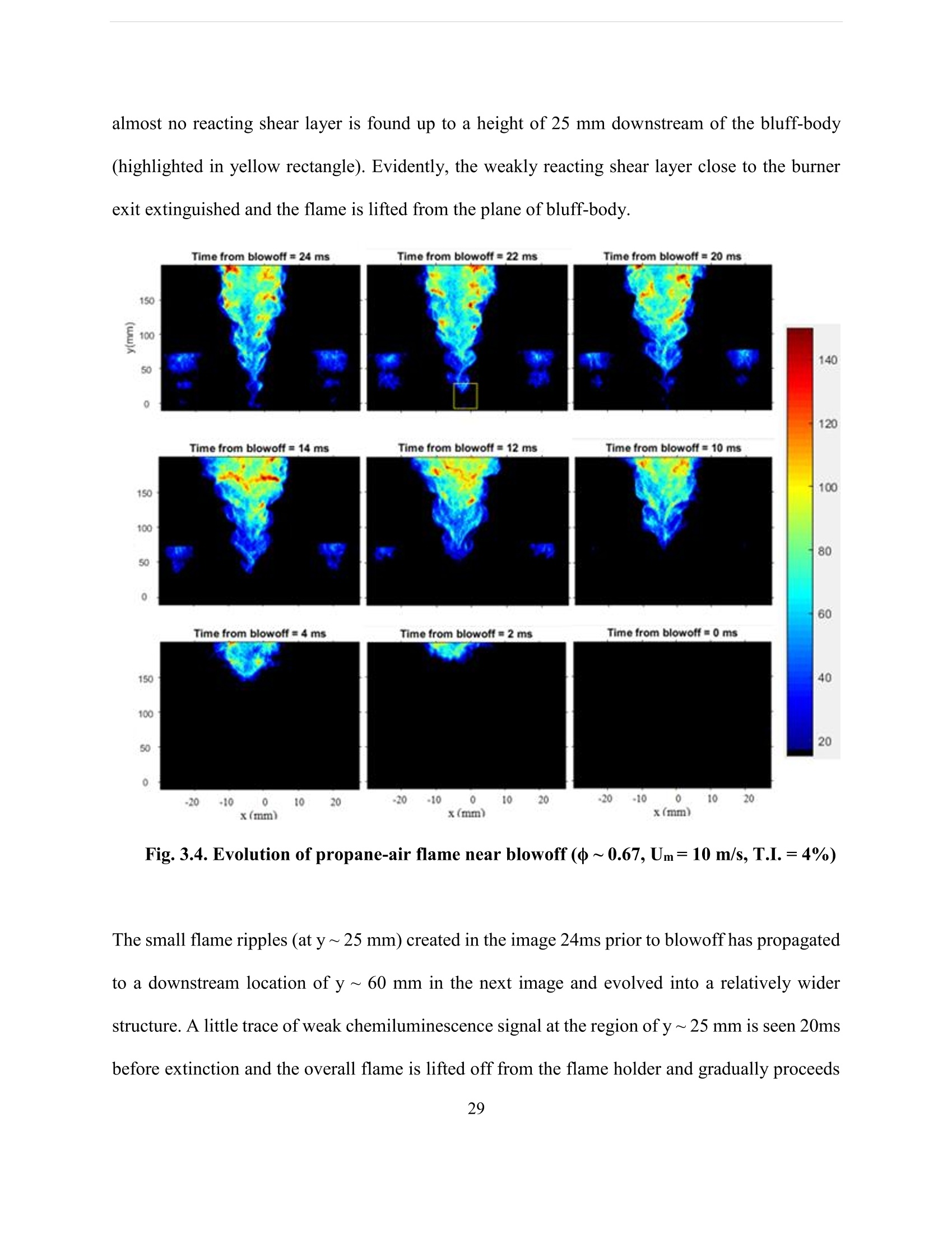
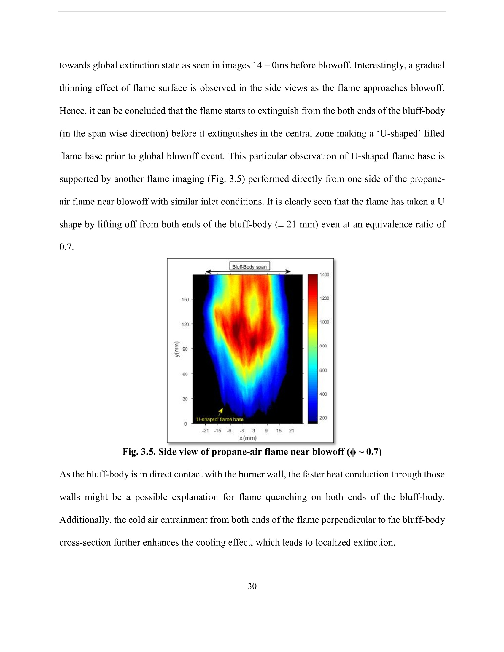
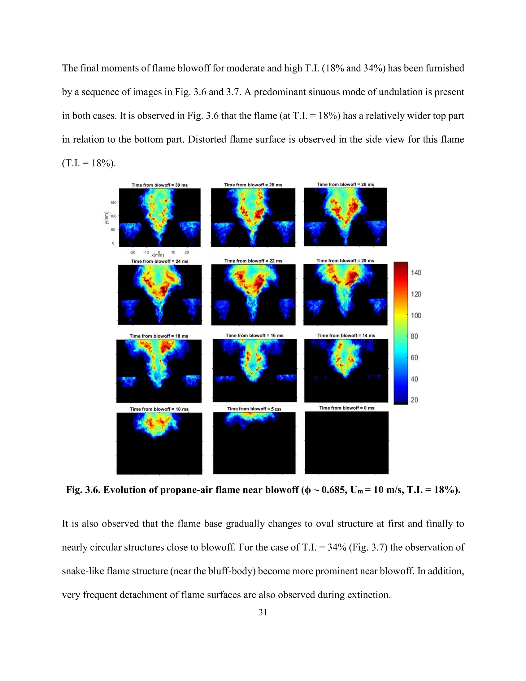
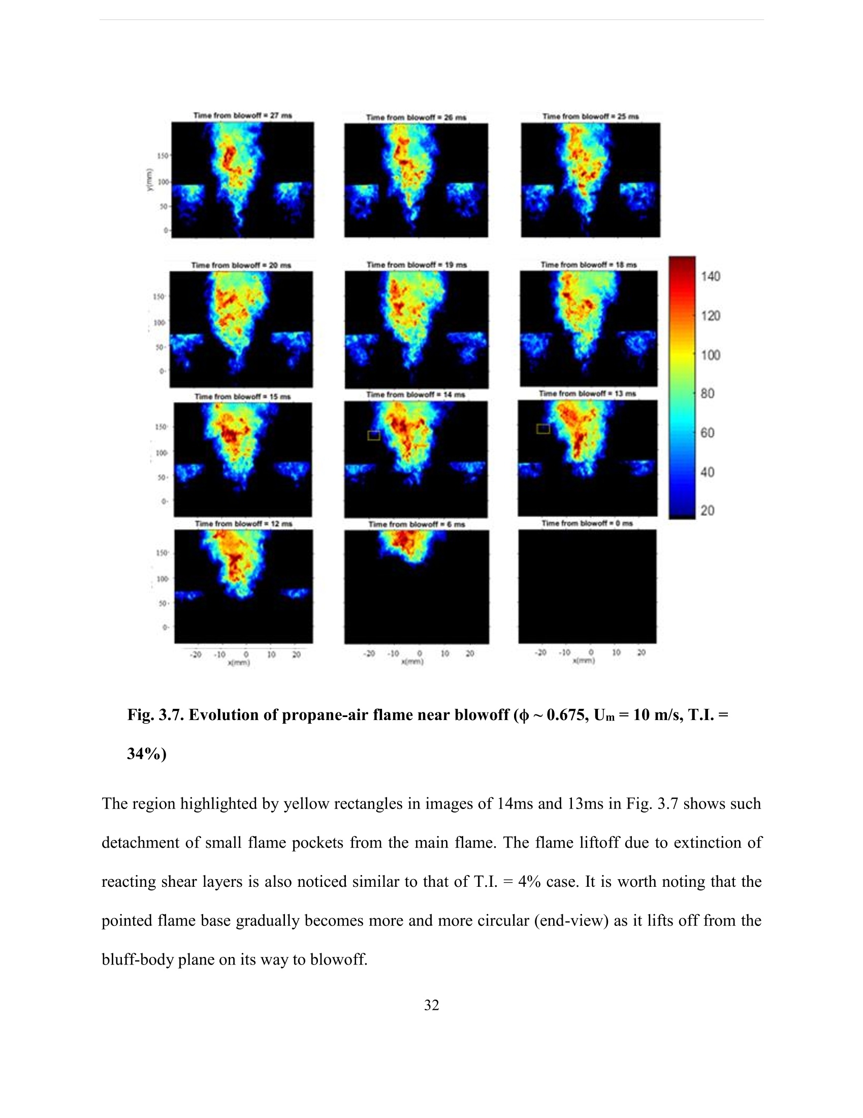
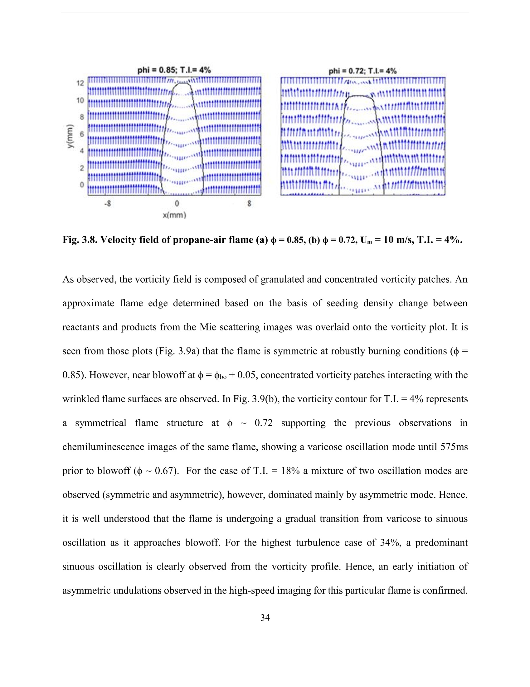
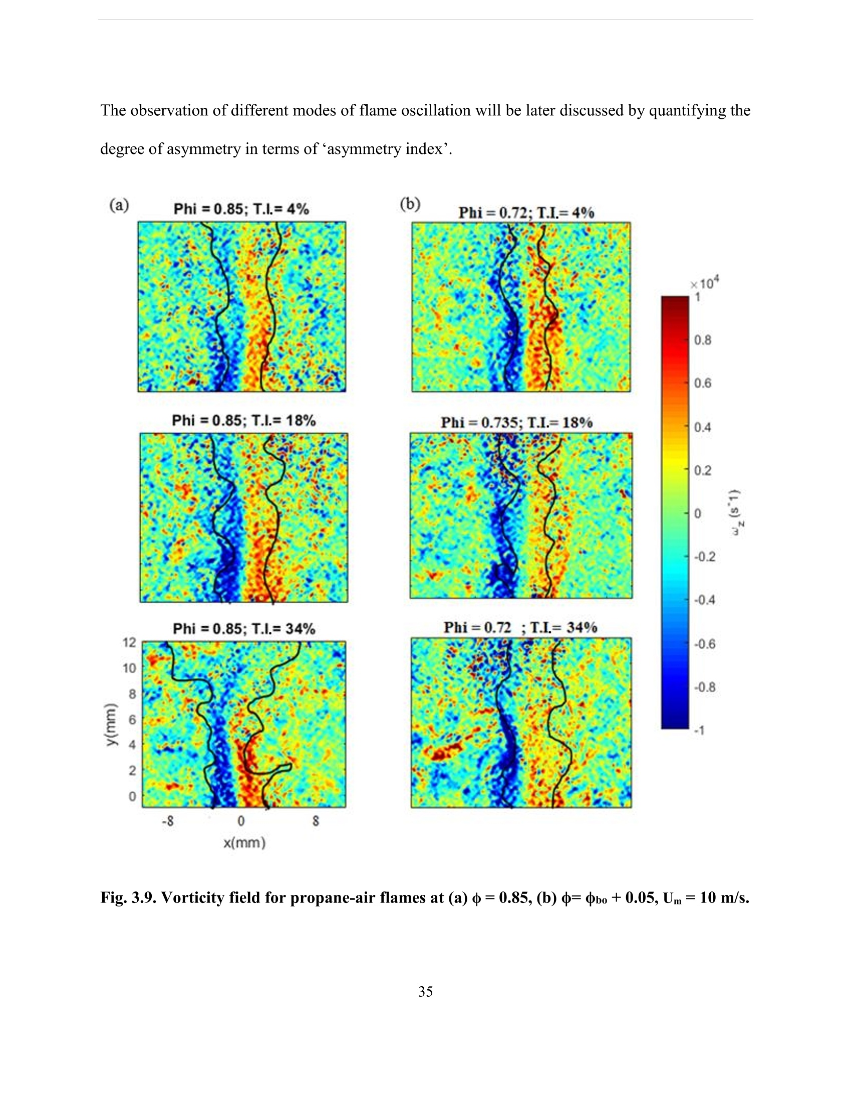
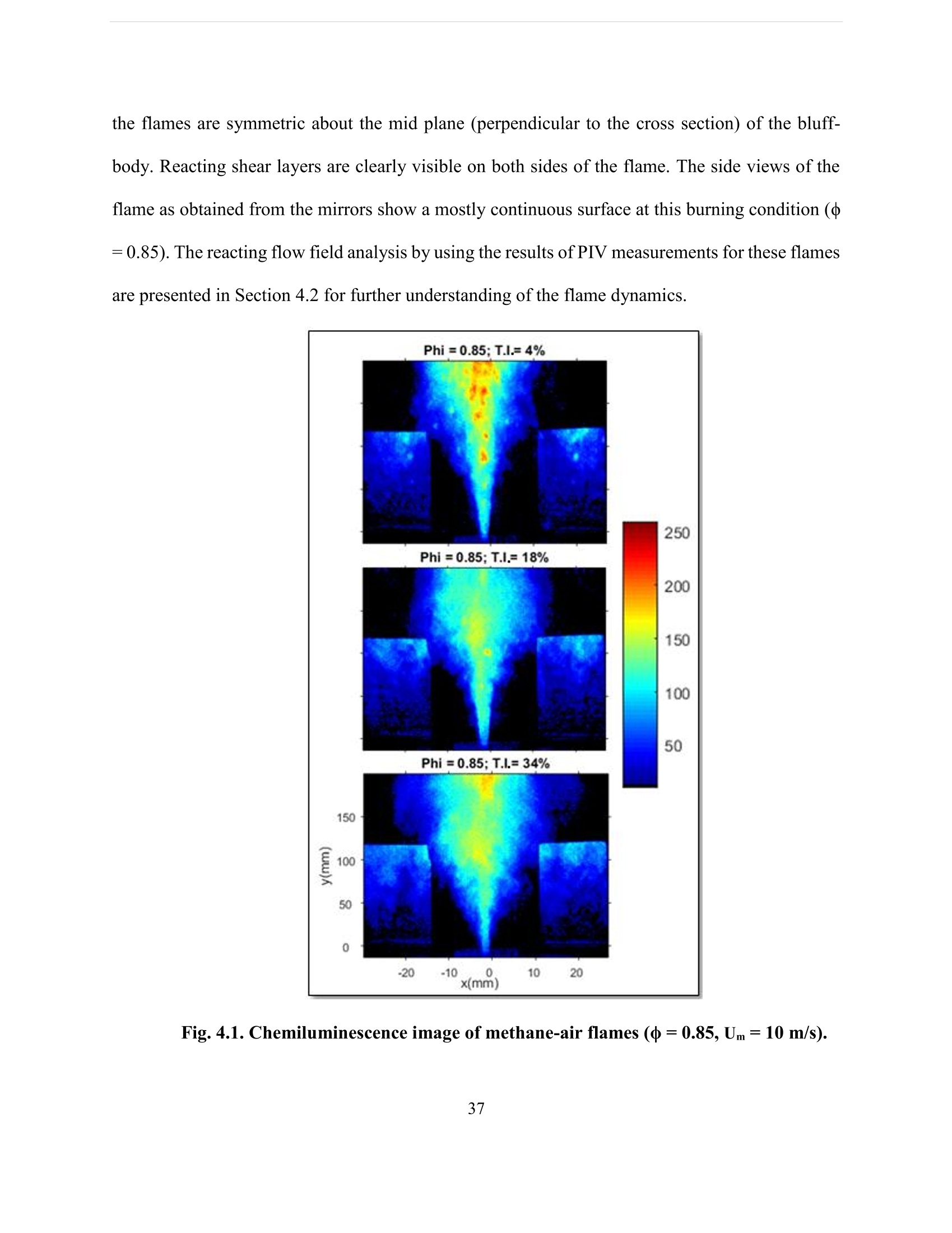
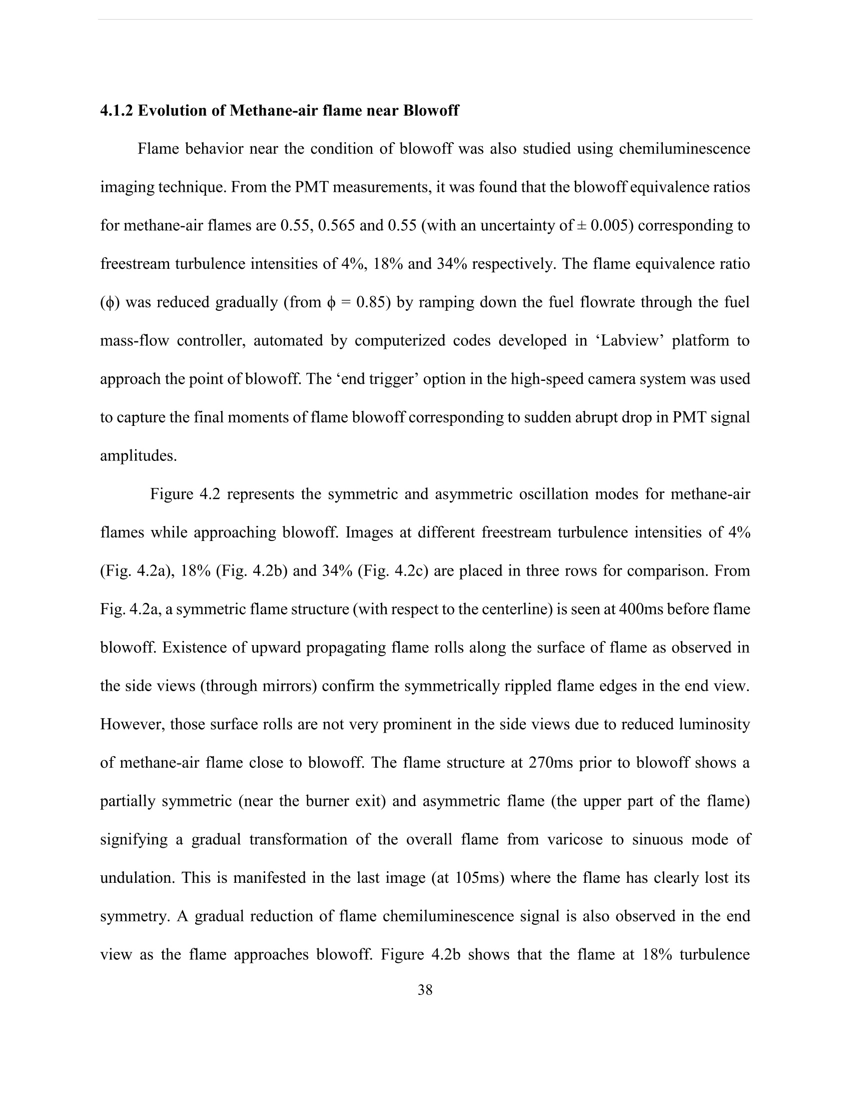
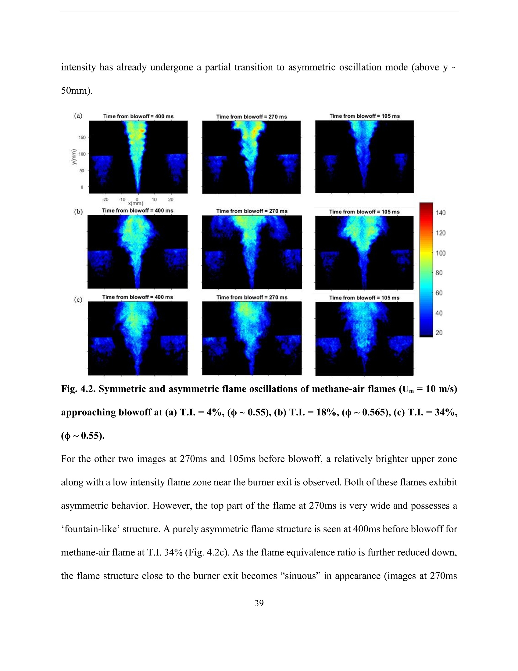
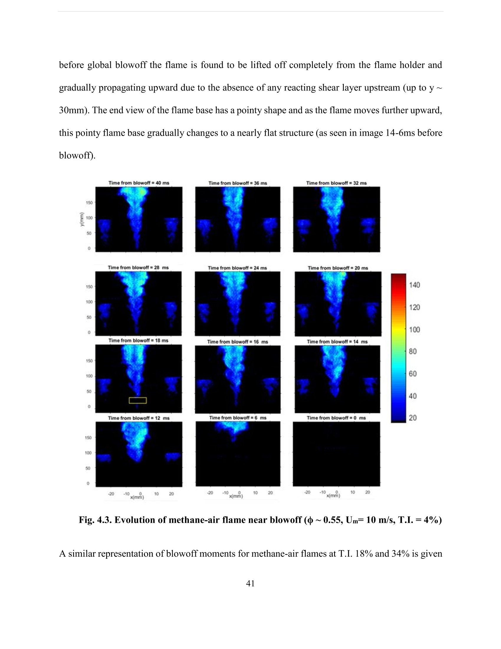
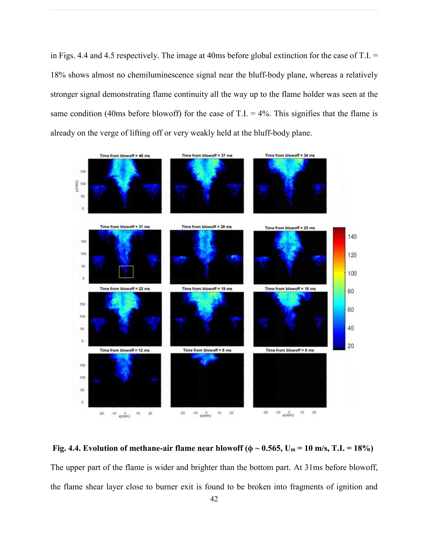
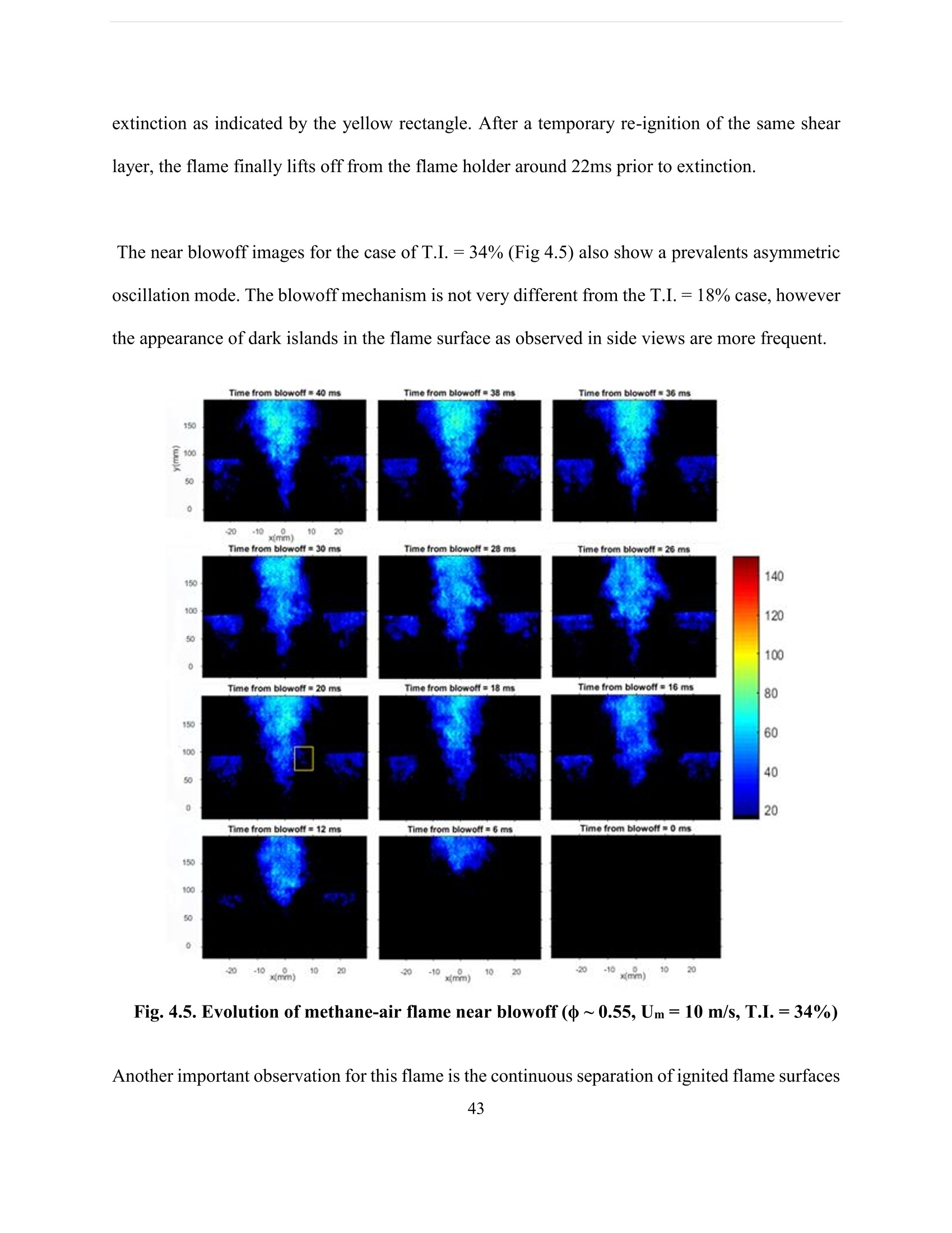
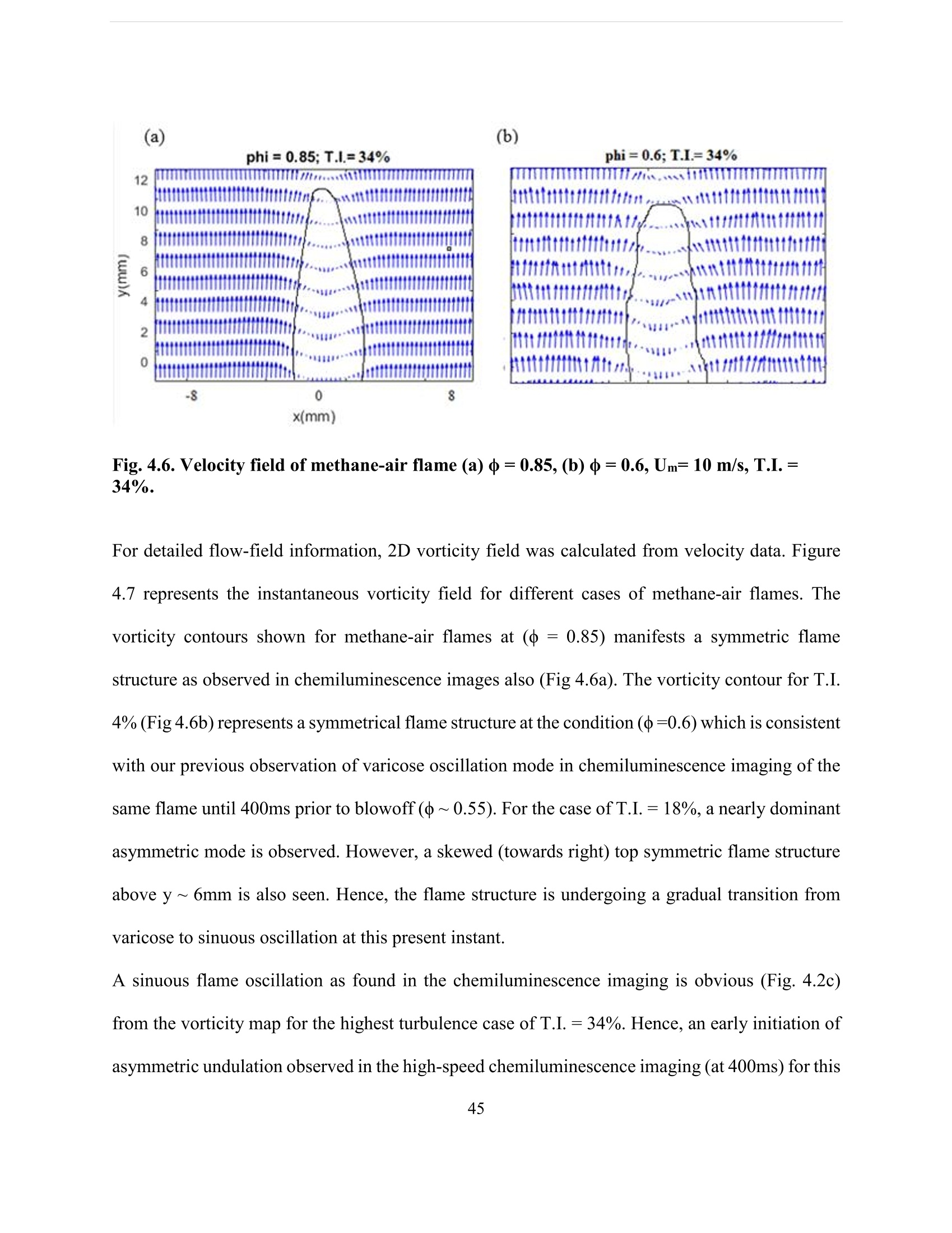
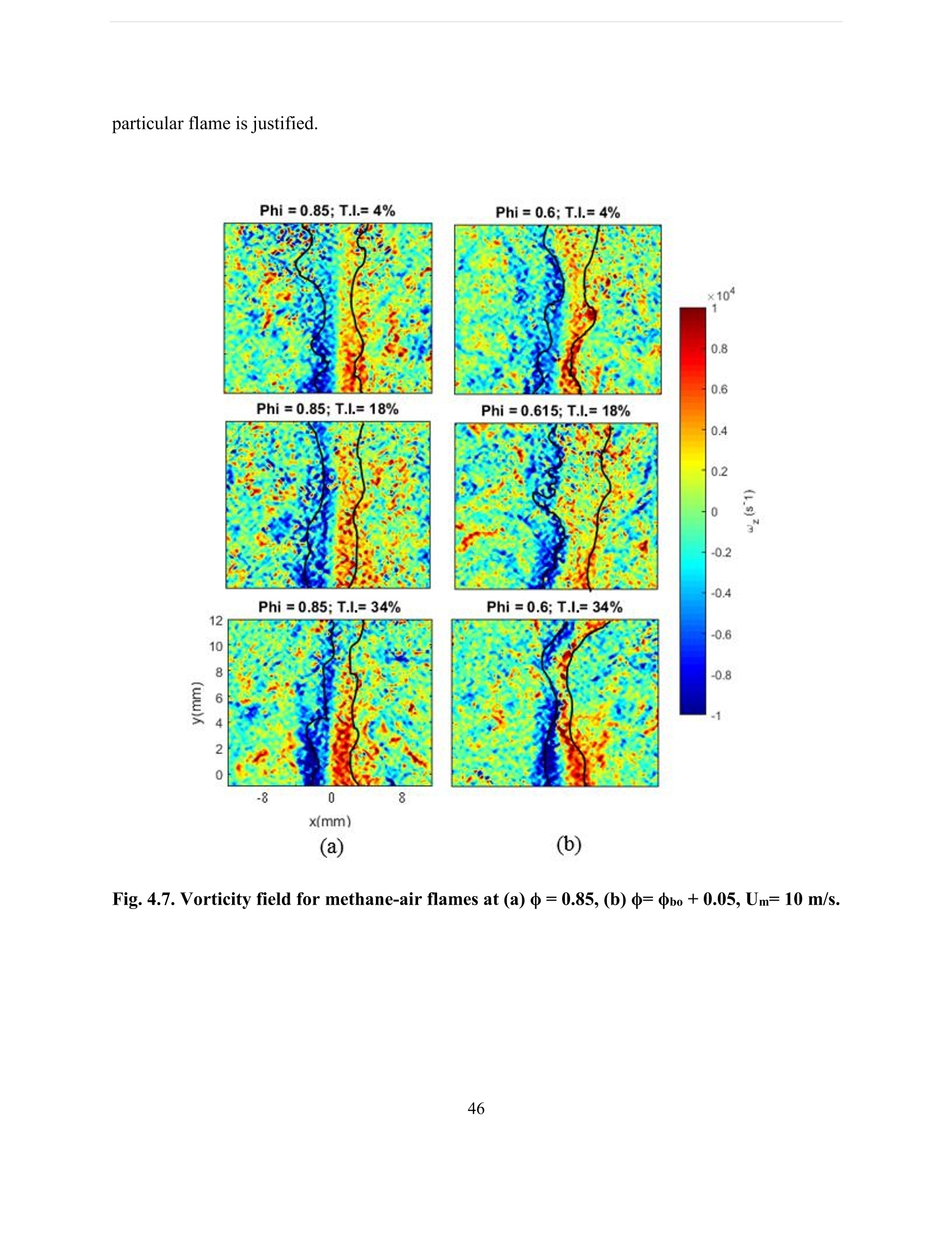
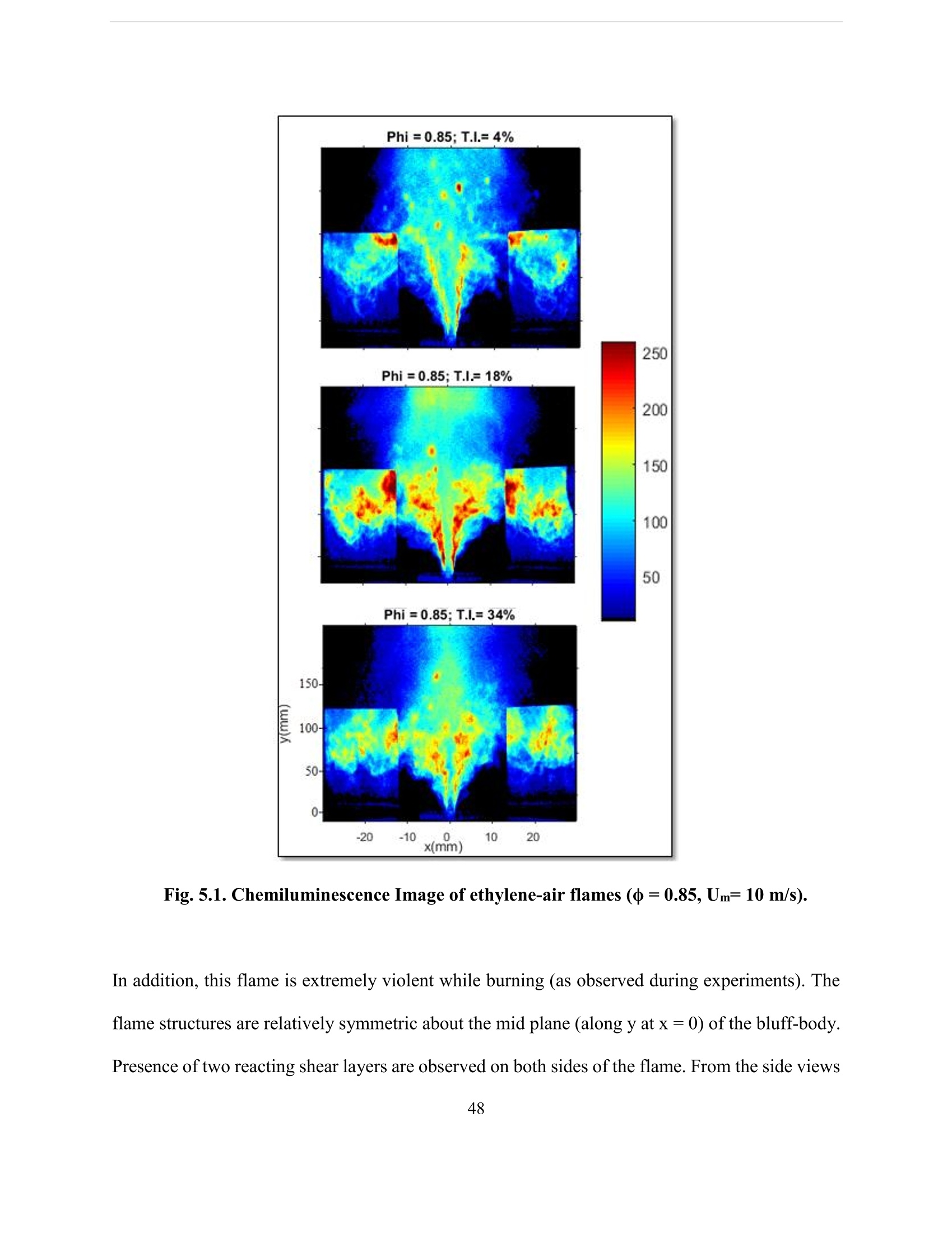
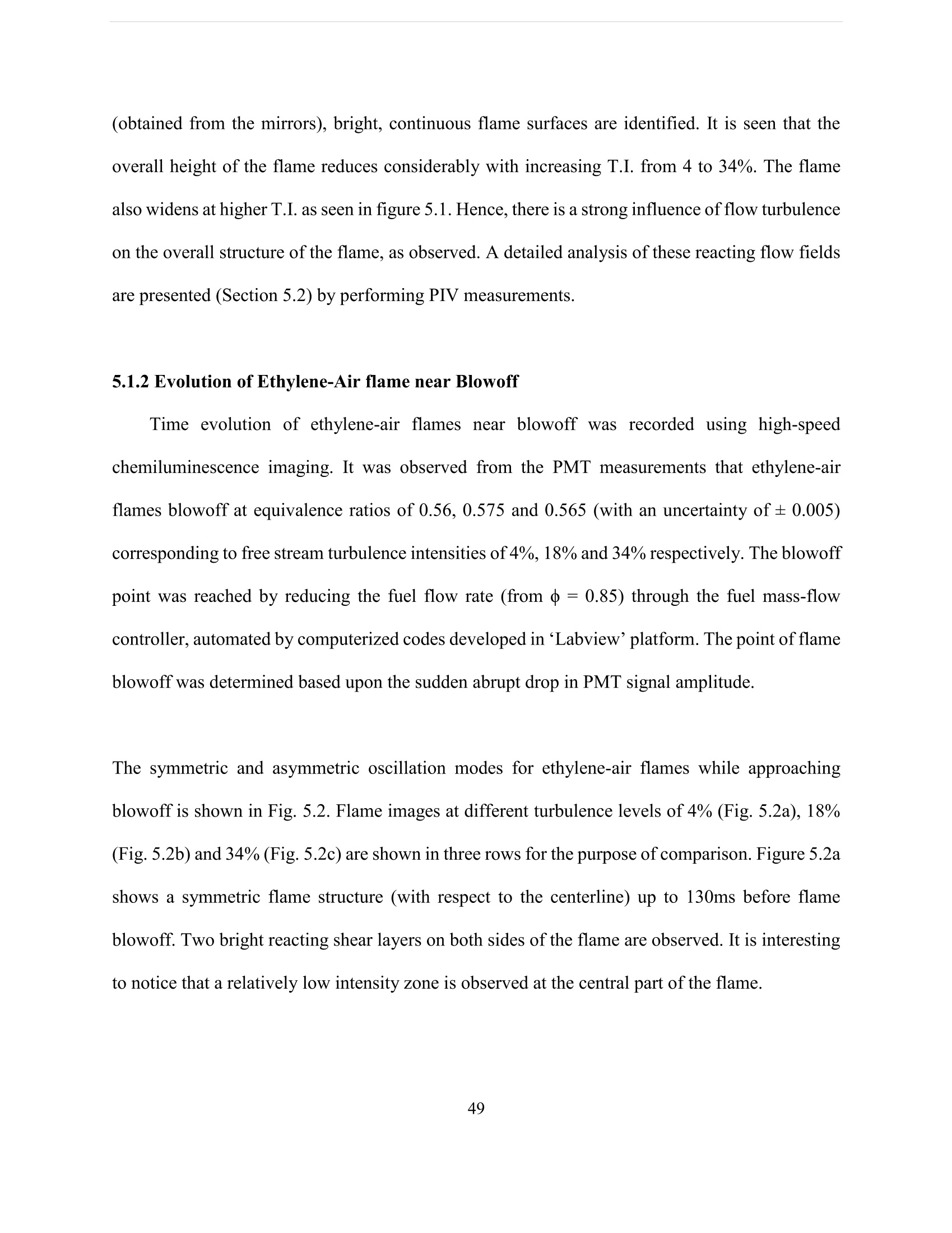
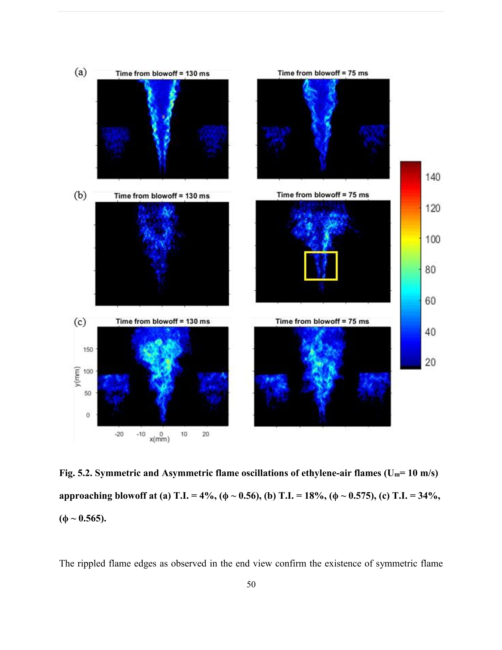
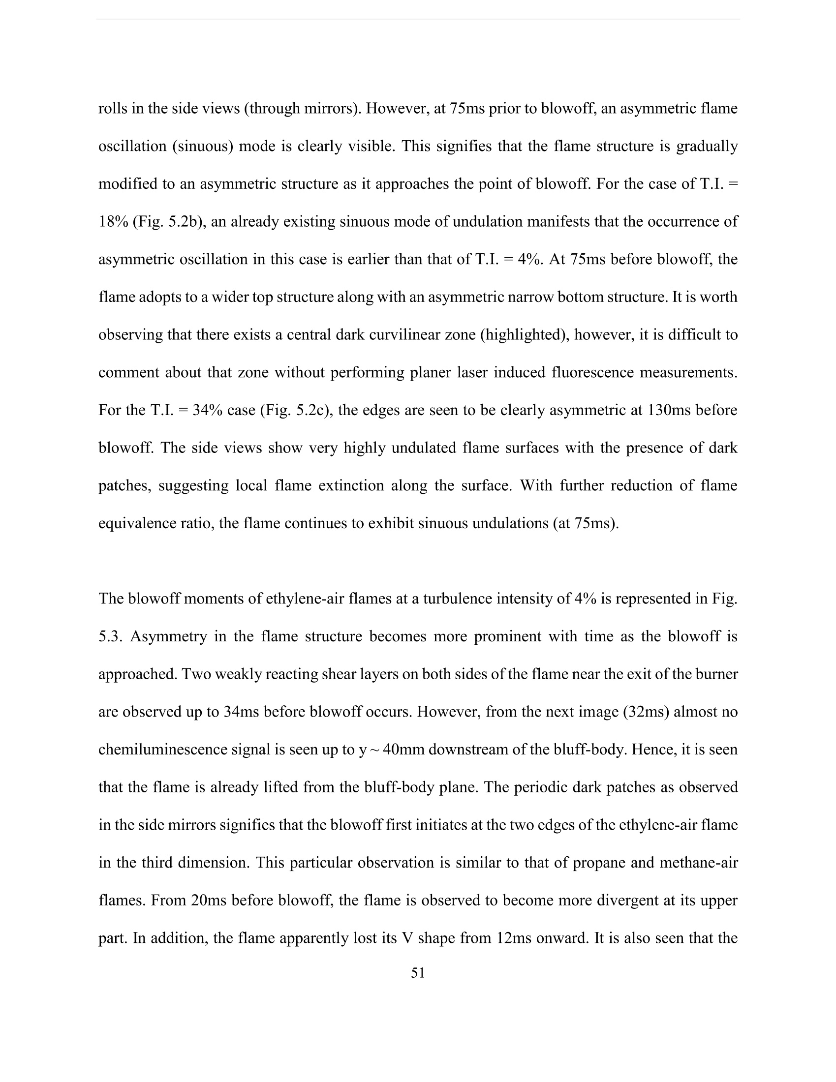
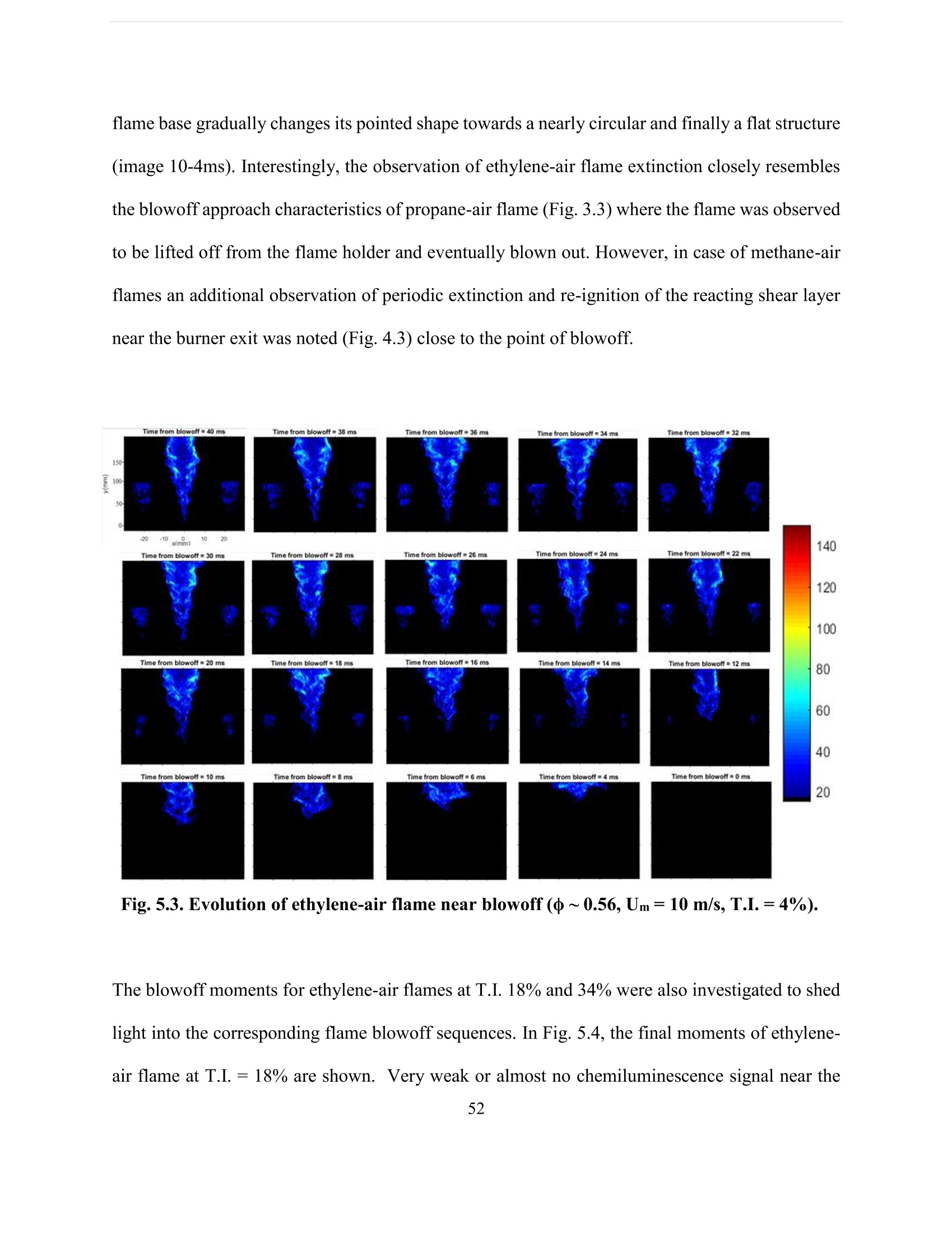
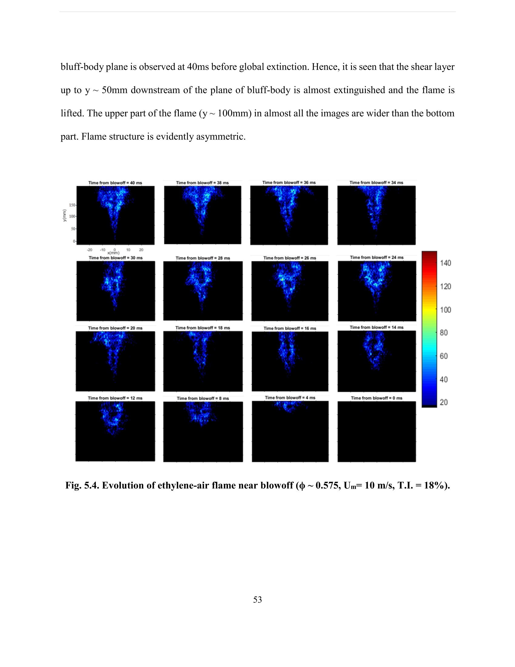
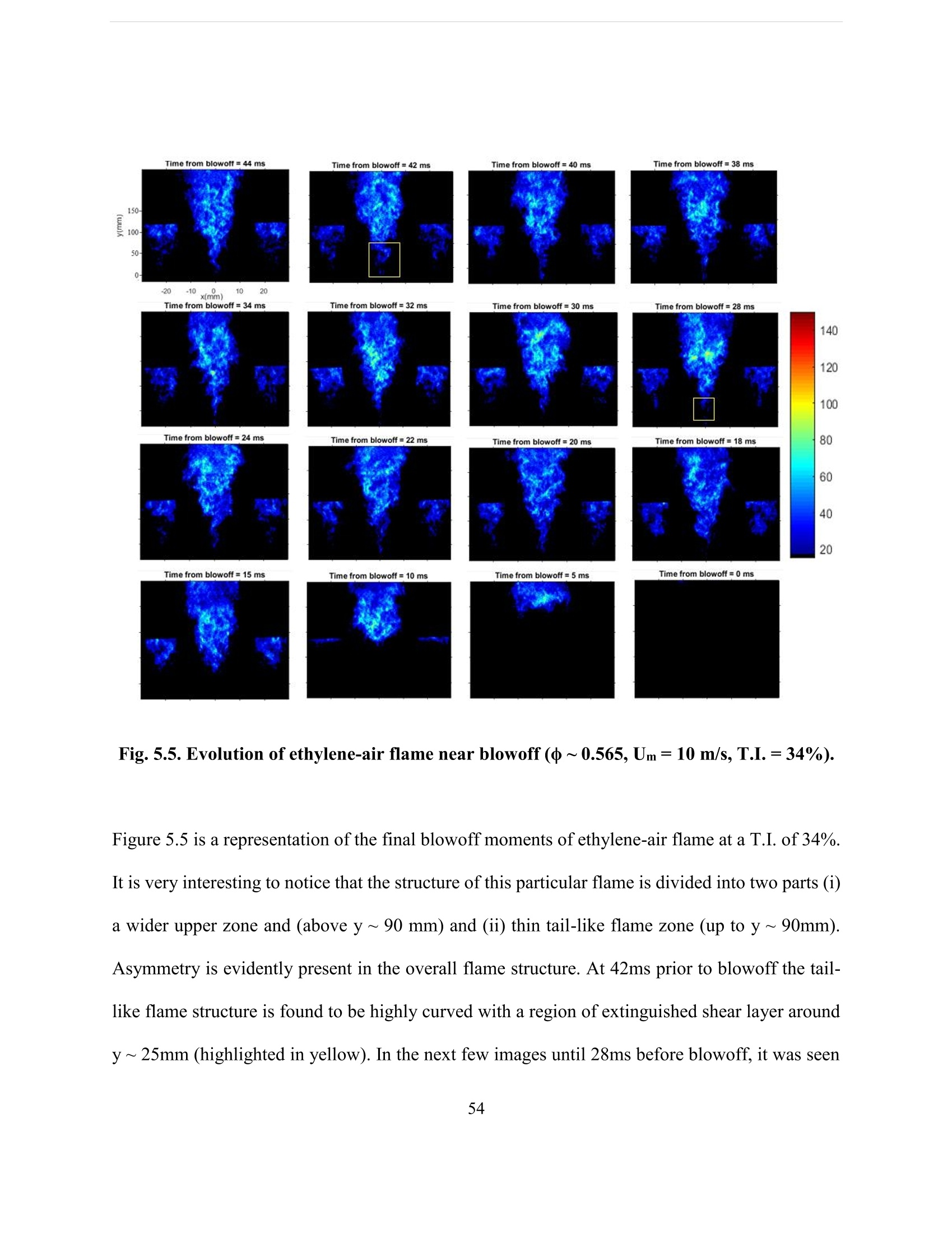
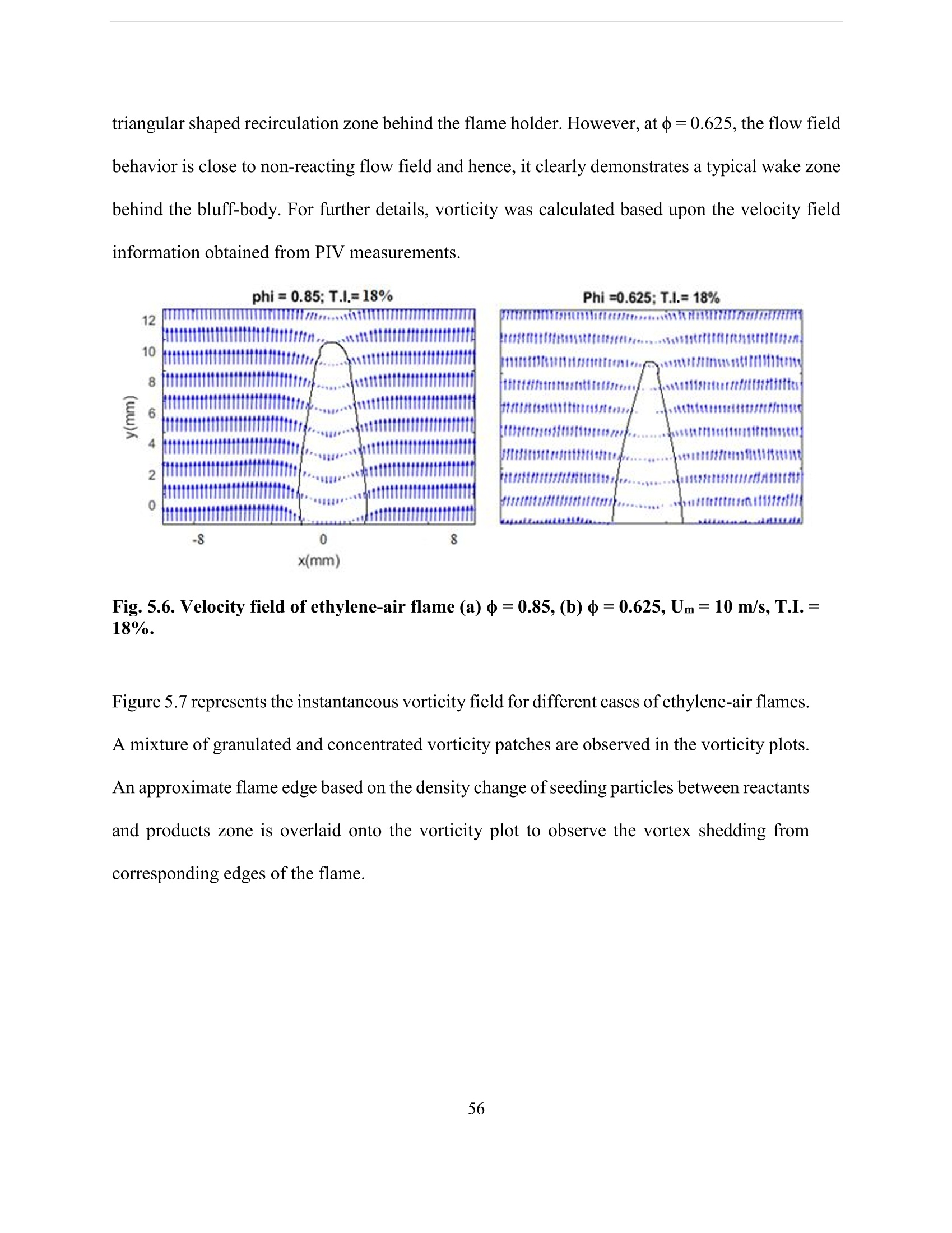
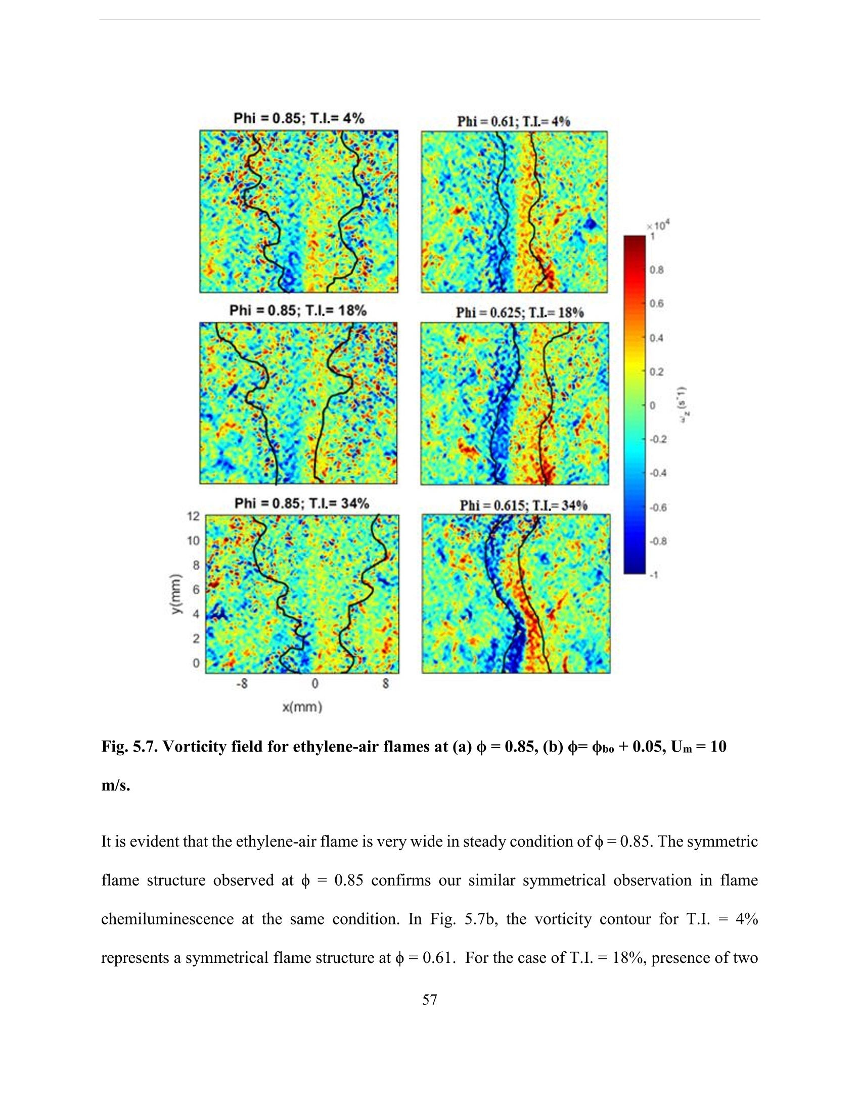
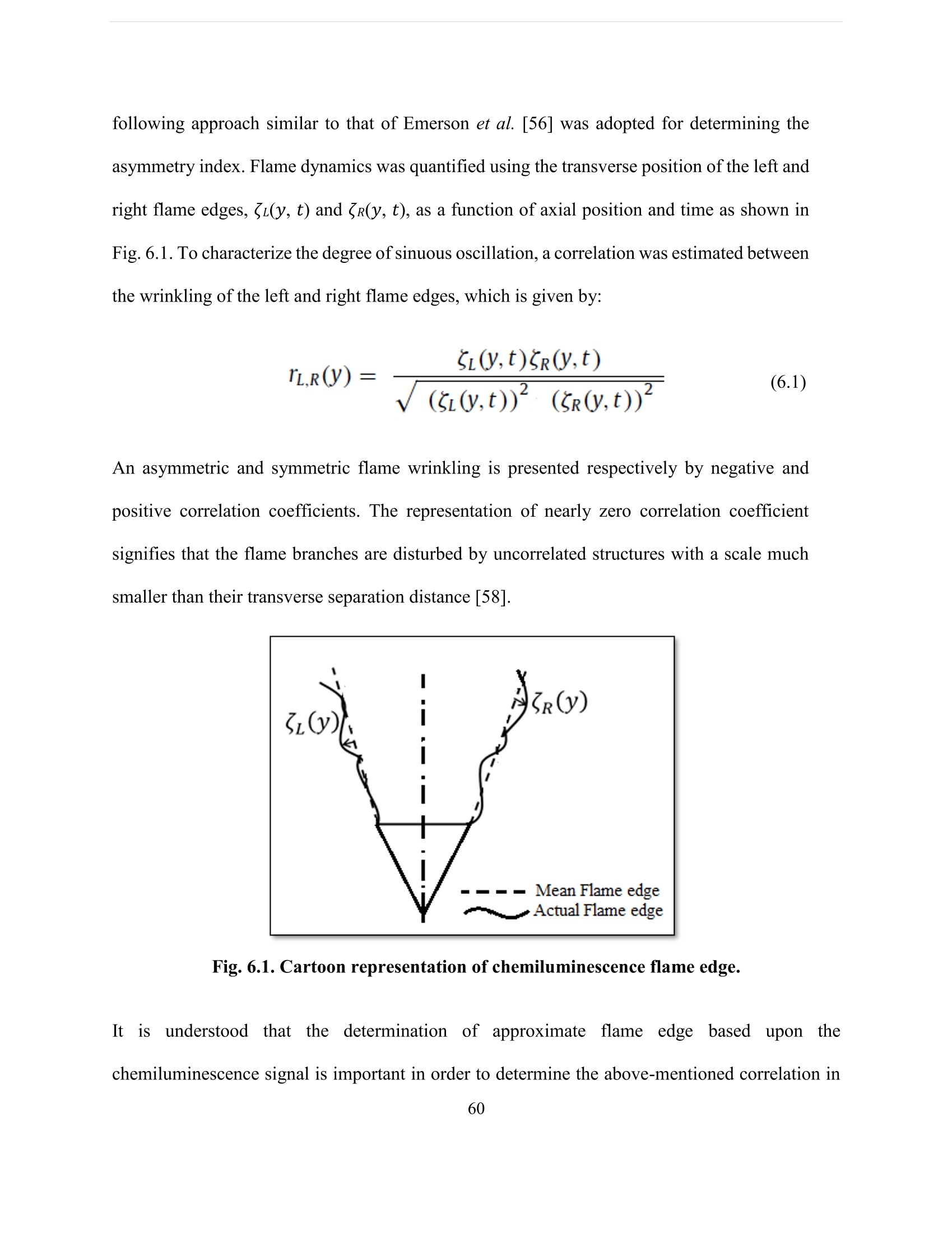
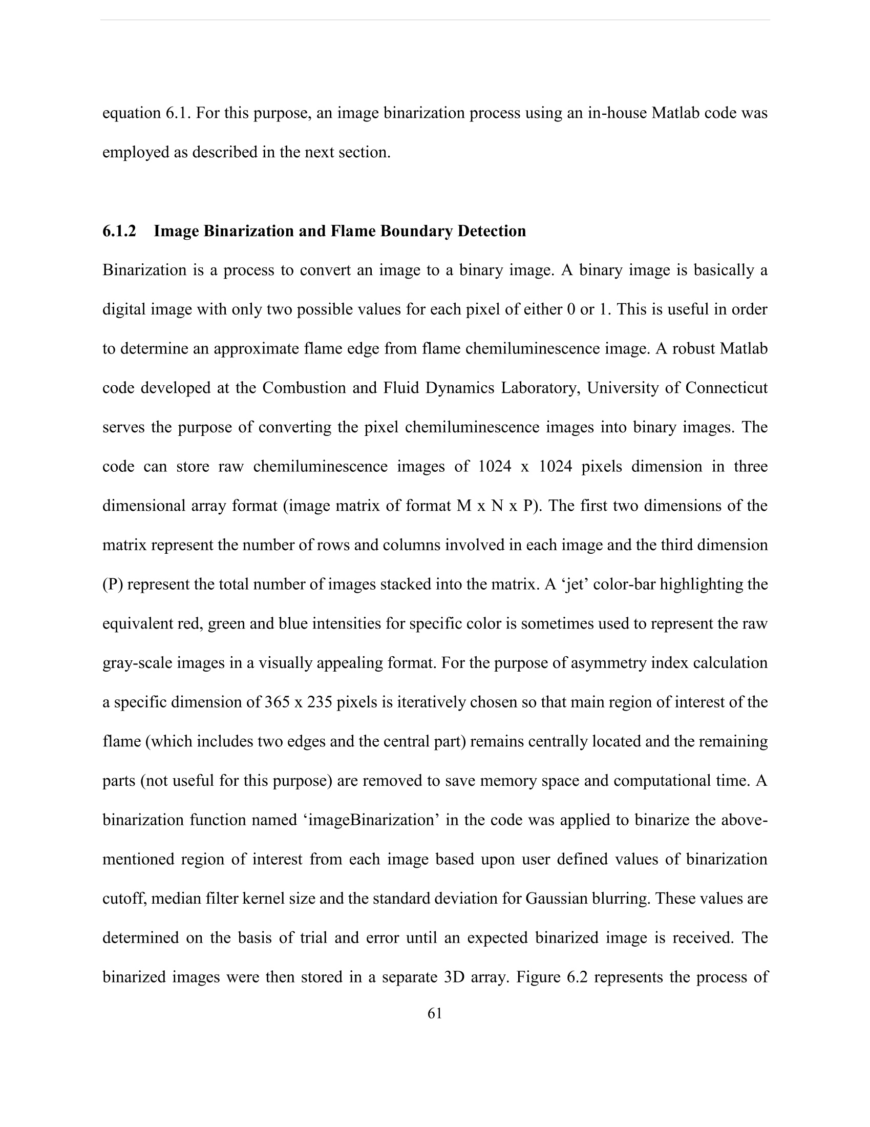
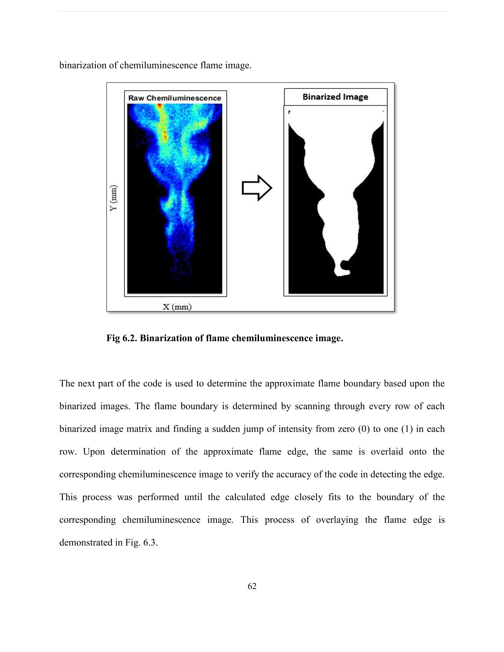
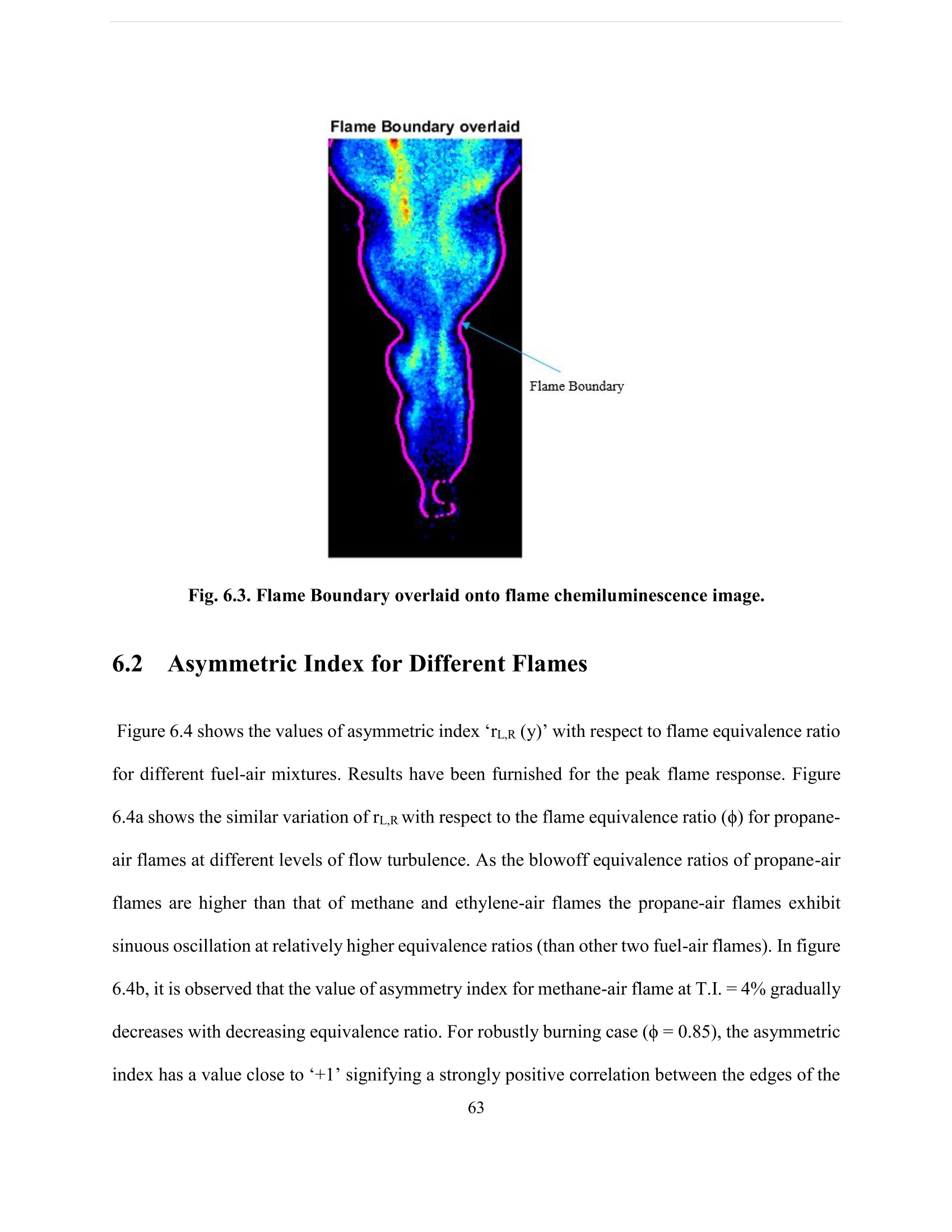
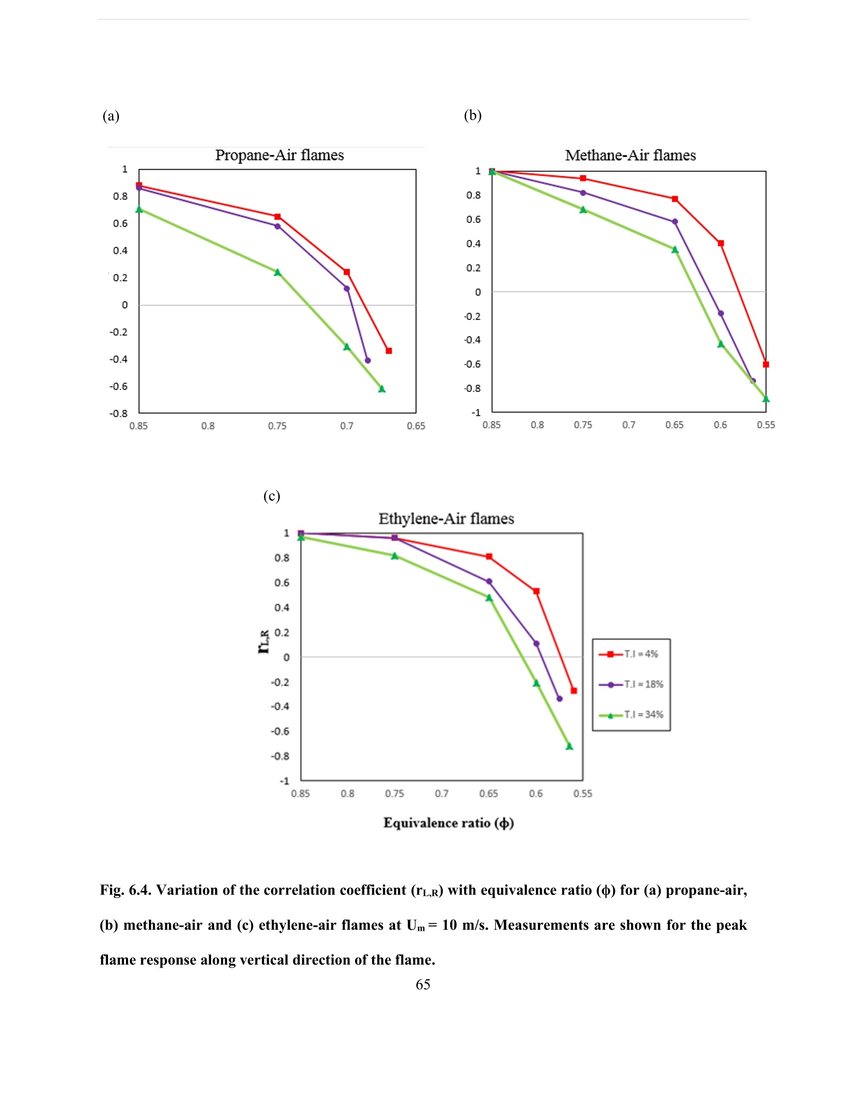
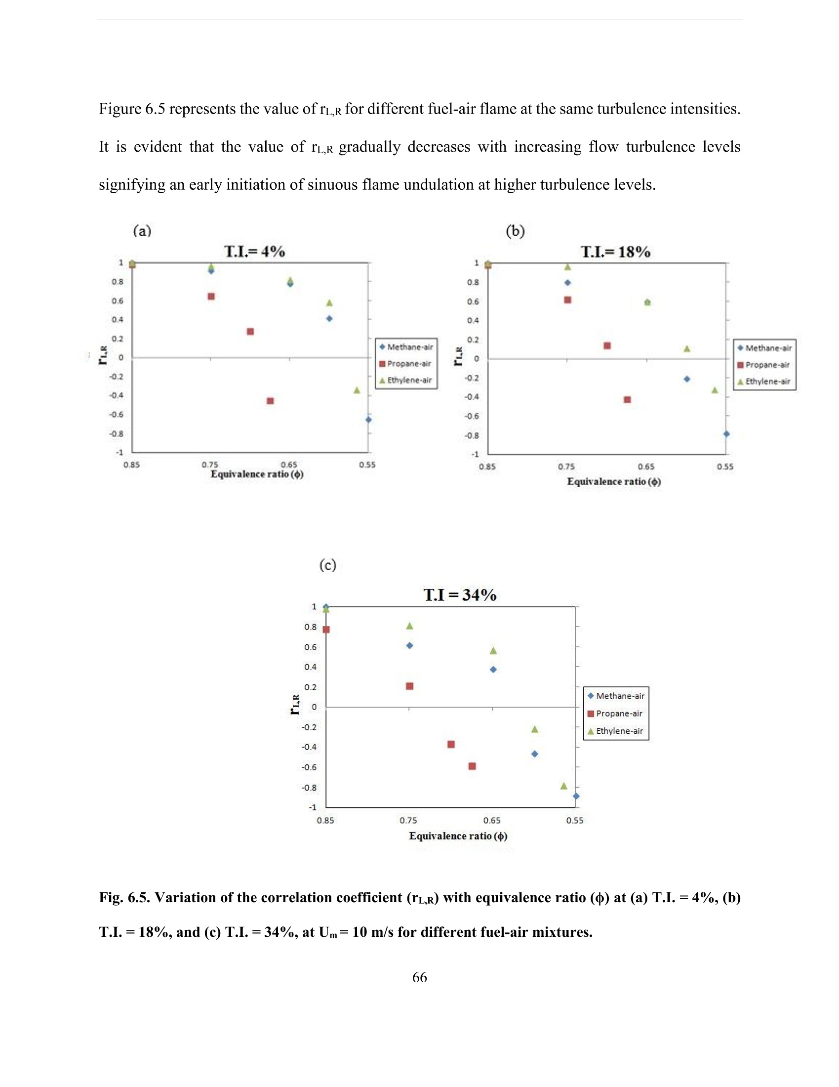
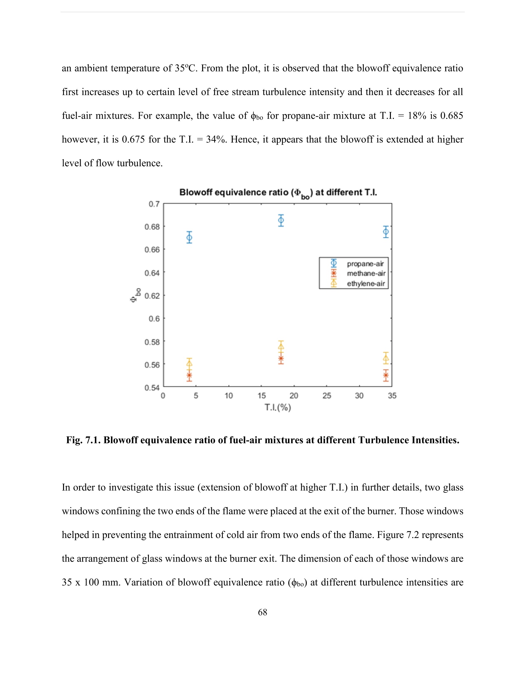
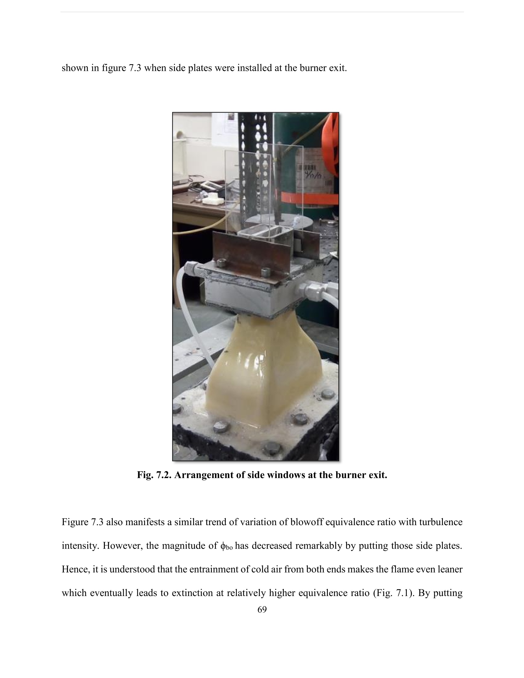
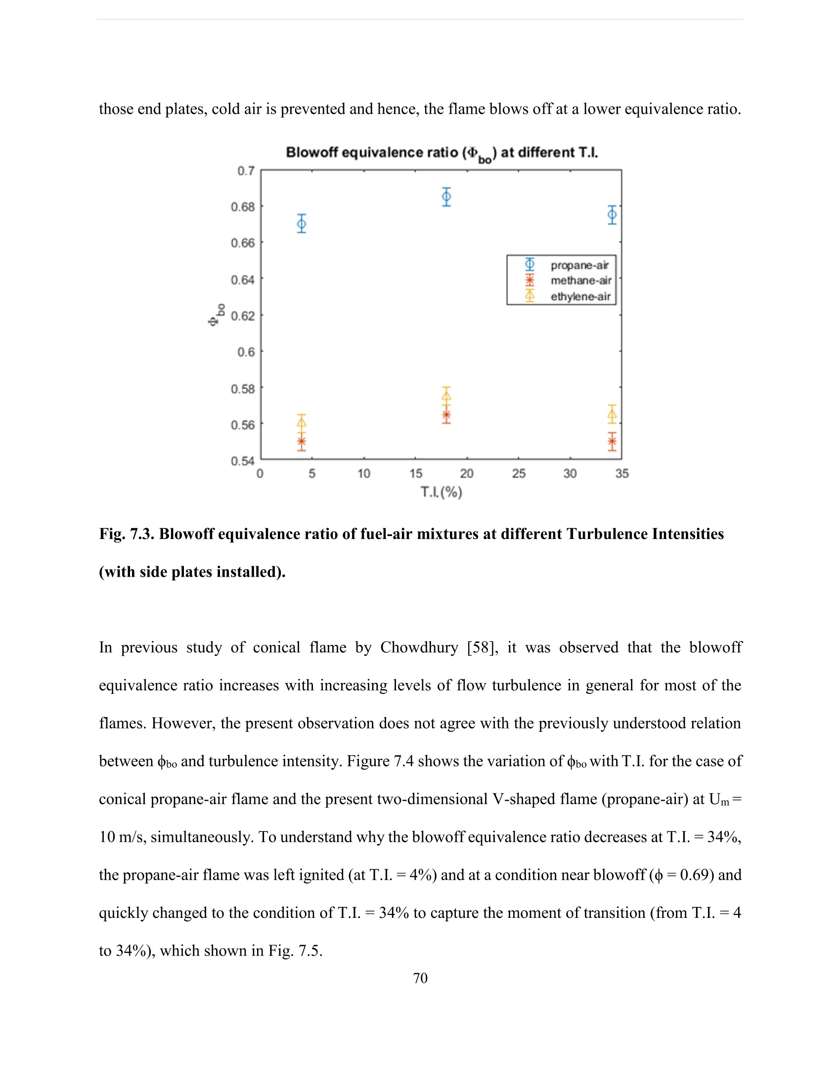
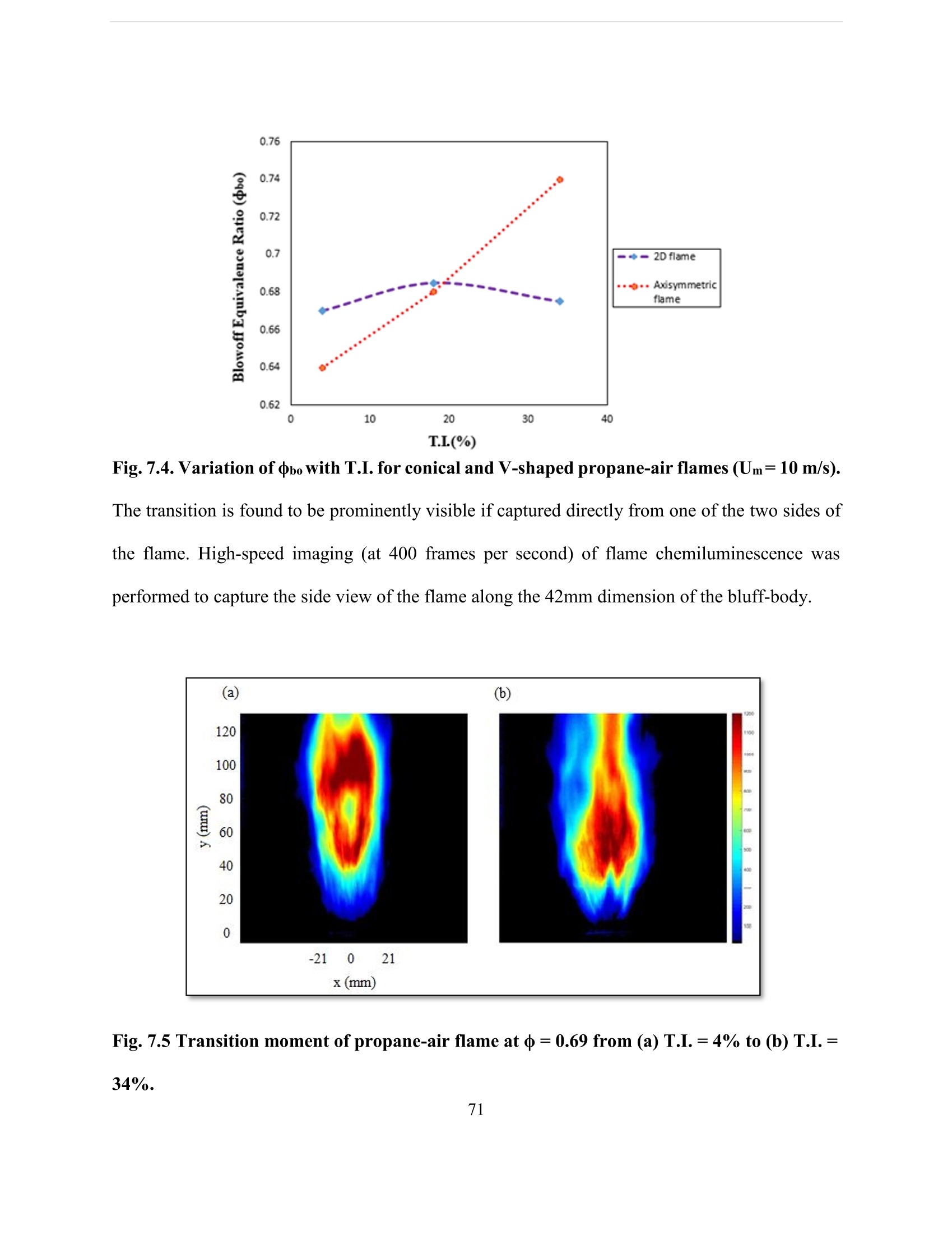
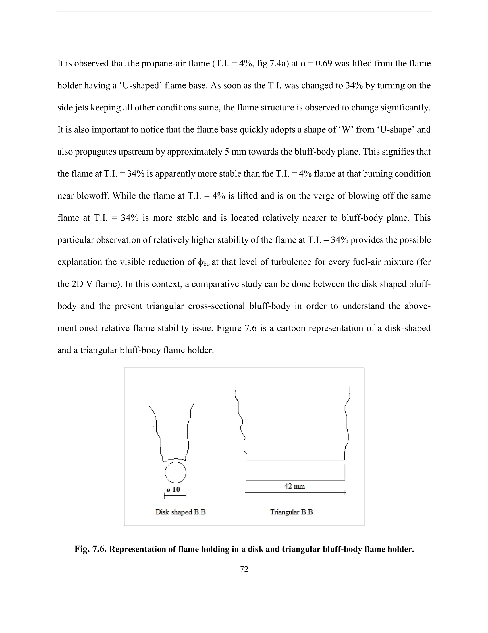

还剩98页未读,是否继续阅读?

产品配置单


北京欧兰科技发展有限公司为您提供《湍流预混火焰中动力学与吹脱特性检测方案(CCD相机)》,该方案主要用于其他中动力学与吹脱特性检测,参考标准--,《湍流预混火焰中动力学与吹脱特性检测方案(CCD相机)》用到的仪器有德国LaVision PIV/PLIF粒子成像测速场仪、LaVision DaVis 智能成像软件平台
推荐专场


相关方案
更多
该厂商其他方案
更多