


光催化制氢是利用太阳能获取氢能的重要途径,是当前研究热点。长期以来,人们致力于各种新型可见光光催化制氢材料的研究并取得较大进展。光解催化分解水所产生的氢气的效率与体系中的氢气浓度成一定的相关性,本研究应用了unisense氢气微电极测试PEC电池中的铂阴极密闭空间产生的氢气的量计算PEC电池的制氢效率,unsisense微电极测试氢响应速度很快,实现了对于PEC电池光电催化分解水产氢的实时监测。
方案详情

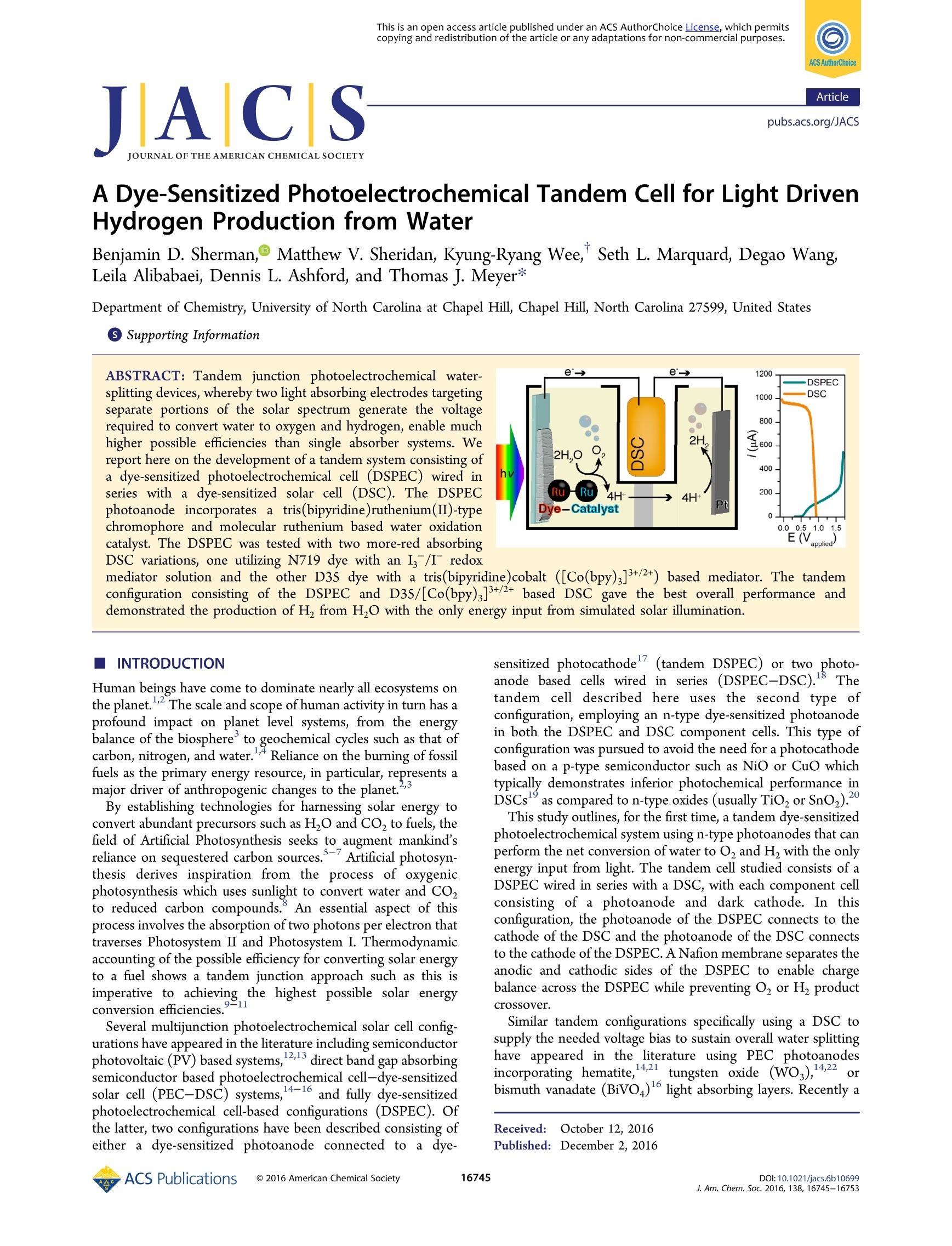
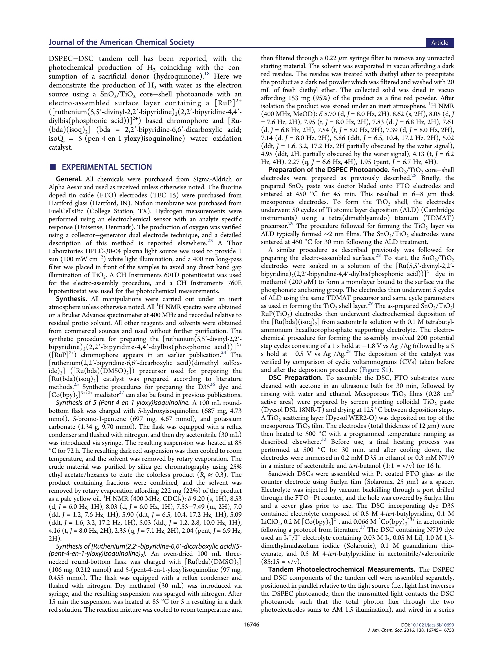
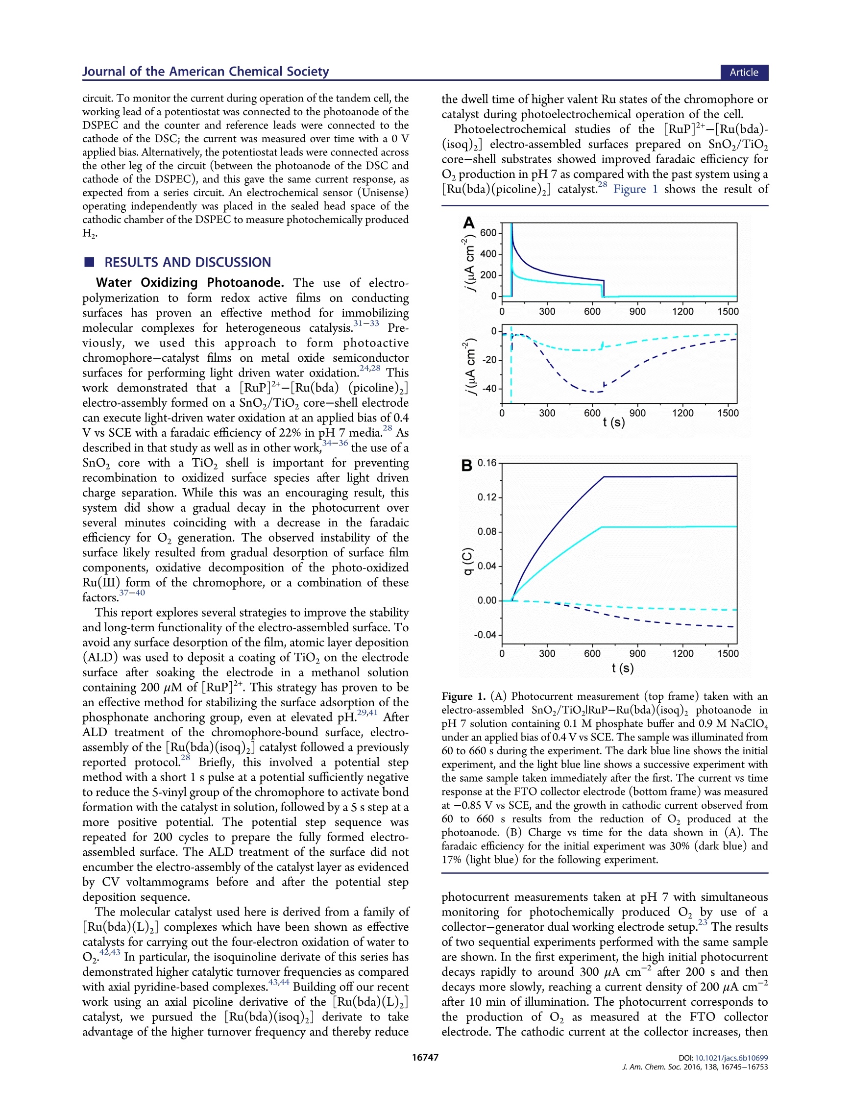
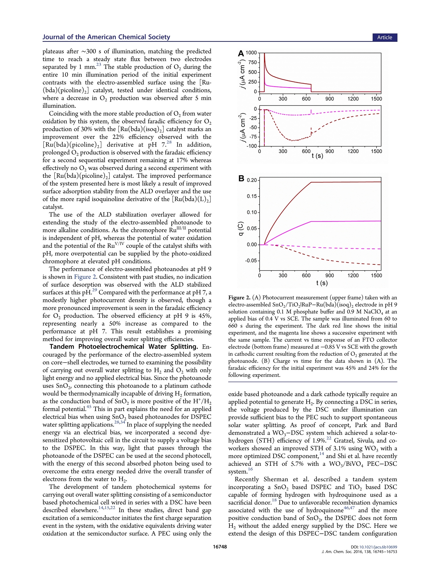
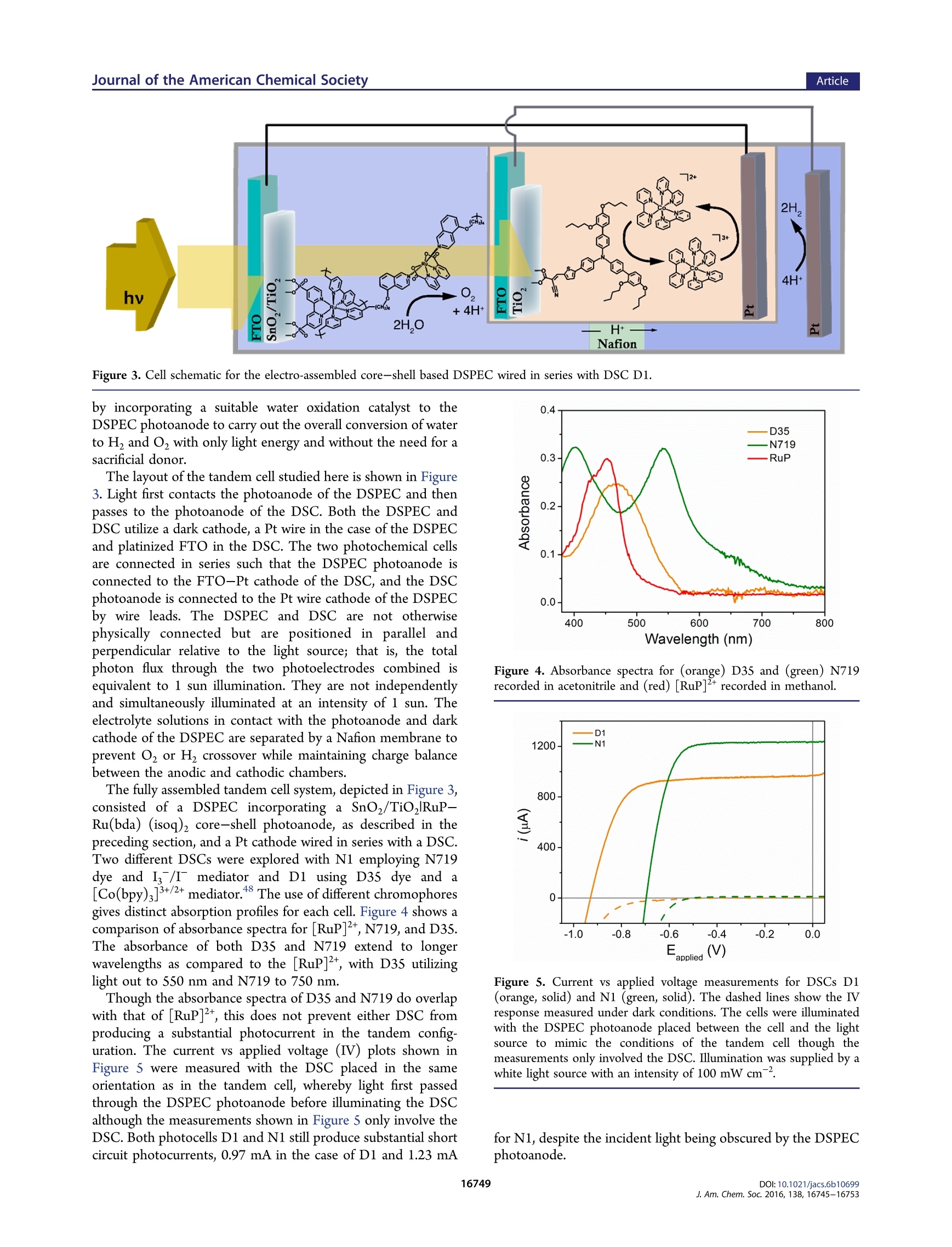
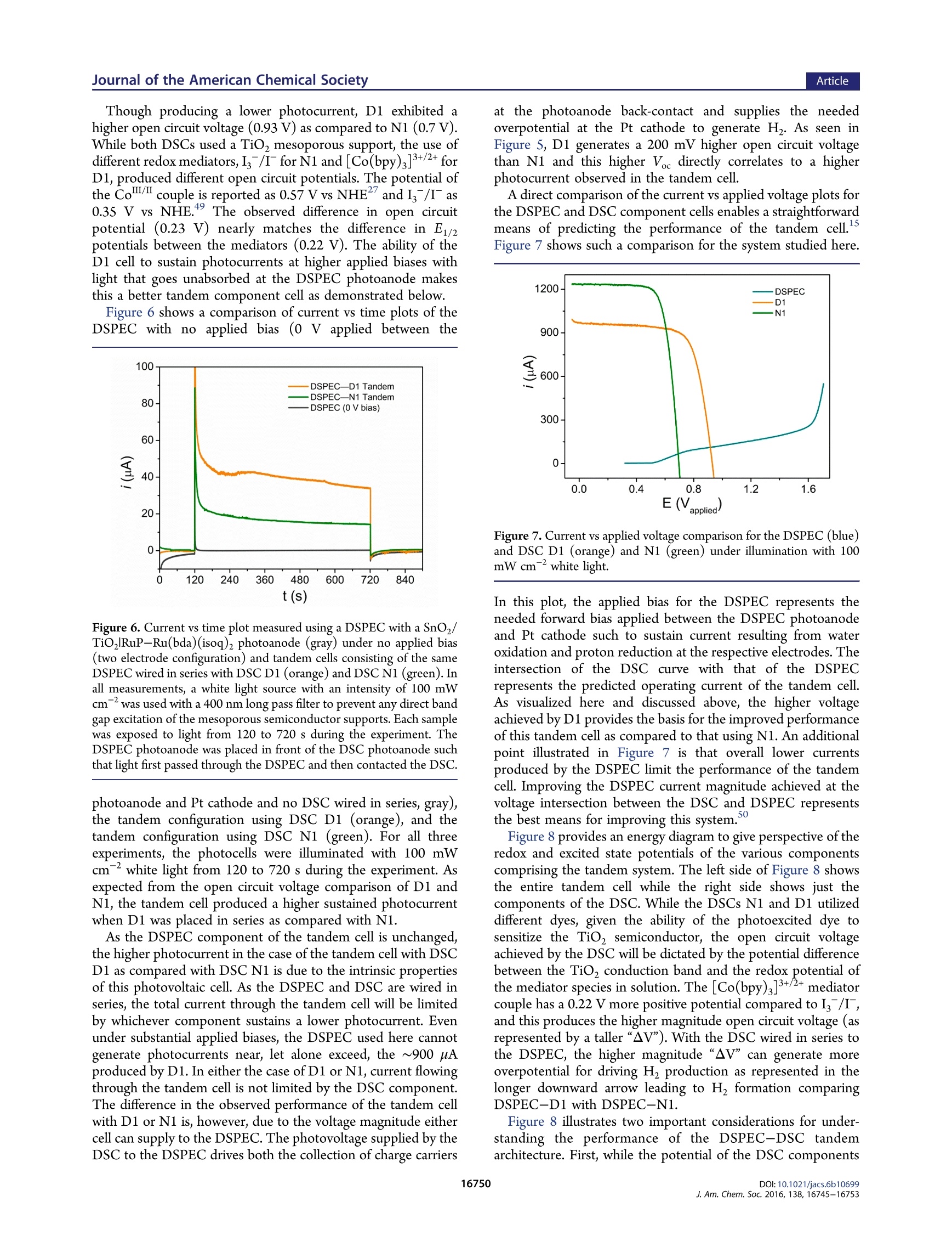
This is an open access article published under an ACS AuthorChoice License, which permitscopying and redistribution of the article or any adaptations for non-commercial purposes. ArticleJournal of the American Chemical Society pubs.acs.org/JACS A Dye-Sensitized Photoelectrochemical Tandem Cell for Light DrivenHydrogen Production from Water Benjamin D. Sherman, MMaatttthhew V. Sheridan, Kyung-Ryang Wee, Seth L. Marquard, Degao Wang,Leila Alibabaei, Dennis L. Ashford, and Thomas J. Meyer* Department of Chemistry, University of North Carolina at Chapel Hill, Chapel Hill, North Carolina 27599, United States Supporting Information ABSTRACT: Tandem junction photoelectrochemical water-splitting devices, whereby two light absorbing electrodes targetingseparate portions of the solar spectrum generate the voltagerequired to convert water to oxygen and hydrogen, enable muchhigher possible efficiencies than single absorber systems. Wereport here on the development of a tandem system consisting ofa dye-sensitized photoelectrochemical cell (DSPEC) wired inseries with a dye-sensitized solar cell (DSC). The DSPECphotoanode incorporates a t26ris(bipyridine)ruthenium(II)-typechromophore and molecular ruthenium based water oxidationcatalyst. The DSPEC was tested with two more-red absorbingDSC variations, one utilizing N719 dye with an Is/I redox INTRODUCTION Human beings have come to dominate nearly all ecosystems onthe planet.The scale and scope of human activity in turn has aprofound impact on planet level systems, from the energybalance of the biosphereto geochemical cycles such as that ofcarbon, nitrogen, and water. Reliance on the burning of fossilfuels as the primary energy resource, in particular, represents amajor driver of anthropogenic changes to the planet.,3 By establishing technologies for harnessing solar energy toconvert abundant precursors such as H,O and CO to fuels, thefield of Artificial Photosynthesis seeks to augment mankind'sreliance on sequestered carbon sources. Artificial photosyn-thesis derives inspiration from the process of oxygenicphotosynthesis which uses sunlight to convert water and CO,to reduced carbon compounds. An essential aspect of thisprocess involves the absorption of two photons per electron thattraverses Photosystem II and Photosystem I. Thermodynamicaccounting of the possible efficiency for converting solar energyto a fuel shows a tandem junction approach such as this isimperative to achieving the highest possible solar energyconversion efficiencies.-11 Several multijunction photoelectrochemical solar cell config-urations have appeared in the literature including semiconductorphotovoltaic (PV) based systems, 12,13 direct band gap absorbingsemiconductor based photoelectrochemical cell-dye-sensitizedsolar cell (PEC-DSC) systems, 4-16 and fully dye-sensitizedphotoelectrochemical cell-based configurations (DSPEC). Ofthe latter, two configurations have been described consisting ofeither a dye-sensitized photoanode connected to a dye- sensitized photocathode (tandem DSPEC) or two photo-anode based cells wired in series (DSPEC-DSC).18 Thetandem cell described here uses the second type ofconfiguration, employing an n-type dye-sensitized photoanodein both the DSPEC and DSC component cells. This type ofconfiguration was pursued to avoid the need for a photocathodebased on a p-type semiconductor such as NiOor CuO whichtypically demonstrates inferior photochemical performance inDSCs as compared to n-type oxides (usually TiO, or SnO2). This study outlines, for the first time, a tandem dye-sensitizedphotoelectrochemical system using n-type photoanodes that canperform the net conversion of water to O and H with the onlyenergy input from light. The tandem cell studied consists of aDSPEC wired in series with a DSC, with each component cellconsisting of a photoanode and dark cathode. In thisconfiguration, the photoanode of the DSPEC connects to thecathode of the DSC and the photoanode of the DSC connectsto the cathode of the DSPEC. A Nafion membrane separates theanodic and cathodic sides of the DSPEC to enable chargebalance across the DSPEC while preventing O2 or H productcrossover. Similar tandem configurations specifically using a DSC tosupply the needed voltage bias to sustain overall water splittinghave appeared in the literature using PEC photoanodesincorporating hematite, 4,21tungsten oxide (WO;), 4,22orbismuth vanadate (BiVO4) light absorbing layers. Recently a ( Rece i v e d:L: October 1 2, 2016 ) ( P ub lished: December 2, 2016 ) DSPEC-DSC tandem cell has been reported, with thephotochemical production of H coinciding with the con-sumption of a sacrificial donor (hydroquinone).18 Here wedemonstrate the production of H with water as the electronsource using a SnOz/TiO, core-shell photoanode with anelectro-assembled surface layer containing a [RuP]2+([ruthenium(5,S'-divinyl-2,2'-bipyridine)2(2,2'-bipyridine-4,4’-diylbis(phosphonic acid))]+) based chromophore and [Ru-(bda)(isoq)2] (bda =2,2'-bipyridine-6,6'-dicarboxylic acid;isoQ=S-(pen-4-en-1-yloxy)isoquinoline) water oxidationcatalyst. EXPERIMENTAL SECTION General. All chemicals were purchased from Sigma-Aldrich orAlpha Aesar and used as received unless otherwise noted. The fluorinedoped tin oxide (FTO) electrodes (TEC 15) were purchased fromHartford glass (Hartford, IN). Nafion membrane was purchased fromFuelCellsEtc (College Station, TX). Hydrogen measurements wereperformed using an electrochemical sensor with an analyte specificresponse (Unisense,Denmark).The production of oxygen was verifiedusing a collector-generator dual electrode technique, and a detaileddescription of this method is reported elsewhere.23 A ThorLaboratories HPLC-30-04 plasma light source was used to provide 1sun (100 mW cm) white light illumination, and a 400 nm long-passfilter was placed in front of the samples to avoid any direct band gapillumination of TiOz. A CH Instruments 601D potentiostat was usedfor the electro-assembly procedure, and a CH Instruments 760Ebipotentiostat was used for the photochemical measurements. Synthesis. All manipulations were carried out under an inertatmosphere unless otherwise noted.All HNMR spectra were obtainedon a Bruker Advance spectrometer at 400 MHz and recorded relative toresidual protio solvent. All other reagents and solvents were obtainedfrom commercial sources and used without further purification. Thesynthetic procedure for preparing the [ruthenium(5,5'-divinyl-2,2'-bipyridine)2(2,2'-bipyridine-4,4’'-diylbis(phosphonic acid))]([RuP]?+) chromophore appears in an earlier publication.4 The[ruthenium(2,2'-bipyridine-6,6'-dicarboxylic acid)(dimethyl sulfox-ide)z] ([Ru(bda)(DMSO),]) precursor used for preparing the[Ru(bda)(isoq)2] catalyst was prepared according to literaturemethods.Synthetic procedures for preparing the D352 dye and[Co(bpy)3]3+/2+ mediator can also be found in previous publications. Synthesis of 5-(Pent-4-en-1-yloxy)isoquinoline. A 100 mL round-bottom flask was charged with S-hydroxyisoquinoline (687 mg, 4.73mmol), S-bromo-1-pentene (697 mg, 4.67 mmol), and potassiumcarbonate (1.34 g, 9.70 mmol). The flask was equipped with a refluxcondenser and flushed with nitrogen, and then dry acetonitrile (30 mL)was introduced via syringe. The resulting suspension was heated at 85°C for 72 h. The resulting dark red suspension was then cooled to roomtemperature, and the solvent was removed by rotary evaporation. Thecrude material was purified by silica gel chromatography using 25%ethyl acetate/hexanes to elute the colorless product (R~ 0.3). Theproduct containing fractions were combined, and the solvent wasremoved by rotary evaporation affording 222 mg (22%) of the productas a pale yellow oil. H NMR (400 MHz, CDCl): 6 9.20 (s, 1H), 8.53(d, J=6.0 Hz, 1H), 8.03 (d,J=6.0 Hz, 1H), 7.55-7.49 (m, 2H), 7.0(dd,J=1.2, 7.6 Hz, 1H), 5.90 (ddt, J=6.5, 10.4, 17.2 Hz, 1H), 5.09(ddt, J= 1.6, 3.2, 17.2 Hz, 1H), 5.03 (ddt,J=1.2, 2.8, 10.0 Hz, 1H),4.16 (t,J=8.0 Hz, 2H), 2.35 (q,J=7.1Hz, 2H), 2.04 (pent, J=6.9 Hz,2H). Synthesis of [Ruthenium(2,2'-bipyridine-6,6'-dicarboxylic acid)(5-(pent-4-en-1-y/oxy)isoquinoline)]. An oven-dried 100 mL three-necked round-bottom flask was charged with [Ru(bda)(DMSO)](106 mg, 0.212 mmol) and 5-(pent-4-en-1-yloxy)isoquinoline (97 mg,0.455 mmol). The flask was equipped with a reflux condenser andflushed with nitrogen. Dry methanol (30 mL) was introduced viasyringe, and the resulting suspension was sparged with nitrogen. After15 min the suspension was heated at 85 °C for 5 h resulting in a darkred solution. The reaction mixture was cooled to room temperature and then filtered through a 0.22 um syringe filter to remove any unreactedstarting material. The solvent was evaporated in vacuo affording a darkred residue. The residue was treated with diethyl ether to precipitatethe product as a dark red powder which was filtered and washed with 20mL of fresh diethyl ether. The collected solid was dried in vacuoaffording 153 mg(95%) of the product as a fine red powder. Afterisolation the product was stored under an inert atmosphere. H NMR(400 MHz,MeOD):88.70 (d,J=8.0 Hz, 2H), 8.62(s,2H),8.05 (d, J=7.6 Hz, 2H), 7.95 (t, J=8.0 Hz, 2H), 7.83 (d,J=6.8 Hz, 2H), 7.61(d, J=6.8 Hz, 2H), 7.54 (t, J=8.0 Hz, 2H), 7.39(d,J=8.0 Hz, 2H),7.14 d, J=8.0 Hz, 2H), 5.86 (ddt, J=6.5, 10.4, 17.2 Hz, 2H), 5.02(ddt, J= 1.6, 3.2, 17.2 Hz, 2H partially obscured by the water signal),4.95 (ddt, 2H, partially obscured by the water signal), 4.13 (t,J=6.2Hz,4H), 2.27 (q, J= 6.6 Hz, 4H), 1.95 (pent, J= 6.7 Hz, 4H). Preparation of the DSPEC Photoanode. SnOz/TiO core-shellelectrodes were prepared as previously described. Briefly, theprepared SnO2 paste was doctor bladed onto FTO electrodes andsintered at 450 °C for 45 min. This resulted in 6-8 um thickmesoporous electrodes. To form the TiO, shell, the electrodesunderwent 50 cycles of Ti atomic layer deposition (ALD) (Cambridgeinstruments) using a tetra(dimethlyamido) titanium (TDMAT)precursor. The procedure followed for forming the TiO, layer viaALD typically formed ~2 nm films. The SnO,/TiO, electrodes weresintered at 450°C for 30 min following the ALD treatment. A similar procedure as described previously was followed forpreparing the electro-assembled surfaces.8 To start, the SnO,/TiO,electrodes were soaked in a solution of the [Ru(5,S'-divinyl-2,2'-bipyridine)2(2,2'-bipyridine-4,4’-diylbis(phosphonic acid))]2+dye inmethanol (200 pM) to form a monolayer bound to the surface via thephosphonate anchoring group. The electrodes then underwent 5 cyclesof ALD using the same TDMAT precursor and same cycle parametersas used in forming the TiO, shell layer.The as-prepared SnOz/TiO,RuP(TiOz) electrodes then underwent electrochemical deposition ofthe [Ru(bda)(isoq)2] from acetonitrile solution with 0.1 M tetrabutyl-ammonium hexafluorophosphate supporting electrolyte. The electro-chemical procedure for forming the assembly involved 200 potentialstep cycles consisting of a 1 s hold at -1.8 V vs Ag*/Ag followed by a 5s hold at -0.5 V vs Ag*/Ag. The deposition of the catalyst wasverified by comparison of cyclic voltammograms (CVs) taken beforeand after the deposition procedure (Figure S1). DSC Preparation. To assemble the DSC, FTO substrates werecleaned with acetone in an ultrasonic bath for 30 min, followed byrinsing with water and ethanol. Mesoporous TiO, films (0.28cm"active area) were prepared by screen printing colloidal TiO2 paste(Dyesol DSL 18NR-T) and drying at 125 °C between deposition steps.A TiO, scattering layer (Dyesol WER2-O) was deposited on top of themesoporous TiO, film. The electrodes (total thickness of 12 um) werethen heated to S00 C with a programmed temperature ramping asdescribed elsewhere. Before use, a final heating process wasperformed at 500℃ for 30 min, and after cooling down, theelectrodes were immersed in 0.2 mM D35 in ethanol or 0.3 mMN719in a mixture of acetonitrile and tert-butanol(1:1=v/v) for 16 h. Sandwich DSCs were assembled with Pt coated FTO glass as thecounter electrode using Surlyn film (Solaronix, 25 um) as a spacer.Electrolyte was injected by vacuum backfilling through a port drilledthrough the FTO-Pt counter, and the hole was covered by Surlyn filmand a cover glass prior to use. The DSC incorporating dye D35contained electrolyte composed of 0.8 M 4-tert-butylpyridine, 0.1 MLiClo4, 0.2 M [Co(bpy)3]", and 0.066 M [Co(bpy)3] in acetonitrilefollowing a protocol from literature.The DSC containing N719 dyeused an I/I electrolyte containing 0.03 M I, 0.05 M LiI, 1.0 M 1,3-dimethylimidazolium iodide (Solaronix), 0.1 M guanidinium thio-cyanate, and 0.5 M 4-tert-butylpyridine in acetonitrile/valeronitrile(85:15=v/v). Tandem Photoelectrochemical Measurements. The DSPECand DSC components of the tandem cell were assembled separately,positioned in parallel relative to the light source (i.e., light first traversesthe DSPEC photoanode, then the transmitted light contacts the DSCphotoanode such that the total photon flux through the twophotoelectrodes sums to AM 1.5 illumination), and wired in a series circuit. To monitor the current during operation of the tandem cell, theworking lead of a potentiostat was connected to the photoanode of theDSPEC and the counter and reference leads were connected to thecathode of the DSC; the current was measured over time with a 0 Vapplied bias. Alternatively, the potentiostat leads were connected acrossthe other leg of the circuit (between the photoanode of the DSC andcathode of the DSPEC), and this gave the same current response, asexpected from a series circuit. An electrochemical sensor (Unisense)operating independently was placed in the sealed head space of thecathodic chamber of the DSPEC to measure photochemically producedH2. RESULTS AND DISCUSSION Water Oxidizing Photoanode. The use of electro-polymerization to form redox active films on conductingsurfaces has proven an effective method for immobilizingmolecular complexes for heterogeneous catalysis. 1-3P3re-viously, we used this approach to form photoactivechromophore-catalyst films on metal oxide semiconductorsurfaces for performing light driven water oxidation.24,28 Thiswork demonstrated that a[RuP]2+-[Ru(bda) (picoline)]electro-assembly formed on a SnO/TiO2 core-shell electrodecan execute light-driven water oxidation at an applied bias of 0.4V vs SCE with a faradaic efficiency of 22% in pH 7 media.28 Asdescribed in that study as well as in other work,34-36 the use of aSnO, core with a TiO, shell is important for preventingrecombination to oxidized surface species after light drivencharge separation. While this was an encouraging result, thissystem did show a gradual decay in the photocurrent overseveral minutes coinciding with a decrease in the faradaicefficiency for O generation. The observed instability of thesurface likely resulted from gradual desorption of surface filmcomponents, oxidative decomposition of the photo-oxidizedRu(III) form of the chromophore, or a combination of thesefactors.37-40 This report explores several strategies to improve the stabilityand long-term functionality of the electro-assembled surface. Toavoid any surface desorption of the film, atomic layer deposition(ALD) was used to deposit a coating of TiO, on the electrodesurface after soaking the electrode in a methanol solutioncontaining 200 uM of [RuP]2+. This strategy has proven to bean effective method for stabilizing the surfacee aaddssoorprzp9t,i4o1n ooff thephosphonate anchoring group,even at elevated pH.2941 AfterALD treatment of the chromophore-bound surface, electro-assembly of the [Ru(bda)(isoq)z] catalyst followed a previouslyreported protocol.28 Briefly, this involved a potential stepmethod with a short 1 s pulse at a potential sufficiently negativeto reduce the S-vinyl group of the chromophore to activate bondformation with the catalyst in solution, followed by a S s step at amore positive potential. The potential step sequence wasrepeated for 200 cycles to prepare the fully formed electro-assembled surface. The ALD treatment of the surface did notencumber the electro-assembly of the catalyst layer as evidencedby CV voltammograms before and after the potential stepdeposition sequence. The molecular catalyst used here is derived from a family of[Ru(bda)(L)2] complexes which have been shown as effectivecatalysts for carrying out the four-electron oxidation of water toO,4243 In particular, the isoquinoline derivate of this series hasdemonstrated higher catalytic turnover frequencies as comparedwith axial pyridine-based complexes43,44 Building off our recentwork using an axial picoline derivative of the [Ru(bda)(L)2]catalyst, we pursued the [Ru(bda)(isoq)2] derivate to takeadvantage of the higher turnover frequency and thereby reduce the dwell time of higher valent Ru states of the chromophore orcatalyst during photoelectrochemical operation of the cell. Photoelectrochemical studies of the [RuP]2+-[Ru(bda)-(isoq)2] electro-assembled surfaces prepared on SnOz/TiO,core-shell substrates showed improved faradaic efficiency forOzproduction in pH 7 as compared with the past system using a[Ru(bda)(picoline)z] catalyst. Figure 1 shows the result of Figure 1. (A) Photocurrent measurement (top frame) taken with anelectro-assembled SnOz/TiORuP-Ru(bda)(isoq)2 photoanode inpH 7 solution containing 0.1 M phosphate buffer and 0.9 M NaClO4under an applied bias of 0.4 V vs SCE. The sample was illuminated from60 to 660 s during the experiment. The dark blue line shows the initialexperiment, and the light blue line shows a successive experiment withthe same sample taken immediately after the first. The current vs timeresponse at the FTO collector electrode (bottom frame) was measuredat -0.85 Vvs SCE,and the growth in cathodic current observed from60 to 660 s results from the reduction of O produced at thephotoanode. (B) Charge vs time for the data shown in (A). Thefaradaic efficiency for the initial experiment was 30% (dark blue) and17% (light blue) for the following experiment. photocurrent measurements taken at pH 7 with simultaneousmonitoring for photochemically produced o, by use of acollector-generator dual working electrode setup. The resultsof two sequential experiments performed with the same sampleare shown. In the first experiment, the high initial photocurrentdecays rapidly to around 300 uA cm after 200 s and thendecays more slowlmt1y, reaching a current density of 200 uA cmafter 10 min of illumination. The photocurrent corresponds tothe production of O2 as measured at the FTO collectorelectrode. The cathodic current at the collector increases, then plateaus after ~300 s of illumination, matching the predictedtime to reach a steady state flux between two electrodesseparated by 1 mm. The stable production of O during theentire 10 min illumination period of the initial experimentcontrasts with the electro-assembled surface using the [Ru-(bda)(picoline)2] catalyst, tested under identical conditions,where a decrease in O, production was observed after 5 minillumination. Coinciding with the more stable production ofO, from wateroxidation by this system, the observed faradic efficiency for O2production of 30% with the [Ru(bda)(isoq)2] catalyst marks animprovement over the 22% efficiency observed with the[Ru(bda)(picoline)] derivative at pH 7.28 In addition,prolonged Oz production is observed with the faradaic efficiencyfor a second sequential experiment remaining at 17% whereaseffectively no O, was observed during a second experiment withthe [Ru(bda)(picoline)2] catalyst. The improved performanceof the system presented here is most likely a result of improvedsurface adsorption stability from the ALD overlayer and the useof the more rapid isoquinoline derivative of the [Ru(bda)(L)z]catalyst. The use of the ALD stabilization overlayer allowed forextending the study of the electro-assembled photoanode tomore alkaline conditions. As the chromophore Ru""/l potentialis independent of pH, whereas the potential of water oxidationand t.hteh potential of the Rui couple of the catalyst shifts withpH, more overpotential can be supplied by the photo-oxidizedchromophore at elevated pH conditions. The performance ofelectro-assembled photoanodes at pH 9is shown in Figure 2. Consistent with past studies, no indicationof surface desorption was observed with the ALD stabilizedsurfaces at this pH. Compared with the performance at pH 7, amodestly higher photocurrent density is observed, though amore pronounced improvement is seen in the faradaic efficiencyfor O2 production. The observed efficiency at pH 9 is 45%,representing nearly a 50% increase as compared to theperformance at pH 7. This result establishes a promisingmethod for improving overall water splitting efficiencies. Tandem Photoelectrochemical Water Splitting. En-couraged by the performance of the electro-assembled systemon core-shell electrodes, we turned to examining the possibilityof carrying out overall water splitting to H and O with onlylight energy and no applied electrical bias. Since the photoanodeuses SnO2, connecting this photoanode to a platinum cathodewould be thermodynamically incapable of driving H formation,as the conduction band of SnO, is more positive of the H/Hformal potential. This in part explains the need for an appliedelectrical bias when using SnO, based photoanodes for DSPECwater splitting applications.28,34 In place of supplying the neededenergy via an electrical bias, we incorporated a second dye-sensitized photovoltaic cell in the circuit to supply a voltage biasto the DSPEC. In this way, light that passes through thephotoanode of the DSPEC can be used at the second photocell,with the energy of this second absorbed photon being used toovercome the extra energy needed drive the overall transfer ofelectrons from the water to H. The development of tandem photochemical systems forcarrying out overall water splitting consisting of a semiconductorbased photochemical cell wired in series with a DSC have beendescribed elsewhere.14,15,22 In these studies, direct band gapexcitation of a semiconductor initiates the first charge separationevent in the system, with the oxidative equivalents driving wateroxidation at the semiconductor surface. A PEC using only the Figure 2. (A) Photocurrent measurement (upper frame) taken with anelectro-assembled SnO,/TiO,RuP-Ru(bda)(isoq), electrode in pH9solution containing 0.1 M phosphate buffer and 0.9 M NaClo at anapplied bias of0.4 V vs SCE. The sample was illuminated from 60 to660 s during the experiment. The dark red line shows the initialexperiment, and the magenta line shows a successive experiment withthe same sample. The current vs time response of an FTO collectorelectrode (bottom frame)measured at -0.85 V vs SCE with the growthin cathodic current resulting from the reduction of O2 generated at thephotoanode. (B) Charge vs time for the data shown in (A). Thefaradaic efficiency for the initial experiment was 45% and 24% for thefollowing experiment. oxide based photoanode and a dark cathode typically require anapplied potential to generate H. By connecting a DSC in series,the voltage produced by the DSC under illumination canprovide sufficient bias to the PEC such to support spontaneoussolar water splitting. As proof of concept, Park and Barddemonstrated a WO3-DSC system which achieved a solar-to-hydrogen (STH) efficiency of 1.9%." Gratzel, Sivula, and co-workers showed an improved STH of 3.1% using WO with amore optimized DSC component,and Shi et al. have recentlyachieved an STH of 5.7% with a WO/BiVO4 PEC-DSC16system. Recently Sherman et al. described a tandem systemincorporating a SnO based DSPEC and TiO, based DSCcapable of forming hydrogen with hydroquinone used as asacrificial donor.Due to unfavorable recombination dynamicsassociated with the use of hydroquinone46,47 and the morepositive conduction band of SnO, the DSPEC does not formH, without the added energy supplied by the DSC. Here weextend the design of this DSPEC-DSC tandem configuration Figure 3. Cell schematic for the electro-assembled core-shell based DSPEC wired in series with DSC D1. by incorporating a suitable water oxidation catalyst to theDSPEC photoanode to carry out the overall conversion of waterto H and O2 with only light energy and without the need for asacrificial donor. The layout of the tandem cell studied here is shown in Figure3. Light first contacts the photoanode of the DSPEC and thenpasses to the photoanode of the DSC. Both the DSPEC andDSC utilize a dark cathode, a Pt wire in the case of the DSPECand platinized FTO in the DSC. The two photochemical cellsare connected in series such that the DSPEC photoanode isconnected to the FTO-Pt cathode of the DSC, and the DSCphotoanode is connected to the Pt wire cathode of the DSPECby wire leads. The DSPEC and DSC are not otherwisephysically connected but are positioned in parallel andperpendicular relative to the light source; that is, the totalphoton flux through the two photoelectrodes combined isequivalent to 1 sun illumination. They are not independentlyand simultaneously illuminated at an intensity of 1 sun. Theelectrolyte solutions in contact with the photoanode and darkcathode ofthe DSPEC are separated by a Nafion membrane toprevent O2 or H, crossover while maintaining charge balancebetween the anodic and cathodic chambers. The fully assembled tandem cell system, depicted in Figure 3,consisted of a DSPEC incorporating a SnOz/TiO,RuP-Ru(bda) (isoq)2 core-shell photoanode, as described in thepreceding section, and a Pt cathode wired in series with a DSC.Two different DSCs were explored with N1 employing N719dye and I/I mediator and D1 using D35 dye and a[Co(bpy)3]3+/2+ mediator.48 The use of different chromophoresgives distinct absorption profiles for each cell. Figure 4 shows acomparison of absorbance spectra for [RuP]2t, N719, and D35.The absorbance of both D35 and N719 extend to longerwavelengths as compared to the [RuP]2t, with D35 utilizinglight out to 550 nm and N719 to 750 nm. Though the absorbance spectra of D35 and N719 do overlapwith that of [RuP]2t, this does not prevent either DSC fromproducing a substantial photocurrent in the tandem config-uration. The current vs applied voltage (ⅣV) plots shown inFigure 5 were measured with the DSC placed in the same1t1orientation as in the tandem cell, whereby light first passedthrough the DSPEC photoanode before illuminating the DSCalthough the measurements shown in Figure 5 only involve theDSC. Both photocells D1 and N1 still produce substantial shortcircuit photocurrents, 0.97 mA in the case of D1 and 1.23 mA Figure 4. Absorbance spectra for (orange) D35 and (green) N719recorded in acetonitrile and (red) [RuP]2+ recorded in methanol. Figure 5. Current vs applied voltage measurements for DSCs D1(orange, solid) and N1 (green, solid). The dashed lines show the Ⅳresponse measured under dark conditions. The cells were illuminatedwith the DSPEC photoanode placed between the cell and the lightsource to mimic the conditions of the tandem cell though themeasurements only involved the DSC. Illumination was supplied by awhite light source with an intensity of 100 mW cm. ( for N1, despite the incident light being obscured by the DSPEC photoanode. ) Though producing a lower photocurrent, D1 exhibited ahigher open circuit voltage (0.93 V) as compared to N1 (0.7V).While both DSCs used a TiO, mesoporous support, the use ofdifferent redox mediators,I/I for N1 and [Co(bpy)3]3+/2+ forD1, produced different open circuit potentials. The potential ofthe Col"l/lI couple is reported as 0.57 V vs NHE and I /I as0.35 V vs NHE.49 The observed difference in open circuitpotential (0.23 V) nearly matches the difference in E1/2potentials between the mediators (0.22 V). The ability of theD1 cell to sustain photocurrents at higher applied biases withlight that goes unabsorbed at the DSPEC photoanode makest1.1his a better tandem component cell as demonstrated below. Figure 6 shows a comparison of current vs time plots of theDSPEC with noapplied bias (0 V/aapplied between the Figure 6. Current vs time plot measured using a DSPEC with a SnO/TiO,RuP-Ru(bda)(isoq)2 photoanode (gray) under no applied bias(two electrode configuration) and tandem cells consisting of the sameDSPEC wired in series with DSC D1 (orange) and DSC N1 (green). Inall measurements, a white light source with an intensity of 100 mWcm-was used with a 400 nm long pass filter to prevent any direct bandgap excitation of the mesoporous semiconductor supports. Each samplewas exposed to light from 120 to 720 s during the experiment. TheDSPEC photoanode was placed in front of the DSC photoanode suchthat light first passed through the DSPEC and then contacted the DSC. photoanode and Pt cathode and no DSC wired in series, gray),the tandem configuration using DSC D1 (orange), and thetandem configuration using DSC N1 (green). For all threeexperiments, the photocells were illuminated with 100 mWcm white light from 120 to 720 s during the experiment. Asexpected from the open circuit voltage comparison of D1 andN1, the tandem cell produced a higher sustained photocurrentwhen D1 was placed in series as compared with N1. As the DSPEC component of the tandem cell is unchanged,the higher photocurrent in the case of the tandem cell with DSCD1 as compared with DSC N1 is due to the intrinsic propertiesof this photovoltaic cell. As the DSPEC and DSC are wired inseries, the total current through the tandem cell will be limitedby whichever component sustains a lower photocurrent. Evenunder substantial applied biases, the DSPEC used here cannotgenerate photocurrents near, let alone exceed, the ~900 uAproduced by D1. In either the case of D1 or N1, current flowingthrough the tandem cell is not limited by the DSC component.The difference in the observed performance of the tandem cellwith D1 or N1 is, however, due to the voltage magnitude eithercell can supply to the DSPEC. The photovoltage supplied by theDSC to the DSPEC drives both the collection of charge carriers at the photoanode back-contact and supplies the neededoverpotential at the Pt cathode to generate H. As seen inFigure 5, D1 generates a 200 mV higher open circuit voltagethan N1 and this higher V directly correlates to a higherphotocurrent observed in the tandem cell. A direct comparison of the current vs applied voltage plots forthe DSPEC and DSC component cells enables a straightforwardmeans of predicting the performance of the tandem cell.Figure 7 shows such a comparison for the system studied here. Figure 7. Current vs applied voltage comparison for the DSPEC (blue)and DSC D1 (orange) and N1 (green) under illumination with 100mW cm’white light In this plot, the applied bias for the DSPEC represents theneeded forward bias applied between the DSPEC photoanodeand Pt cathode such to sustain current resulting from wateroxidation and proton reduction at the respective electrodes. Theintersection of the DSC curve with that of the DSPECrepresents the predicted operating current of the tandem cell.As visualized here and discussed above, the higher voltageachieved by D1 provides the basis for the improved performanceof this tandem cell as compared to that using N1. An additionalpoint illustrated in Figure 7 is that overall lower currentsproduced by the DSPEC limit the performance of the tandemcell. Improving the DSPEC current magnitude achieved at thevoltage intersection between the DSC and DSPEC representsthe best means for improving this system. Figure 8 provides an energy diagram to give perspective of theredox and excited state potentials of the various componentscomprising the tandem system. The left side of Figure 8 showsthe entire tandem cell while the right side shows just thecomponents of the DSC. While the DSCs N1 and D1 utilizeddifferent dyes, given the ability of the photoexcited dye tosensitize the TiO semiconductor, the open circuit voltageachieved by the DSC will be dictated by the potential differencebetween the TiO, conduction band and the redox potential ofthe mediator species in solution. The [Co(bpy)s]3+/2+ mediatorcouple has a 0.22 V more positive potential compared to I/I ,and this produces the higher magnitude open circuit voltage (asrepresented by a taller“AV"). With the DSC wired in series tothe DSPEC, the higher magnitude“AV”can generate moreoverpotential for driving H2 production as represented in thelonger downward arrow leading to H formation comparingDSPEC-D1 with DSPEC-N1. Figure 8 illustrates two important considerations for under-standing the performance of the DSPEC-DSC tandemarchitecture. First, while the potential of the DSC components Figure 8. Energy diagram considering the various components of the tandem cell with DSPEC-D1 shown in the top frame and DSPEC-N1 in thebottom frame. The upward arrows represent the increase in potential upon formation of the photoexcited state. Downward arrows represent electrontransfer events, and the upward arrow in the box marked“AV" indicates the increase in electron energy as supplied by the DSC. The sequentialexcitation/electron transfer events follow as (1) excitation of the [RuP]2+chromophore;(2) electron injection from the excited state chromophore tothe SnOz/TiO2 core-shell oxide with the conduction band (CB) potential of SnOz indicated; (3) hole transfer from the oxidized chromophore to the[Ru(bda)(isoq)z] catalyst (four sequential hole transfers are required for each equivalent of O2 generated, and the potential of the Ru couple of thecatalyst is shown);(4) the photovoltage of the DSC increases the energy of electrons in the circuit with the details of the DSC shown to the rightincluding (4a) excitation of the DSC dye, (4b) electron injection to TiO, by the excited state dye, and (4c) hole transfer from the oxidized dye to thereduced form of the mediator (electrons from the DSPEC anode regenerate the reduced form of the mediator at the DSC cathode); and (5) formationof H, at the DSPEC cathode. vs an absolute scale as shown on the right side of Figure 8 areimportant for understanding the voltage produced by the DSCunder illumination, it is only the magnitude of this voltage andnot its placement vs the absolute scale, that matters inconsidering the operation of the tandem cell (as shown onthe left of Figure 8). In the same manner that two identicalbatteries, with the same anode/cathode chemistries, willgenerate 2× the voltage of the individual battery when thetwo are wired in series, the voltage produced by the DSC adds tothat of the DSPEC regardless of the absolute level of the TiO2conduction band in the DSC. Second, the voltage supplied bythe DSC contributes to the flow of current in the tandem cell byproviding bias both to collect charge carriers at the FTO-SnO,interface and to overcome the needed bias to drive H at the Ptcathode. The conduction band of SnOz in pH 8.8 solution is~400 mV positive of the thermodynamic potential of hydrogenformation4 which sets a lower limit for AV required from theDSC in order to sustain spontaneous current flow with thetandem cell under illumination. To verify that the observed photocurrents resulted from thenet formation of H, from water, for the DSPEC under noapplied bias and for the DSPEC-D1 tandem cell, the hydrogenconcentration in the headspace over the cathodic chamber of theDSPEC was monitored using an electrochemical probe with a specific response to H (Unisense, Denmark). The concen-tration of H in the cathode headspace was monitoredsimultaneously with the photocurrent measurements shown inFigure 6. As seen in Figures 6 and 9, the DSPEC under no Figure 9. Increase in [H2] as measured using an electrochemical sensorwith specific sensitivity to the presence of H. The probe was placed in asealed chamber housing the Pt cathode which was in ionic contact withthe chamber containing the photoanode. applied bias fails to sustain any photocurrent under prolongedillumination corresponding to no observed net increase in Hover the course of the experiment. This observation is consistentwith the ubiquitous need for applied bias in DSPEC studies inthe literature to sustain a measurable photocurrent den-sity.28,sI-s4It is also consistent with the thermodynamicconsequence of using a SnO, based photoanode as mentionedabove. In the case of the DSPEC-D1 tandem cell, the stablephotocurrent corresponds to a steady increase in the amount ofhydrogen detected in the sealed headspace of the anodicchamber of the DSPEC. Measurement of the amount of hydrogen produced duringthe 10 min illumination period for the top performing DSPEC-D1 tandem cell enables the determination of the solar tohydrogen (STH) efficiency by using eq 1. In eq 1, A is the area of the tandem cell illuminated and t is theduration of the illumination period in seconds. Based on eq 1, anSTH efficiency of 0.06% was achieved by the DSPEC-D1 undersimulated solar illumination. While this result represents a lowervalue than that achieved by PEC-DSC systems using the directband gap excitation of a hematite or tungsten oxide basedphPotoanode,14-16 it does represent the first instance of a tandem...dye-sensitized photoanode based system achieving overall watersplitting with the only energy input from simulated solarillumination. The low overall STH is expected from therelatively modest photocurrents (~40 uA) achieved by thetop performing tandem cell. Future work will focus onimproving the photocurrents obtained with the DSPECphotoanode. (CONCLUSIONS This work marks the first use of a dye-sensitized photoanodebased tandem photoelectrochemical cell that uses only theenergy from solar illumination to convert water to O2 and H.The choice of a DSC as the second photocell component in thesystem confers certain advantages over other options such as asilicon based PV cell. First, the DSPEC and DSC utilizemesoporous TiO, or SnO, electrodes which use low-cost andscalable processing techniques for fabrication. Furthermore,DSCs allow for easy modification of both the light absorptioncharacteristics of the cell, through selection and chemicalmodification of the dye, and the cell voltage achieved underillumination, by tuning the redox potentials of the dye or redoxmediator and through selection of semiconductor support. Theability to tune the energetic properties of the photocell is notpossible with direct band gap based PV cells (to the extentdifferent band gap materials are available) and could prove animportant component in the design of the future devices. ASSOCIATED CONTENT S Supporting Information The Supporting Information is available free of charge on theACS Publications website at DOI: 10.1021/jacs.6b10699. NMR spectra for 5-(pent-4-en-1-yloxy)isoquinoline and[ruthenium(2,2'-bipyridine-6,6'-dicarboxylic acid)(5-(pent-4-en-1-yloxy)isoquinoline)2] and electrochemicalplots for the electro-assembly of the DSPEC photoanode(PDF) AUTHOR INFORMATION Corresponding Author *tjmeyer@unc.edu ORCIDD Benjamin D. Sherman: 0000-0001-9571-5065 Present Address Department of Chemistry, Daegu University, Gyeongsan38453, Republic of Korea. Notes The authors declare no competing financial interest. ACKNOWLEDGMENTS This research was wholly supported by the UNC EFRC Centerfor Solar Fuels, an Energy Frontier Research Center funded bythe U.S. Department of Energy, Office of Science, Office ofBasic Energy Sciences, under Award No. DE-SC0001011. Wegratefully acknowledge Prof. Anders Hagfeldt and Dr. KazuteruNonomura of Ecole Polytechnique Federale de Lausanne forproviding samples of D35 dye and [Co(bpy);]3+/2+ salts used inthis study. REFERENCES (1) Vitousek, P. M.; Mooney, H. A.; Lubchenco, J.; Melillo, J. M.Science 1997, 277, 494. (2) Barnosky, A. D.; Hadly, E. A.; Bascompte,J.; Berlow, E. L.;Brown, ( J . H.; Fortelius, M.; G etz, W. M.; Ha r te, J.; Hastings, A.; Marquet, P. A . ; M artinez, N. D.; Mooers, A.;Roopnarine, P.; Ve r meij, G.; Wi l liams,J.W.; Gillespie, R .; K itzes, J.; Marshall, C .; M atzke, N. ; Mi n dell, D. P.; R evilla, E.; Smith, A. B. Nature 2012, 486, 52. ) ( ( 3) Schramski, J. R.; G a ttie, D . K.; B r own, J. H. Proc. Natl. Acad. Sci . U. S. A. 2015, 1 1 2, 9511. ) ( ( 4) R ockstrom, J.;Steffen, W.; Noone, K.; P e rsson, A.; Chapin, F. S.;Lambin, E . F.; L enton, T. M.; Scheffer, M.; Folke, C.; Schellnhuber, H . J .; Nykvist, B .; d e W it, C. A.; H ughes, T. ; va n , d. L. ; Rodhe, H.; Sorlin,S.; Snyder, P. K .; Costanza, R.; S vedin, U.; Falkenmark, M.; Karlberg,L.; Corell, R. W.; Fabry, V. J.; Hansen, J.; Walker, B.; Liverman, D.;Richardson, K.; Crutzen, P.; Foley,J. A. Nature 2009, 461, 472. ) ( (5) S herman, B. D.; V a ughn, M. ; Bergkamp,J.J.; Gust, D.; Moo r e, A. L.; Moore, T . A . Photosynth. Res. 2014, 120, 59. ) ( ( 6) B ard, A. J.; Fox, M. A. Acc. C hem. R e s. 1995, 28, 141. ) ( (7) Concepcion, J.J.; House, R. L.; Papanikolas, J. M.;Meyer, T . J . Proc. Natl. Acad. Sci. U.S . A . 2012, 109, 15560. ) ( ( 8) B lankenship, R. E. M o lecular Me c hanisms of Photosynthesis; Wiley- d ?00? Blackwell:Oxford, 2002. ) ( (9) B olton,J. R.; Strickler, S. J.; Connolly,J. S. Nature 1985, 316, 495. ( 10) H anna, M . C.; Nozik, A. J. J. Appl. Phys. 2006, 100,074510. ) ( ( 11) Blankenship, R . E.; Ti e de, D. M.; Bar b er, J.; Brudvig, G. W .; Fleming, G.; Ghirardi, M.; Gunner, M. R .; Junge, W.; Kramer, D. M.; Melis, A.; Moore, T. A.;M o ser, C. C.; Nocera, D. G.; Nozik, A. J.; Ort, D. R.;Parson, W. W.; Prince, R. C.; Sayre, R. T. Sc i ence 2011, 332,805. (12) Khaselev, O.; Turner, J. A. Scienc e 1998 , 280,425. ) ( (13) L icht, S.; Wang, B.; Mukerji, S.;Soga, T. ; Umeno, M.; Tributsch, H. J. Phys. Chem. B 2000, 104,8920. ) ( ( 14) Brillet, J.; Yum, J. H.; Cornuz, M . ; Hisatomi, T.; Solarska, R.;Augustynski, J.; Graetzel, M.; S ivula, K. Nat. Photonics 2012, 6, 8 24. ) ( ( 15) Prevot, M . S.; Sivula, K. J . Phys. Chem. C 2013, 1 1 7, 17879. ) ( ( 16) Shi, X .; Zhang, K.; Shin, K .; Ma, M.; Kwon,J.; Choi, I. T . ; Kim,J. ) K.; Kim, H. K.; Wang, D. H.; Park, J. H. Nano Energy 2015, 13, 182. ( (1 7 ) L i , F.; F an, K.; Xu, B . ; Gabrielsson, E.; Da ni el, Q.; Li, L. ; Sun, L. J. Am. Chem. Soc. 2015, 137,9153. ) ( ( 18) S herman, B. D . ; B e rgkamp, J. J.; Brown, C. L.; M o ore, A. L. ; Gust, D.; Moore, T. A. Energy Environ. Sci. 2016, 9, 1 812. ) (19) Odobel, F.; Le Pleux, L. c.; Pellegrin, Y.; Blart, E. Acc. Chem.Res.2010, 43,1063. ( (20) Y ella, A.; Lee, H.; Tsao, H . N .; Yi, C .; C handiran, A. K . ;Nazeeruddin, M. K. ; Diau, E. W.; Yeh, C.; Zakeeruddin, S. M.; Gratzel, M. Science 2011, 334, 629. ) ( (21) B r illet, J.; Cornuz, M . ; Formal, F. L.; Yu m ,J.; G r at z el, M.; Sivula, K. J. Mater. Res. 2010, 25, 17. ) ( (22) P a rk, J. H.; Bard, A. J. E l ectrochem. S o lid-State Lett. 2006, 9, E5 . (23) Sherman, B. D. ; Sh e ridan, M. V.; Dar e s, C. J .; Meyer, T. J . Anal. Chem. 2016,88,7076. ) ( (24) Ashford, D. L.; Sherman, B. D.; Bin s tead, R. A.; Templeton,J. L.; Meyer, T. J. Angew. Chem. 2 015,127, 4860. ) ( (25) L i , F.; Zhang, B.; Li, X.; Jiang, Y.; Chen, L.; Li, Y . ; Sun, L. Angew. Chem., I nt. Ed. 2011, S0,12276. ) ( (26) H a gberg, D. P. ; Jiang, X. ; Gabrielsson, E. ; Linder, M. ; Ma r inado,T.; Brinck, T.; Hagfeldt, A.; Sun, L. J . Mater . Chem. 2009, 19, 7232- 7238. ) ( (27) K oh, T. M .; N onomura, K.; Mathews, N.; Ha g feldt, A.; Gratzel,M.; M haisalkar, S. G.; Grimsdale, A. C. J. Phys. Chem. C 2013, 1 17, 15515. ) ( (28) S herman, B. D . ; Ashford, D. L.; L apides, A. M.; Sheridan, M. V.; Wee, K. R.; M eyer, T. J. J. Phys. Chem. Lett . 2015, 6,3213. ) ( (29) L apides, A. M.; Sherman, B . D.; Brennaman, K.; D ares, C . J; Skinner, K . R.;Templeton,J.;Mey e r, T. J. Chem. Sci. 2015, 6, 6398. ) ( (30) I to, S.; Murakami, T. N . ; C o mte, P. ; Li s ka, P. ; Gratzel, C . ;Nazeeruddin, M. K .; G ratzel, M. T hin S olid Films 2008, 516, 4613.(31) Abruna, H. D. Coord. Chem. Rev. 1988, 86, 135. ) ( (32) A shford, D . L . ; L a pides, A . M . ; Vannucci, A. K.; Hanson, K.; T orelli, D. A.; Harrison, D . P.; T empleton, J. L. ; Meyer, T. J . J. Am.Chem. Soc. 2014, 136, 6578. ) ( (33)Z h ong, Y.; Yao, C.; N i e, H. Coord. Chem. Rev. 20 1 3, 257, 1357.(34) A libabaei, L.; Sherman, B. D.; Norris, M. R.; Brennaman, M. K.; Meyer, T. J . P roc. Natl. Acad. Sci. U. S. A. 2015, 112, S899. ) ( (35) K n auf, R. R.; K a lanyan, B.; Pa r sons, G. N .; Dem p sey, J. L. J. P h ys. Chem. C 2015, 119,28353. ) ( (36) K arlsson, M.; Jogi, I; Eriksson, S. K . ; Rensmo, H. k.; Boman, M.;Boschloo, G.; Hagfeldt, A. Chimia 2 013, 67, 142. ) ( (37) G hosh, P . K.; B runschwig, B. S.; Chou, M.; Creutz, C.; S utin, N. J . Am. C hem. Soc. 1 984, 1 0 6, 4772. ) ( (38) L imburg, B . ; Bouwman, E.; Bo n net, S. Coord. Chem. Rev. 201 2 , 256, 1 451. ) ( (39) R oecker, L.; Kutner, W.; G ilbert, J. A.; Simmons, M.; Murray, R. W.; Meyer, T. J. Inorg. Chem. 1 985, 24, 3 784. ) ( (40) H yde, J. T .; H anson, K . ; V a nnucci, A . K.; L a pides, A . M . ; Alibabaei, L.; N orris, M. R.; M e yer, T. J.; Ha r rison, D. P. ACS Appl.Mater. Interfaces 2015 , 7, 9554-9562. ) ( (41) Hanson, K.; Losego, M. D.; Kalanyan, B.; Parsons, G. N.; M eyer, T.J. N ano L e tt. 2 013, 13, 4802. ) ( (42 ) D u an, L. ; Fischer, A.;Xu, Y.; Sun, L. J . Am. Ch e m. Soc. 200 9 , 131, 10397. ) ( (43) Duan, L.; Bozoglian, F.; Ma n dal, S.; Ste w art, B.; Pri v alov, T.; L lobet, A.; Sun, L. Nat. Chem. 2 012, 4, 4 18. ) ( (44) S ong, N.; C o ncepcion, J. J.; B i nstead, R. A.; Rudd, J. A . ; Vannucci, A. K.; Dares, C . J.; Coggins, M. K .; Meyer, T. J. Proc. Natl.Acad. Sci. U . S. A. 2015,112,4935-4940. ) ( (45) H agfeldt, A.; G raetzel, M . Chem. Rev. 1995, 95,49. ) ( (46) H ambourger, M.; Liddell, P. A .; Gust, D.; Moore, A. L.;Moore,T. A . P hotochem. P h otobiol. Sci. 2007, 6, 4 31. ) ( (47) Hambourger, M.; Kodis, G.; Vaughn, M. D.; M o ore, G. F.; Gust,D.; Moore, A. L .; Moore, T . A. D alton Trans. 2009, 9979. ) ( (48) Feldt, S. M.; Gibson,E. A.; Gabrielsson, E.; Sun, L.;Boschloo, G.; Hagfeldt, A. J. Am. Chem. Soc. 2010, 132,16714. ) (49) Boschloo, G.; Hagfeldt, A. Acc. Chem. Res. 2009, 42, 1819. ( (50) Sheridan, M. V.; Sherman, B. D.; Coppo, R. L.; Wang, D.; Marquard, S . L.; W ee, K . R . ; M u rakami Iha , N. Y.; Meyer, T. J . ACSEnergy Lett. 2016, 1, 231. ) ( (51) Y oungblood, W. J.; L e e, S . H. A . ; Kobayashi, Y.; Hernandez- Pagan, E . A .; H oertz, P. G.; Moore, T. A.; Mo o re, A. L.; Gust, D.; Mallouk, T . E. J. Am. Chem. Soc. 2009, 131, 926. ) ( (52) M o ore, G. F.; Blakemore, J. D.; Mil o t, R. L.; Hul l , J. F.; Song, H.;Cai, L.; Schmuttenmaer, C. A.; C rabtree, R . H.; Brudvig, G. W. Energy Environ. S ci. 2011, 4, 2389. ) ( (53) Zhao, Y.; Swierk, J.R . ; Megiatto, J. D .; S herman, B . ; Y o ungblood, W. J; Q in, D .; L entz, D. M .; Moore, A . L . ; Moore, T. A.; G u st, D . ; Mallouk, T . E . P r oc. N a tl. A c ad. Sci. U . S . A. 2012, 10 9 , 15 6 12. ) ( (54) Gao, Y. ; Di n g, X.; Liu , J.; Wa n g, L.; Lu, Z .; Li, L.; S un, L. J . A m . Chem. S oc. 2013, 135, 4219-4222. ) ( (55) G ratzel, M. Nature 2001, 4 14,338. ) CS Publications @ American Chemical SocietyDOI:jacs.b. Am. Chem. Soc. DOI:jacs.b. Am. Chem. Soc. 光催化制氢是利用太阳能获取氢能的重要途径,是当前研究热点。长期以来,人们致力于各种新型可见光光催化制氢材料的研究并取得较大进展。光催化制氢主要有非均相光催化制氢( HPC) 和光电催化制氢( PEC) ,不同的体系具有各自的优缺点和应用范围。新型高效的PEC -PV( 光伏) 耦合光化学转化系统有望成为光解水制实现工业化提供一种重要的发展途径。本研究方案主要研究了一种与染料敏化太阳能电池相结合形成的串联体系的光化学反应电池类型,PEC电池的光电阴极首次采用了n型材料,研究这类串联型电池分解水制氢和制氧的性能。染料敏化太阳能电池与光电催化制氢电池组合的串联型装置结构以及电池 运行原理示意图。 串联光电化学分解水设备含有两个光吸收电极能够吸收所需的太阳能光谱产生的电压将水转换为氢气和氧气,其效率高于传统的单一吸收系统。研究人员开发了一种串联电池,用染料敏化太阳能电池为染料敏化光电化学电池(DSPEC)提供能源。DSPEC的光电阳极包含三联吡啶钌(Ⅱ)型发色团和基于水催化氧化的分子钌。染料敏化光电催化化学电池系统中利用两个红色吸收染料敏化太阳能电池进行了测试。组成的串联配置的DSPEC和基于D35/[Co(bpy)3]3+/2+的DSC电池组合表现出较好的整体性能,用于作为能量输入模拟太阳能照明实现了催化分解水产氢,其中产氢的性能主要使用的unisense氢气微电极进行测试,由于unsisense微电极测试氢响应速度很快,实现了对于PEC电池光电催化分解水产氢的实时监测。
确定


还剩7页未读,是否继续阅读?

产品配置单
上海谓载科技有限公司为您提供《水中催化产氢气检测方案(其他电化学仪)》,该方案主要用于其他中理化分析检测,参考标准--,《水中催化产氢气检测方案(其他电化学仪)》用到的仪器有丹麦Unisense氢气测量仪
推荐专场


相关方案
更多