


方案详情
文
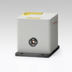
应用立陶宛Ekspla公司SL-334型高能量亚纳秒(150皮秒)脉冲Nd:YAG激光器输出的1064, 532,266nm 单脉冲能量500,240, 和 80 mJ激光脉冲以及5倍频213nm 输出四种波长合束位一束实现单发四色Z-箍缩过程等离子体诊断。
方案详情

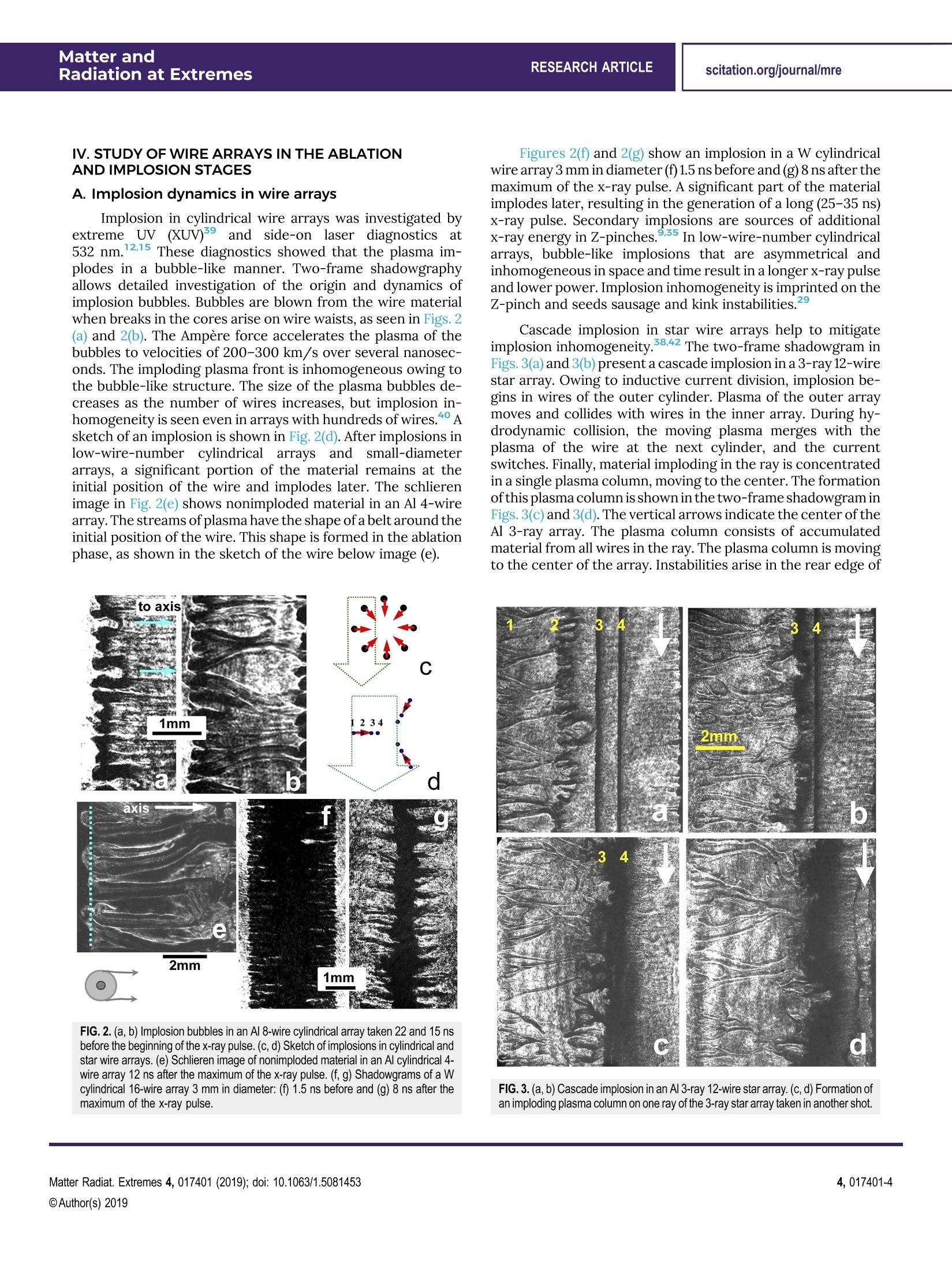
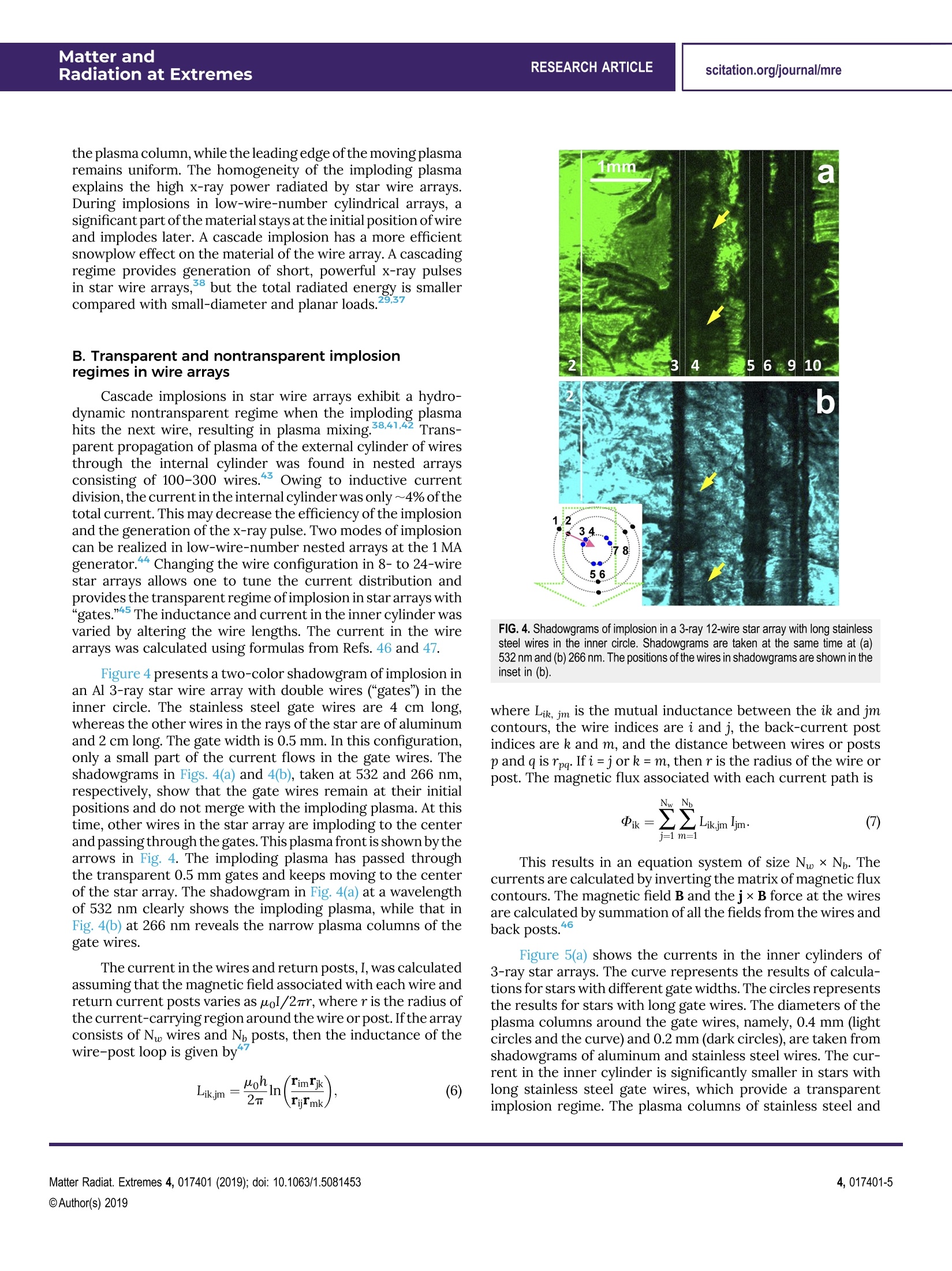
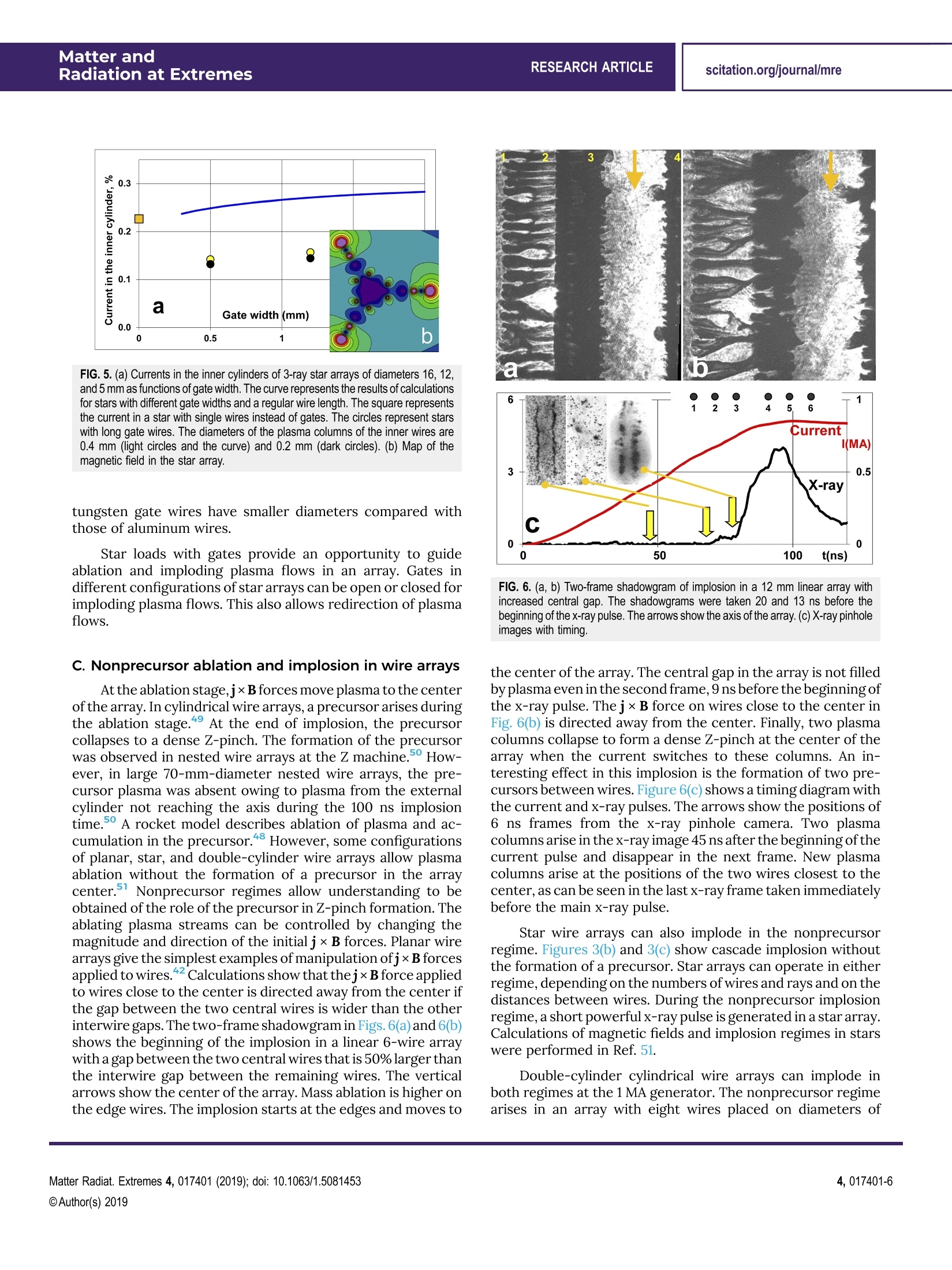
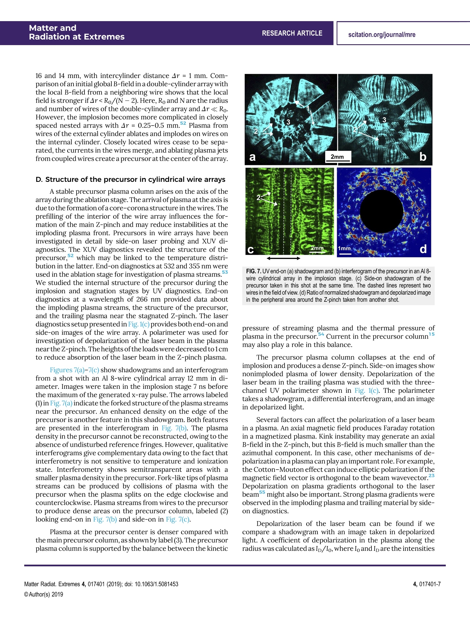
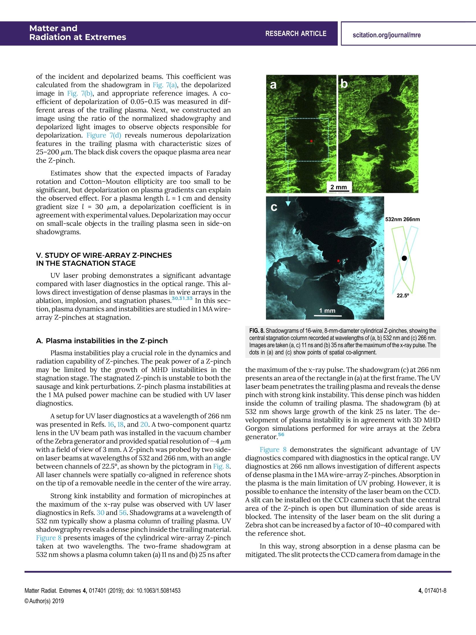
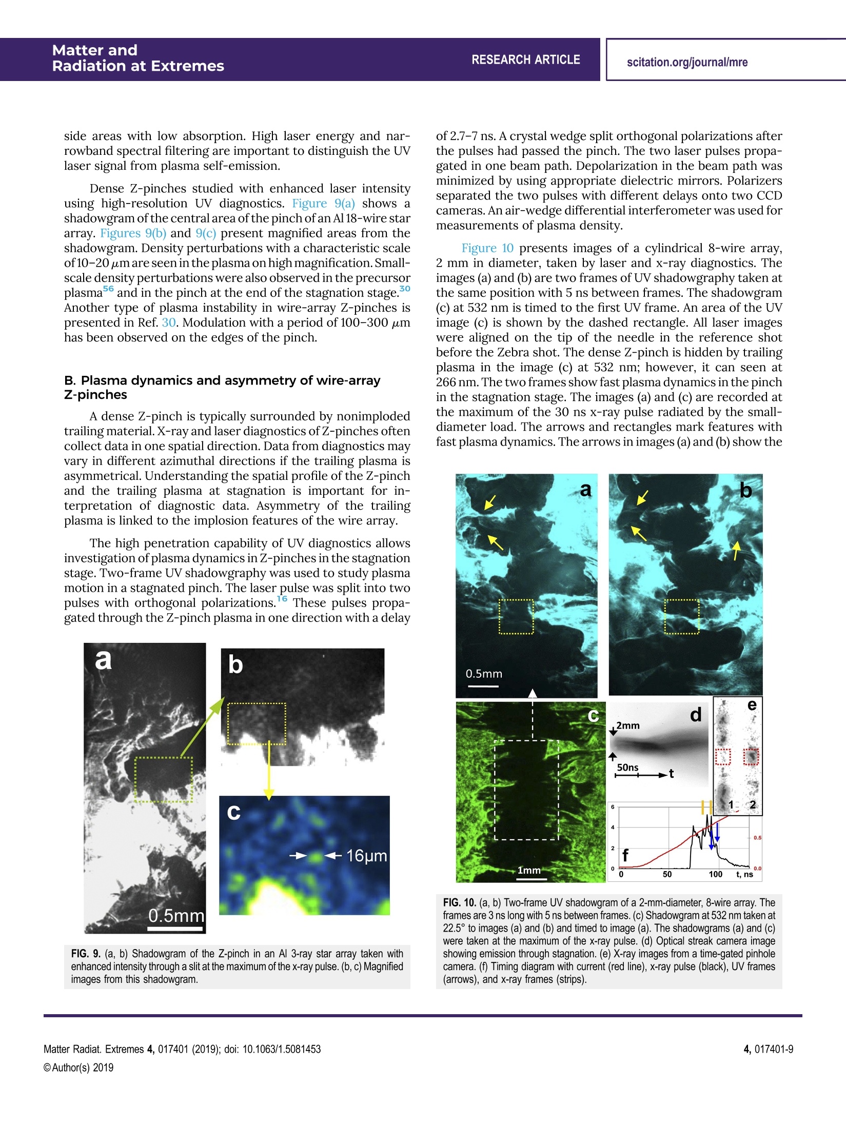
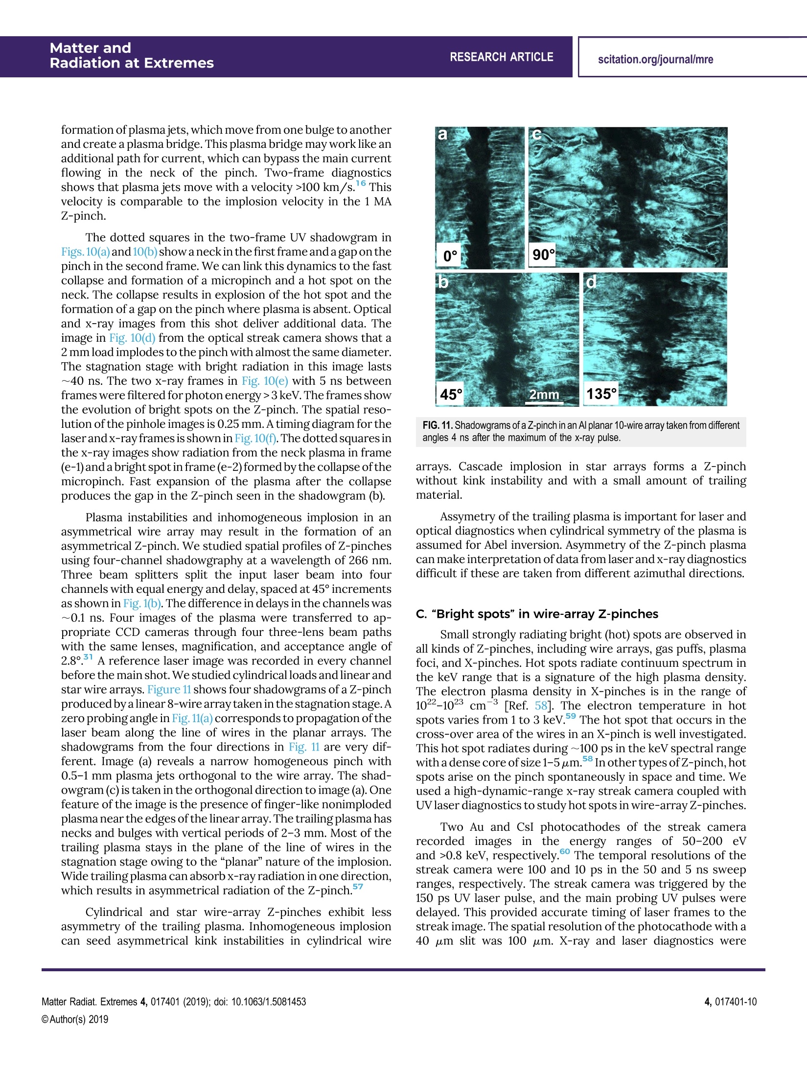
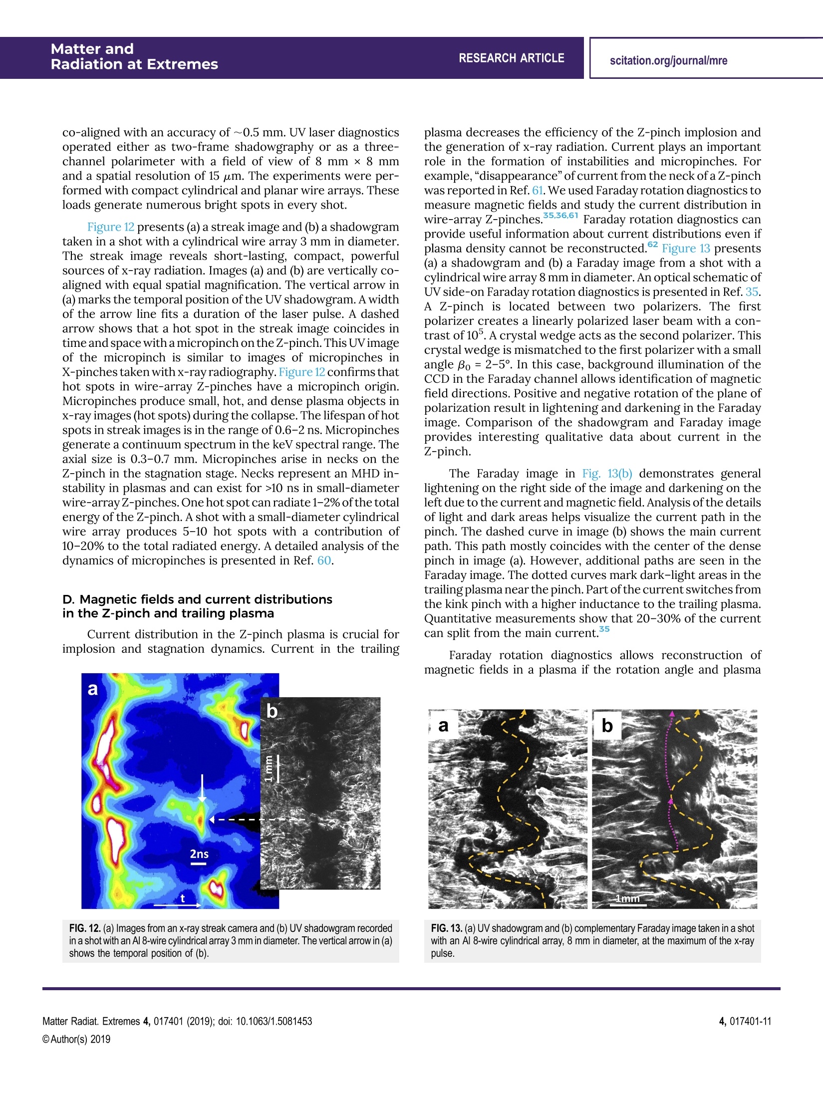
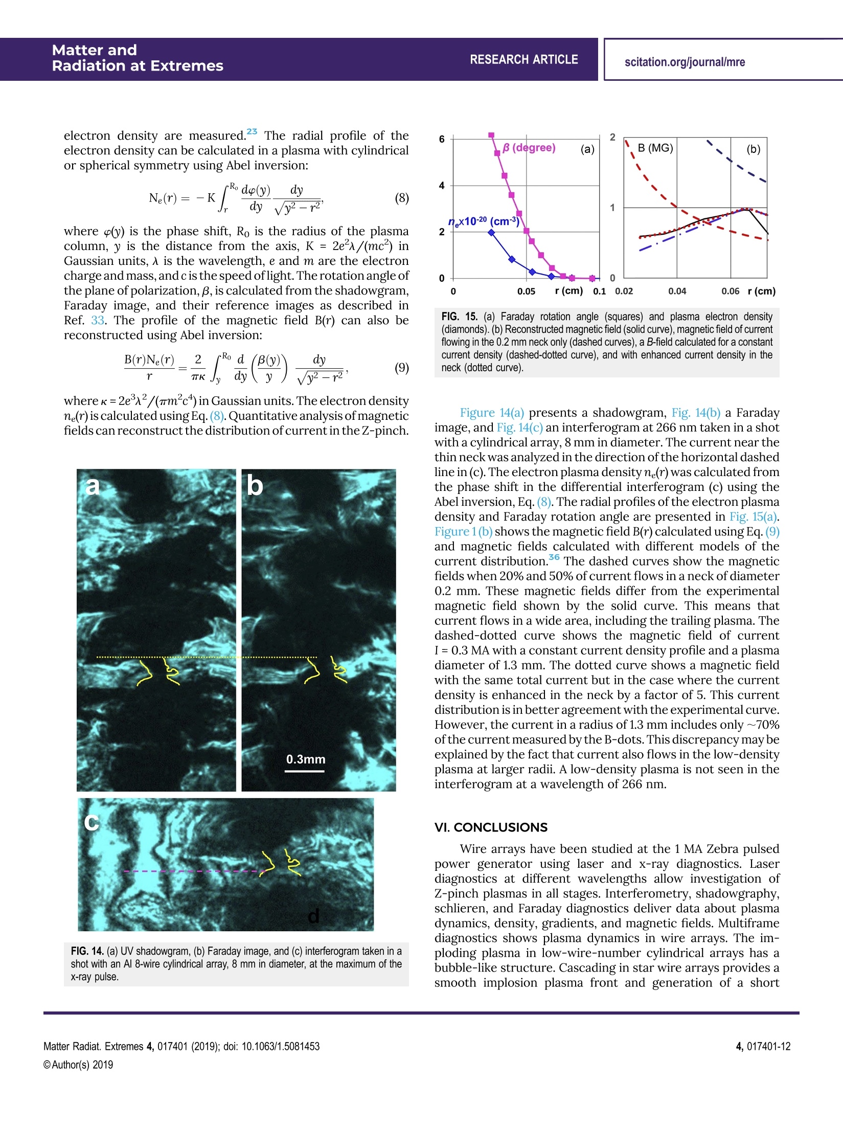
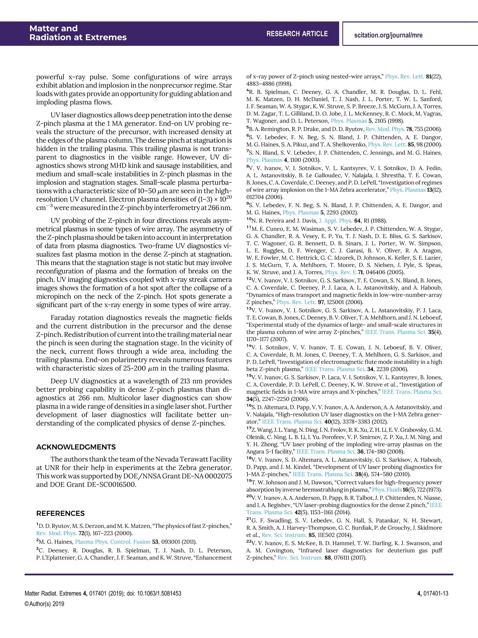
Matter andRadiation at ExtremesRESEARCH ARTICLE scitation.org/journal/mreExport Citation Investigation of wire-array Z-pinches bylaser probing diagnosticsEP Cite as: Matter Radiat. Extremes 4, 017401 (2019); https://doi.org/10.1063/1.5081453Submitted: 14 November 2018 . Accepted: 15 November 2018.Published Online: 17 January 2019 V. V. Ivanov,A. A. Anderson, and D. Papp COLLECTIONS EP This paper was selected as an Editor’s Pick coponaccess View Online Investigation of wire-array Z-pinches by laserprobing diagnostics Cite as: Matter Radiat. Extremes 4, 017401 (2019); doi: 10.1063/1.5081453 Submitted: 14 November2018·Accepted:15 November 2018· View Online CrossMark Published Online: 17 January 2019 V. V. Ivanov, A. A. Anderson, and D. Papp AFFILIATIONS Department of Physics, University of Nevada, Reno,Nevada 89557, USA ‘ELI-ALPS, ELI-HU Nkft.,H-6720 Szeged, Hungary ABSTRACT Laser diagnostics provides powerful tools for the investigation of dense Z-pinches. In this paper, wire-array Z-pinches are in-vestigated at the 1 MA Zebra generator using laser diagnostics at different wavelengths coupled with x-ray diagnostics. Plasmadynamics during the ablation, implosion, and stagnation stages are observed by multiframe diagnostics. Cascading and non-precursor implosions are studied in wire arrays. Ultraviolet diagnostics allows deep penetration into the Z-pinch plasma atstagnation. End-on probing reveals the complicated structure of the precursor. Strong magnetohydrodynamic instabilities arefound in a dense pinch hidden in the trailing plasma. Small-scale instabilities are seen in the Z-pinch plasma with micrometerresolution. Probing of the pinch from four directions shows asymmetrical trailing plasma in some configurations of wire arrays.Faraday rotation diagnostics reveals the magnetic fields and the current distribution in the plasma of the precursor and Z-pinch.Redistribution of current in the trailing plasma is seen during kink and sausage instabilities in the stagnation stage. The formation ofmicropinches and hot spots in the Z-pinch is analyzed with coupled laser and x-ray diagnostics. Different laser diagnostics allow thestudy of Z-pinch plasmas in all stages, including fast dynamics and instabilities. C 2019 Author(s). All article content, except where otherwise noted, is licensed under a Creative Commons Attribution (CC BY) license(http://creativecommons.org/licenses/by/4.0/). https://doi.org/10.1063/1.5081453 I. INTRODUCTION Z-pinches are efficient laboratory sources of powerfulx-ray radiation. They can be applied in a number of areas ofhigh-energy-density laboratory plasma physics, includinglaboratory astrophysics, atomic and radiation physics andspectroscopy, studies of material properties, and fusionresearch. Although there has been impressive experi-mental progress in Z-pinch physics and its applications atcurrents of 10-20 MA, many aspects of the physics of denseZ-pinches can be studied at load currents in the range1-2 MA. Laser probing diagnostics has been widely used for in-vestigation of Z-pinch plasmas and to clarify the physicalprocesses involved in Z-pinches. The main stages involved inwire-array Z-pinch and plasma instabilities were elucidated inthe first decade of this century. The formation of a core-corona structure on wires after flashover and the generationof aperiodic plasma jets in the ablation stage was investigated inRef. 6. Ablation plasma streams reach the center of acylindricalwire array and form a precursor plasma column. During the implosion stage, the plasma of acylindrical wire array implodesin a snowplow manner and produces a dense Z-pinch. End-onand side-on probing at a wavelength of 532 nm was applied tostudy the ablation and implosion stages.The Z-pinch radiates ashort powerful x-ray burst during the stagnation stage. TheZ-pinch plasma column is highly inhomogeneous owing to thedevelopment of strong magnetohydrodynamic (MHD) kink andsausage instabilities. Bright, powerful, and compact x-raysources termed micropinches or“hot spots" arise in differenttypes of Z-pinch.All of the abovementioned features of wirearray Z-pinches have been observed in different machines atload currents from 1 to 10 MA. The application of multiframe laser diagnostics toZ-pinches has revealed the implosion dynamics in wire arrays.The formation and dynamics of plasma bubbles at thebeginning of the implosion stage in cylindrical wire arrayshave been studied with side-on probing at 532 nm..12|2Precursor plasma columns in wire arrays have been found tocontain fine structures with large- and small-scale in-stabilities.3Cascadingof the characteristic size of instabilities to smaller scales has been linked to flute-modeturbulence in the precursor plasma.Faraday rotationdiagnostics has allowed the investigation of magnetic fieldsand reconstruction of the current distribution in wire arrays.Currents of 0.1-0.2 MA have been measured in the precursorplasma column in the ablation stage.15 Bubble-like areas withperturbations of the magnetic field have been observed inFaraday images of the precursor plasma. The main features ofthe formation and evolution of the dense pinch and trailingmass have been studied with laser diagnostics at a wavelengthof 532 nm. Shadowgraphy, interferometry, schlieren, and Faradayrotation diagnostics have provided data about Z-pinch plasmaswith electron densities of the order of 101cm-3.However,laserdiagnostics in the optical range cannot be applied to thestagnation phase of Z-pinches owing to strong absorption andrefraction ofthe laser beam in the dense plasma.Alaser beam ofwavelength 532 nm cannot pass through the trailing plasma andprobe the Z-pinch. However, ultraviolet (UV) laser diagnosticshas shown promise for the investigation of dense Z-pinchplasmas.16-18 In this paper, we describe the investigation of wire-arrayZ-pinches at the Nevada Terawatt Facility (NTF) at the Uni-versity of Nevada, Reno (UNR). Laser diagnostics at wavelengthsfrom 213 to 1064 nm have been applied to wire arrays at differentphases. Different configurations of wire arrays are studied,including star, linear (planar), and double-cylinder loads. UVhigh-resolution diagnostics is deployed at the 1 MA Zebragenerator and allows detailed investigation of the stagnationstage in a dense Z-pinch. Laser probing includes side-on andend-on shadowgraphy, interferometry,and Faraday rotationdiagnostics. Shadowgraphy with a spatial resolution of <5 umshows microperturbations of the plasma density in the pre-cursor and Z-pinch. Two-frame diagnostics reveals fast plasmamotion in the Z-pinch in the stagnation phase. The structure ofthe magnetic fields is revealed and the redistribution of currentin the trailing plasma and Z-pinch is reconstructed usingFaraday diagnostics. UV diagnostics reveals the origin of “hotspots”in Z-pinches. Laser probing in four directions revealsstrong asymmetry of some wire-array Z-pinches. The dynamicsof implosion and stagnation and the development of instabilitiesin Z-pinches are in agreement with three-dimensional MHDsimulations. II. LASER DIAGNOSTICS FOR Z-PINCH PLASMAS Laser diagnostics must be optimized for the plasma objectof interest. The propagation of a probe beam in a plasma de-pends on the laser wavelength. Different diagnostics may havespecific goals and fields of application. Shadowgraphy, in-terferometry, schlieren, and Faraday rotation diagnostics arethe most common imaging diagnostics for plasmas. They deliverinformation on density, dynamics, gradients, and magneticfields in a plasma. The phase shift, absorption, scattering ongradients, and rotation of the plane of polarization of the laserbeam in a plasma depend on the wavelength of the radiation. The formulas presented below define these parameters in aplasma. The critical plasma density ne defines an electron densitythreshold for propagation of laser radiation in a plasma: with 入 measured in cm and n in cm3. The critical densitync=4×1021cm-3at532 nm,andn=1.6×10²²cmat the fourthharmonic of the neodymium laser (266 nm). For example, alaser-produced plasma can be at the critical density for heatingby infrared (IR) light, but transparent to UV probing. Theelectron plasma density in MA-level Z-pinches is less thancritical. In this case, absorption and refraction in the plasma areimportant for diagnostics. The increment of inverse brems-strahlung absorption is proportional to 2 [Refs. 19 and 20]: where入 is the laser beam wavelength in cm, ne is the electronplasma density in cm-3, Te is the electron temperature in eV,A=23-1n(nZ.Te3/2) is the Coulomb logarithm, Z is theionic charge, and ne is the critical density. The total absorptiondepends exponentially on the increment and the plasma size.The advantage ofUV radiation is most pronounced in a plasmawithhigh absorption. At ahigh plasma density, the IR and opticalranges cannot be used, but transmission in the UV range maystill be acceptable. UV diagnostics shows a significant advan-tage in dense plasma over diagnostics in the IR and visibleranges. However, a plasma object with a low density is trans-. parent to UV radiation. Diagnostics in the IR and optical rangesl are preferable for plasmas with electron density <1019 cm3[Refs. 2 and 22]. Interferometry allows reconstruction of the electronplasma density from the phase shift of a laser beam in a plasmaThe phase shift is calculated from the shift of fringes in theinterferogram using the formula23.24 where a is measured in fringes,入 is in cm, and the plasma lengthL is in cm. Abel inversion is used for reconstruction of the radialelectron density in plasma objects with spherical or cylindricasymmetry. The angle of refraction on the plasma gradient, @, can becalculated using the formula2324 where the refraction angle is in radians and other quantities arein cm. The refraction angle is proportional to A" and so issmaller by a factor of 16 at a wavelength of 266 nm comparedwith 1064 nm. Refraction of rays is responsible for the efficiencyof schlieren diagnostics. A schlieren effect can be seen irshadowgrams if the acceptance angle of the laser beam path issmaller than the refraction angle. Faraday rotation of the plane of polarization of the laserbeam depends on the magnetic field in the plasma. The angle ofrotation of the plane of polarization, B, is given by23.25 where the rotation angle is in radians, the wavelength入 is in cm,the length L of the plasma slab is in cm, and the electron densityneis in cm. B, in gauss, is the projection of the magnetic fieldonto the direction ofthe laser beam. The angle of rotation of theplane of polarization is proportional to A, which allows one tomeasure stronger magnetic fields in the Z-pinch in the UVrange. IR Faraday rotation diagnostics are sensitive to magneticfields in a low-density plasma, but refraction on plasmagradients should be taken into account.21 Equations (1)-(5) help to determine optimal wavelengthsand diagnostic types, depending on the density, gradient, andsize of the plasma object. UV laser probing allows deeperpenetration in dense plasmas. UV diagnostics allows in-vestigation of1MAZ-pinches even in the stagnation stage. Theshort wavelength of UV radiation can also provide higherspatial resolution of laser diagnostics owing to the smallerdiffraction limit. Laser diagnostics in the IR and optical rangesare more effective for investigation of plasmas of lowerdensity. III. LASER DIAGNOSTICS AT THE ZEBRA GENERATOR Z-pinch experiments were performed at the Zebra pulsedpower generator.26 The 1 MA current pulse of the generatorhas a rising edge of 80 ns (10-90%), with a current prepulse of200 ns. The impedance of the transmission line is 1.9 2. Aregime with enhanced load current of 1.5-1.7 MA is availablewith the use of a load current multiplier.28 The configuration ofthe anode-cathode area is shown in Fig. 1(a). Current is mea-sured by three B-dot sensors placed on the anode plate and onesensor located in the stack before the load. The configuration ofthe anode-cathode area allows installation of apparatus in thevacuum chamber. Optics and apparatus are mounted ondamping platforms owing to the strong after-shot shock>200g. Laser diagnostics can use 5 and 7.5 cm windows spaced at22.5° increments in the vacuum chamber as shownin Fig.1(b). Thesolid arrows in Fig.1(b) show channels for regular side-on di-agnostics, including five-frame shadowgraphy, interferometry,schlieren, and Faraday rotation diagnostics. Details of di-agnostics in different experiments are presented in Refs. 15, 29,and30. The dotted arrows in Fig. 1(b)show probingofthe Z-pinchin four directions with 45° shifts.Figure 1(c) shows an end-onlaser polarimeter. Alaser beam polarized by a polarizer (P) passesvertically through the wire array. A mirror(M) in the hollowcathode reflects the beam to the window in the chamber. Acrystal wedge (W) acts as the second polarizer of the polarimeterand splits two orthogonal polarizations. Mach-Zehnder and shearing air-wedge interferometers’are used for plasma density measurements. A differentialinterferometer is less sensitive by a factor of 5-10 compared FIG. 1.(a) Configuration of the load zone in the vacuum chamber. (b) Directions ofside-onlaser probing on the chamber. Solid arrows show regular probing directions,and dotted arrows show probing directions for investigation of pinch asymmetry.(C)End-on laser probing in the vacuum chamber. with a Mach-Zehnder interferometer. This allows measure-ments of higher electron density, especially in the UVrange.33 A commercial Nd:YAG laser (EKSPLA SL-334) is used forplasma diagnostics. The laser generates pulses of duration of150 ps at wavelengths 1064, 532, and 266 nm and energies 500240, and 80 mJ. A fifth harmonic at 213 nm was generated with an additional β-barium borate (BBO) crystal. Four laser harmonicspropagating in one beam path can be used for four-color plasmadiagnostics in a single shot. Three-channel Faraday rotation diagnostics at wave-lengths of 532 and 266 nm are used at the Zebra chamber formeasurements offmagnetic fields.15,20 Thecurrentdistribution in the precursor and trailing plasma near theZ-pinch can be reconstructed from the magnetic fieldprofile35.36 The spatial resolution of regular laser diagnostics at theZebra generator is 12-25 um, depending on the installedconfiguration and the magnification of the beam path. A UVlaser channel with resolution 4 um is used for investigation ofsmall-scale perturbations in the Z-pinch. Theconfigurationsof the channels and diagnostics are varied according to thegoals of specific experiments. Z-pinches were produced by implosion of cylindricalplanar,and star388wire arrays 2 cm tall. Arrays typicallyconsisted of 8-32 wires. Various wire materials such as Al and Auwere tested in different shots. A. Implosion dynamics in wire arrays Implosion in cylindrical wire arrays was investigated byextreme UV (XUV)39and side-on laser diagnostics at532 nm. 2.15 These diagnostics showed that the plasma im-plodes in a bubble-like manner. Two-frame shadowgraphyallows detailed investigation of the origin and dynamics ofimplosion bubbles. Bubbles are blown from the wire materialwhen breaks in the cores arise on wire waists, as seen in Figs.2(a)and 2(b). The Ampere force accelerates the plasma of thebubbles to velocities of 200-300 km/s over several nanosec-onds. The imploding plasma front is inhomogeneous owing tothe bubble-like structure. The size of the plasma bubbles de-creases as the number of wires increases, but implosion in-homogeneity is seen even in arrays with hundreds of wires. Asketch of an implosion is shown in Fig.2(d). After implosions inlow-wire-number cylindrical arrays and small-diameterarrays, a significant portion of the material remains at theinitial position of the wire and implodes later. The schlierenimage in Fig. 2(e) shows nonimploded material in an Al 4-wirearray. The streams of plasma have the shape of a belt around theinitial position of the wire. This shape is formed in the ablationphase, as shown in the sketch of the wire below image (e). 1 234 d FIG. 2.(a, b) Implosion bubbles in an Al 8-wire cylindrical array taken 22 and 15 nsbefore the beginning of the x-ray pulse. (c, d) Sketch of implosions in cylindrical andstar wire arrays.(e) Schlieren image of nonimploded material in an Al cylindrical 4-wire array 12 ns after the maximum of the x-ray pulse. (f, g) Shadowgrams of a Wcylindrical 16-wire array 3 mm in diameter: (f) 1.5 ns before and (g)8 ns after themaximum of the x-ray pulse. Figures 2(f) and 2(g) show an implosion in a W cylindricalwire array 3 mm in diameter (f)1.5 ns before and (g) 8 ns after themaximum of the x-ray pulse. A significant part of the materialimplodes later, resulting in the generation of a long (25-35 ns)x-ray pulse. Secondary implosions are sources of additionalx-ray energy in Z-pinches.9,35 In low-wire-number cylindricalarrays, bubble-like implosions that are asymmetrical andinhomogeneous in space and time result in a longer x-ray pulseand lower power. Implosion inhomogeneity is imprinted on theZ-pinch and seeds sausage and kink instabilities. Cascade implosion in star wire arrays help to mitigateimplosion inhomogeneity.38.42 The two-frame shadowgram inFigs. 3(a)and 3(b) present a cascade implosion in a 3-ray 12-wirestar array. Owing to inductive current division, implosion be-gins in wires of the outer cylinder. Plasma of the outer arraymoves and collides with wires in the inner array. During hy-drodynamic collision, the moving plasma merges with theplasma of the wire at the next cylinder, and the currentswitches. Finally, material imploding in the ray is concentratedin a single plasma column, moving to the center. The formationofthis plasma column is shown in the two-frame shadowgram inFigs. 3(c) and 3(d). The vertical arrows indicate the center of theAl 3-ray array. The plasma column consists of accumulatedmaterial from all wires in the ray. The plasma column is movingto the center of the array. Instabilities arise in the rear edge of FIG.3. (a,b) Cascade implosion in an Al 3-ray 12-wire star array. (c, d) Formation ofan imploding plasma column on one ray of the 3-ray star array taken in another shot. the plasma column, while the leading edge of the moving plasmaremains uniform. The homogeneity of the imploding plasmaexplains the high x-ray power radiated by star wire arrays.During implosions in low-wire-number cylindrical arrays, asignificant part of the material stays at the initial position ofwireand implodes later. A cascade implosion has a more efficientsnowplow effect on the material of the wire array. A cascadingregime provides generation of short, powerful x-ray pulsesin star wire arrays, but the total radiated energy is smallercompared with small-diameter and planar loads.29.37 B. Transparent and nontransparent implosionregimes in wire arrays Cascade implosions in star wire arrays exhibit a hydro-dynamic nontransparent regime when the implodin84g plasmahits the next wire, resulting in plasma mixing.38.41.42Trans-parent propagation of plasma of the external cylinder of wiresthrough the internal cylinder was found in nested arraysconsisting of 100-300 wires.3Owing to inductive currentdivision, the current in the internal cylinder was only~4% ofthetotal current. This may decrease the efficiency of the implosionand the generation of the x-ray pulse. Two modes of implosioncan be realized in low-wire-number nested arrays at the 1 MAgenerator. Changing the wire configuration in 8- to 24-wirestar arrays allows one to tune the current distribution andprovides the transparent regime of implosion in star arrays with"gates."5 The inductance and current in the inner cylinder wasvaried by altering the wire lengths. The current in the wirearrays was calculated using formulas from Refs. 46 and 47. Figure 4 presents a two-color shadowgram of implosion inan Al 3-ray star wire array with double wires (“gates") in theinner circle. The stainless steel gate wires are 4 cm long,whereas the other wires in the rays of the star are of aluminumand 2 cm long. The gate width is 0.5 mm. In this configuration,only a small part of the current flows in the gate wires. Theshadowgrams in Figs. 4(a)and 4(b), taken at 532 and 266 nm,respectively, show that the gate wires remain at their initialpositions and do not merge with the imploding plasma. At thistime, other wires in the star array are imploding to the centerand passing through the gates. This plasma front is shown by thearrows in Fig. 4. The imploding plasma has passed throughthe transparent 0.5 mm gates and keeps moving to the centerof the star array. The shadowgram in Fig. 4(a) at a wavelengthof 532 nm clearly shows the imploding plasma, while that inFig.4(b) at 266 nm reveals the narrow plasma columns of thegate wires. The current in the wires and return posts, I, was calculatedassuming that the magnetic field associated with each wire andreturn current posts varies as uoI/2mr, where r is the radius ofthe current-carrying region around the wire or post. fthe arrayconsists of Nu wires and N posts, then the inductance of thewire-post loop is given by".47 FIG. 4. Shadowgrams of implosion in a 3-ray 12-wire star array with long stainlesssteel wires in the inner circle. Shadowgrams are taken at the same time at (a)\/532 nm and(b)266 nm. The positions of the wires in shadowgrams are shown in theinset in (b). where Lik, jm is the mutual inductance between the ik and jmcontours, the wire indices are i and j, the back-current postindices are k and m, and the distance between wires or postsp and q is rpq. Ifi=jork=m, then r is the radius of the wire orpost. The magnetic flux associated with each current path is This results in an equation system of size Nu × N. Thecurrents are calculated by inverting the matrix of magnetic fluxcontours. The magnetic field B and the j×B force at the wiresare calculated by summation of all the fields from the wires andback posts.46 Figure 5(a) shows the currents in the inner cylinders of3-ray star arrays. The curve represents the results of calcula-tions for stars with different gate widths. The circles representsthe results for stars with long gate wires. The diameters of theplasma columns around the gate wires, namely, 0.4 mm (lightcircles and the curve) and 0.2 mm (dark circles), are taken fromshadowgrams of aluminum and stainless steel wires. The cur-rent in the inner cylinder is significantly smaller in stars withlong stainless steel gate wires, which provide a transparentimplosion regime. The plasma columns of stainless steel and FIG. 5.(a) Currents in the inner cylinders of 3-ray star arrays of diameters 16, 12,and 5 mm as functions of gate width. The curve represents the results of calculationsfor stars with different gate widths and a regular wire length. The square representsthe current in a star with single wires instead of gates. The circles represent starswith long gate wires. The diameters of the plasma columns of the inner wires are0.4 mm (light circles and the curve) and 0.2 mm (dark circles). (b) Map of themagnetic field in the star array. tungsten gate wires have smaller diameters compared withthose of aluminum wires. Star loads with gates provide an opportunity to guideablation and imploding plasma flows in an array. Gates indifferent configurations of star arrays can be open or closed forimploding plasma flows. This also allows redirection of plasmaflows. C. Nonprecursor ablation and implosion in wire arrays At the ablation stage,jxB forces move plasma to the centerof the array. In cylindrical wire arrays, a precursor arises duringthe ablation stage. At the end of implosion, the precursorcollapses to a dense Z-pinch. The formation of the precursorwas observed in nested wire arrays at the Z machine. How-ever, in large 70-mm-diameter nested wire arrays, the pre-cursor plasma was absent owing to plasma from the externalcylinder not reaching the axis during the 100 ns implosiontime. A rocket model describes ablation of plasma and ac-cumulation in the precursor.+8 However,some configurationsof planar, star, and double-cylinder wire arrays allow plasmaablation without the formation of a precursor in the arraycenter.Nonprecursor regimes allow understanding to beobtained of the role of the precursor in Z-pinch formation. Theablating plasma streams can be controlled by changing themagnitude and direction of the initial j×B forces. Planar wirearrays give the simplest examples of manipulation ofjxB forcesapplied to wires.Calculations show that thej×B force appliedto wires close to the center is directed away from the center ifthe gap between the two central wires is wider than the otherinterwire gaps. The two-frame shadowgram in Figs. 6(a)and 6(b)shows the beginning of the implosion in a linear 6-wire arraywith a gap between the two central wires that is 50%larger thanthe interwire gap between the remaining wires. The verticalarrows show the center of the array. Mass ablation is higher onthe edge wires. The implosion starts at the edges and moves to FIG. 6. (a, b) Two-frame shadowgram of implosion in a 12 mm linear array withincreased central gap. The shadowgrams were taken 20 and 13 ns before thebeginning of the x-ray pulse. The arrows show the axis of the array.(C) X-ray pinholeimages with timing. the center of the array. The central gap in the array is not filledby plasma even in the second frame, 9 ns before the beginning ofthe x-ray pulse. The j× B force on wires close to the center inFig. 6(b) is directed away from the center. Finally, two plasmacolumns collapse to form a dense Z-pinch at the center of thearray when the current switches to these columns. An in-teresting effect in this implosion is the formation of two pre-cursors between wires. Figure 6(C) shows a timing diagram withthe current and x-ray pulses. The arrows show the positions of6 ns frames from the x-ray pinhole camera. Two plasmacolumns arise in the x-ray image 45 ns after the beginning of thecurrent pulse and disappear in the next frame. New plasmacolumns arise at the positions of the two wires closest to thecenter, as can be seen in the last x-ray frame taken immediatelybefore the main x-ray pulse. Star wire arrays can also implode in the nonprecursorregime. Figures 3(b) and 3(c) show cascade implosion withoutthe formation of a precursor. Star arrays can operate in eitherregime, depending on the numbers of wires and rays and on thedistances between wires. During the nonprecursor implosionregime, a short powerful x-ray pulse is generated in a star array.Calculations of magnetic fields and implosion regimes in starswere performed in Ref. 51. Double-cylinder cylindrical wire arrays can implode inboth regimes at the 1 MA generator. The nonprecursor regimearises in an array with eight wires placed on diameters of 16 and 14 mm, with intercylinder distance Ar =1 mm. Com-parison of an initial global B-field in a double-cylinder array withthe local B-field from a neighboring wire shows that the localfield is stronger ifAr100 km/s.Thisvelocity is comparable to the implosion velocity in the 1 MAZ-pinch. The dotted squares in the two-frame UV shadowgram inFigs.10(a)and10(b)show a neck in the first frame and agap on thepinch in the second frame. We can link this dynamics to the fastcollapse and formation of a micropinch and a hot spot on theneck. The collapse results in explosion of the hot spot and theformation of a gap on the pinch where plasma is absent. Opticaland x-ray images from this shot deliver additional data. Theimage in Fig.10(d) from the optical streak camera shows that a2 mmload implodes to the pinch with almost the same diameter.The stagnation stage with bright radiation in this image lasts~40 ns. The two x-ray frames in Fig. 10(e) with 5 ns betweenframes were filtered for photon energy>3 keV. The frames showthe evolution of bright spots on the Z-pinch. The spatial reso-lution of the pinhole images is 0.25 mm. A timing diagram for thelaser andx-ray frames is shown in Fig.10(f). The dotted squares inthe x-ray images show radiation from the neck plasma in frame(e-1)and a bright spot in frame (e-2) formed by the collapse ofthemicropinch. Fast expansion of the plasma after the collapseproduces the gap in the Z-pinch seen in the shadowgram (b). Plasma instabilities and inhomogeneous implosion in anasymmetrical wire array may result in the formation of anasymmetrical Z-pinch. We studied spatial profiles of Z-pinchesusing four-channel shadowgraphy at a wavelength of 266 nm.Three beam splitters split the input laser beam into fourchannels with equal energy and delay, spaced at 45° incrementsas shown in Fig.1(b). The difference in delays in the channels was~0.1 ns. Four images of the plasma were transferred to ap-propriate CCD cameras through four three-lens beam pathswith the same lenses, magnification, and acceptance angle of2.8 A reference laser image was recorded in every channelbefore the main shot. We studied cylindrical loads and linear andstar wire arrays. Figure 11 shows four shadowgrams of a Z-pinchproduced by a linear 8-wire array taken in the stagnation stage. Azero probing angle in Fig. 11(a) corresponds to propagation of thelaser beam along the line of wires in the planar arrays. Theshadowgrams from the four directions in Fig. 11 are very dif-ferent. Image (a) reveals a narrow homogeneous pinch with0.5-1 mm plasma jets orthogonal to the wire array. The shad-owgram (c) is taken in the orthogonal direction to image (a). Onefeature of the image is the presence of finger-like nonimplodedplasma near the edges of the linear array. The trailing plasma hasnecks and bulges with vertical periods of 2-3 mm. Most of thetrailing plasma stays in the plane of the line of wires in thestagnation stage owing to the “planar"nature of the implosion.Wide trailing plasma can absorb x-ray radiation in one direction,which results in asymmetrical radiation of the Z-pinch. Cylindrical and star wire-array Z-pinches exhibit lessasymmetry of the trailing plasma. Inhomogeneous implosioncan seed asymmetrical kink instabilities in cylindrical wire FIG. 11. Shadowgrams of a Z-pinch in an Al planar 10-wire array taken from differentangles 4 ns after the maximum of the x-ray pulse. arrays. Cascade implosion in star arrays forms a Z-pinchwithout kink instability and with a small amount of trailingmaterial. Assymetry of the trailing plasma is important for laser andoptical diagnostics when cylindrical symmetry of the plasma isassumed for Abel inversion. Asymmetry of the Z-pinch plasma. can make interpretation of data from laser and x-ray diagnosticsdifficult if these are taken from different azimuthal directions. C. “Bright spots" in wire-array Z-pinches Small strongly radiating bright (hot) spots are observed inall kinds of Z-pinches, including wire arrays, gas puffs, plasmafoci, and X-pinches. Hot spots radiate continuum spectrum inthe keV range that is a signature of the high plasma densityThe electron plasma density in X-pinches is in the range of1022-1023 cm [Ref. 58]. The electron temperature in hotspots varies from 1 to 3 keV.5 The hot spot that occurs in thecross-over area of the wires in an X-pinch is well investigated.This hot spot radiates during ~100 ps in the keV spectral rangewith a dense core of size 1-5 um.In other types of Z-pinch, hotspots arise on the pinch spontaneously in space and time. Weused a high-dynamic-range x-ray streak camera coupled withUVlaser diagnostics to study hot spots in wire-array Z-pinches Two Au and CsI photocathodes of the streak camerarecorded images in the energy ranges of 50-200eVand >0.8 keV, respectively.The temporal resolutions of thestreak camera were 100 and 10 ps in the 50 and 5 ns sweepranges, respectively. The streak camera was triggered by the150 ps UV laser pulse, and the main probing UV pulses weredelayed. This provided accurate timing of laser frames to thestreak image. The spatial resolution of the photocathode with a40 um slit was 100 um. X-ray and laser diagnostics were co-aligned with an accuracy of ~0.5 mm. UV laser diagnosticsoperated either as two-frame shadowgraphy or as a three-channel polarimeter with a field of view of 8 mm× 8 mmand a spatial resolution of 15 um. The experiments were per-formed with compact cylindrical and planar wire arrays. Theseloads generate numerous bright spots in every shot. Figure 12 presents (a) a streak image and (b) a shadowgramtaken in a shot with a cylindrical wire array 3 mm in diameter.The streak image reveals short-lasting, compact, powerfulsources of x-ray radiation. Images (a) and (b) are vertically co-aligned with equal spatial magnification. The vertical arrow in(a)marks the temporal position of the UV shadowgram. A widthof the arrow line fits a duration of the laser pulse. A dashedarrow shows that a hot spot in the streak image coincides intime and space with a micropinch on theZ-pinch.This UV imageof the micropinch is similar to images of micropinches inX-pinches taken with x-ray radiography. Figure 12 confirms thathot spots in wire-array Z-pinches have a micropinch origin.Micropinches produce small, hot, and dense plasma objects inx-ray images (hot spots) during the collapse. The lifespan of hotspots in streak images is in the range of 0.6-2 ns. Micropinchesgenerate a continuum spectrum in the keV spectral range. Theaxial size is 0.3-0.7 mm. Micropinches arise in necks on theZ-pinch in the stagnation stage.Necks represent an MHD in-stability in plasmas and can exist for >10 ns in small-diameterwire-arrayZ-pinches. One hot spot can radiate 1-2% of the totalenergy of the Z-pinch. A shot with a small-diameter cylindricalwire array produces 5-10 hot spots with a contribution of10-20% to the total radiated energy. A detailed analysis of thedynamics of micropinches is presented in Ref. 60. D. Magnetic fields and current distributionsin the Z-pinch and trailing plasma Current distribution in the Z-pinch plasma is crucial forimplosion and stagnation dynamics. Current in the trailing FIG. 12.(a) Images from an x-ray streak camera and (b) UV shadowgram recordedin a shot with an Al 8-wire cylindrical array 3 mm in diameter. The vertical arrow in (a)shows the temporal position of (b). plasma decreases the efficiency of the Z-pinch implosion andthe generation of x-ray radiation. Current plays an importantrole in the formation of instabilities and micropinches. Forexample,"disappearance”of current from the neck of a Z-pinchwas reported in Ref. 61. We used Faraday rotation diagnostics tomeasure magnetic fields and study the current distribution inwire-array Z-pinches.35.36.61 Faraday rotation diagnostics canprovide useful information about current distributions even ifplasma density cannot be reconstructed.2 Figure 13 presents(a) a shadowgram and (b) a Faraday image from a shot with acylindrical wire array 8 mm in diameter. An optical schematic ofUV side-on Faraday rotation diagnostics is presented in Ref. 35.A Z-pinch is located between two polarizers. The firstpolarizer creates a linearly polarized laser beam with a con-trast of 10. A crysta wedge acts as the second polarizer. Thiscrystal wedge is mismatched to the first polarizer with a smallangle Bo =2-5°. In this case, background illumination of theCCD in the Faraday channel allows identification of magneticfield directions. Positive and negative rotation of the plane ofpolarization result in lightening and darkening in the Faradayimage. Comparison of the shadowgram and Faraday imageprovides interesting qualitative data about current in theZ-pinch. The Faraday image in Fig. 13(b) demonstrates generallightening on the right side of the image and darkening on theleft due to the current and magnetic field. Analysis of the detailsof light and dark areas helps visualize the current path in thepinch. The dashed curve in image (b) shows the main currentpath.This path mostly coincides with the center of the densepinch in image (a). However, additional paths are seen in theFaraday image. The dotted curves mark dark-light areas in thetrailing plasma near the pinch. Part ofthe current switches fromthe kink pinch with a higher inductance to the trailing plasmaQuantitative measurements show that 20-30% of the currentcan split from the main current. Faraday rotation diagnostics allows reconstruction ofmagnetic fields in a plasma if the rotation angle and plasma FIG. 13.(a) UV shadowgram and (b) complementary Faraday image taken in a shotwith an Al 8-wire cylindrical array, 8 mm in diameter, at the maximum of the x-raypulse. electron density are measured. The radial profile of theelectron density can be calculated in a plasma with cylindricalor spherical symmetry using Abel inversion: where p(y) is the phase shift, Ro is the radius of the plasmacolumn, y is the distance from the axis, K=2ex/(mc²) inGaussian units,入 is the wavelength, e and m are the electroncharge and mass,and c is the speed oflight. The rotation angle ofthe plane of polarization, B, is calculated from the shadowgram,Faraday image, and their reference images as described inRef. 33. The profile of the magnetic field B(r) can also bereconstructed using Abel inversion: where k=2ex²/(mmc) in Gaussian units. The electron densityne(r) is calculated using Eq.(8). Quantitative analysis of magneticfields can reconstruct the distribution of current in the Z-pinch. FIG. 14. (a) UV shadowgram, (b)Faraday image, and (C) interferogram taken in ashot with an Al 8-wire cylindrical array, 8 mm in diameter, at the maximum of thex-ray pulse. FIG. 15. (a) Faraday rotation angle (squares) and plasma electron density(diamonds). (b) Reconstructed magnetic field (solid curve), magnetic field of currentflowing in the 0.2 mm neck only (dashed curves), a B-field calculated for a constantcurrent density (dashed-dotted curve), and with enhanced current density in theneck (dotted curve). Figure 14(a) presents a shadowgram, Fig. 14(b) a Faradayimage, and Fig. 14(c) an interferogram at 266 nm taken in a shotwith a cylindrical array, 8 mm in diameter. The current near thethin neck was analyzed in the direction of the horizontal dashedline in (c). The electron plasma density ne(r) was calculated fromthe phase shift in the differential interferogram (c) using theAbel inversion, Eq.(8). The radial profiles of the electron plasmadensity and Faraday rotation angle are presented in Fig. 15(a).Figure1(b) shows the magnetic field B(r) calculated usingEq. (9)and magnetic fields calculated with different models of thecurrent distribution. The dashed curves show the magneticfields when 20% and 50% of current flows in a neck of diameter0.2 mm. These magnetic fields differ from the experimentalmagnetic field shown by the solid curve. This means thatcurrent flows in a wide area, including the trailing plasma. Thedashed-dotted curve shows the magnetic field of currentI=0.3 MA with a constant current density profile and a plasmadiameter of 1.3 mm. The dotted curve shows a magnetic fieldwith the same total current but in the case where the currentdensity is enhanced in the neck by a factor of 5. This currentdistribution is in better agreement with theexperimental curve.. However, the current in a radius of 1.3 mm includes only ~70%of the current measured by the B-dots. This discrepancy may beexplained by the fact that current also flows in the low-densityplasma at larger radii. A low-density plasma is not seen in theinterferogram at a wavelength of 266 nm. VI. CONCLUSIONS Wire arrays have been studied at the 1 MA Zebra pulsedpower generator using laser and x-ray diagnostics. Laserdiagnostics at different wavelengths allow investigation ofZ-pinch plasmas in all stages. Interferometry, shadowgraphyschlieren, and Faraday diagnostics deliver data about plasmadynamics, density, gradients, and magnetic fields. Multiframediagnostics shows plasma dynamics in wire arrays. The im-ploding plasma in low-wire-number cylindrical arrays has abubble-like structure. Cascading in star wire arrays provides asmooth implosion plasma front and generation of a short powerful x-ray pulse. Some configurations of wire arraysexhibit ablation and implosion in the nonprecursor regime. Starloads with gates provide an opportunity for guiding ablation andimploding plasma flows. UVlaser diagnostics allows deep penetration into the denseZ-pinch plasma at the 1 MA generator. End-on UV probing re-veals the structure of the precursor, with increased density atthe edges ofthe plasma column. The dense pinch at stagnation ishidden in the trailing plasma. This trailing plasma is not trans-parent to diagnostics in the visible range. However, UV di-agnostics shows strong MHD kink and sausage instabilities, andmedium and small-scale instabilities in Z-pinch plasmas in theimplosion and stagnation stages. Small-scale plasma perturba-tions with a characteristic size of 10-50 um are seen in the high-resolution UV channel. Electron plasma densities of (1-3)×10cm-were measured in the Z-pinch by interferometryat 266 nm. UV probing of the Z-pinch in four directions reveals asym-metrical plasmas in some types of wire array. The asymmetry ofthe Z-pinch plasma should be taken into account in interpretationof data from plasma diagnostics. Two-frame UV diagnostics vi-sualizes fast plasma motion in the dense Z-pinch at stagnation.This means that the stagnation stage is not static but may involvereconfiguration of plasma and the formation of breaks on thepinch. UV imaging diagnostics coupled with x-ray streak cameraimages shows the formation of a hot spot after the collapse of amicropinch on the neck of the Z-pinch. Hot spots generate asignificant part of the x-ray energy in some types of wire array. Faraday rotation diagnostics reveals the magnetic fieldsand the current distribution in the precursor and the denseZ-pinch. Redistribution of current into the trailing material nearthe pinch is seen during the stagnation stage. In the vicinity ofthe neck, current flows through a wide area, including thetrailing plasma. End-on polarimetry reveals numerous featureswith characteristic sizes of 25-200 um in the trailing plasma. Deep UV diagnostics at a wavelength of 213 nm providesbetter probing capability in dense Z-pinch plasmas than di-agnostics at 266 nm. Multicolor laser diagnostics can showplasma in a wide range of densities in a single laser shot. Furtherdevelopment of laser diagnostics will facilitate better un-derstanding of the complicated physics of dense Z-pinches. ACKNOWLEDGMENTS The authors thank the team of the Nevada Terawatt Facilityat UNR for their help in experiments at the Zebra generator.This work was supported by DOE/NNSAGrantDE-NA0002075and DOE Grant DE-SC0016500. REFERENCES ( 'D.D . Ryutov,M. S.Derzon,an d M. K. Matzen,"The physics of fastZ-pinches,” R e v . Mo d . Phys.7 2 (1), 167-223( 2 000). ) ( M. G . Haines, P l as m a P hys . C o ntr o l . F us i o n 5 3 , 093001 (2011) ) ( C. D e eney, R . Douglas, R . B . S p ielman, T . J. N a sh, D. L. Peterson,P. L'Eplattenier, G. A. Chandler,J.F. Seaman, and K. W. Struve,“Enhancement ) ( of x-ray p ower of Z - pinch using nested-wire arrays," Phys. R ev. L e tt. 81 ( 2 2 ),4883-4886 (1998). ) ( “R. B. Spielman, C. Deeney, G. A . Chandler, M. R . D ouglas, D . L . F ehl, M. K . M atzen, D . H. McDaniel, T. J.Nash, J. L . Po r ter, T. W. L. Sanford, ) ( J. F. Seaman,W. A. Stygar, K. W. St r uve, S. P. Breeze,J.S.McGurn, J. A. Torres, D . M. Zagar, T. L. Gilliland, D .O. Jobe, J . L . M cKenney, R. C . Mock, M. Vagras, T .Wagoner, and D. L. Peterson, Phy s. Pla s ma s 5, 2 1 05 (1998). ) B. A. Remington, R. P. Drake,and D.D. Ryutov,Rev. Mod. Phys.78,755(2006) ( °S. V. Lebedev, F . N . B eg, S. N . Bland, J . P . C hittenden, A . E . D angor,M. G. Haines, S. A. Pikuz, and T. A. Shelkovenko, P h ys . Re v . L e t t . 8 5 , 98(2000).’S. N. Bland, S. V. Lebedev, J . P. Chittenden, C. Jennings,and M. G. Ha i nes, P h y s . P l as m a s 4 , 1100 (2003). ) ( V . V. I v anov, V . I . Sotnikov, V . L . Kantsyrev, V. I . S otnikov, D . A . F edin,A. L . Astanovitskiy, B. Le G alloudec, V . N a lajala, I. Shrestha, T . E . C owan, B . Jones, C. A. Coverdale,C. Deeney,andP.D.LePell,“Investigation of regimes of wire array implosion on the 1-MA Zebra accelerator," P h ys . P l a s m as 13 (12), 012704(2006). ) ( S . V. Lebedev, F. N. Be g , S. N. Bl a nd, J. P. C h ittenden, A. E. Da n gor, and M.G. H a ines, Ph y s . P l asm a s 5 , 2293 (2 0 02). ) ( 1N. R. Pereira and J. Davis, J . A ppl. P h y s . 64, R1(1988). ) ( M. E. Cuneo, E. M. Wasiman, S. V . Lebedev, J.P. C h ittenden, W. A. Stygar, ) ( G. A . Chandler, R . A. Vesey, E . P. Yu, T. J . Nash, D. E. B liss, G. S. Sarkisov, T . C. Wagoner, G. R . Bennett, D . B. S inars, J. L. Porter , W. W. Simpson,L. E. R uggles, D . F . W enger, C. J. Garasi, B . V . Oliver, R . A . A r agon, W. E. Fowler, M. C. H ettrick, G. C. Idzorek,D. Johnson,K. Keller, S. E. Lazier, J . S. McGurn, T . A. Mehlhorn, T. Mo o re, D. S . Nie l sen, J. P y l e, S. Speas, ) . K. W. Struve, andJ. A. Torres, Phys. Rev. E 71, 046406 (2005). ( 12v.V. Ivanov, V. I. Sotnikov, G. S. Sarkisov, T. E . Cowan, S. N. Bland, B. Jones, C. A. Coverdale, C. Deeney, P. J . Laca, A. L. Astanovitskiy , and A. Haboub,“Dynamics of mass transport and magnetic fields in low-wire-number-array Z p inches, " P h y s . Re v. L e tt . 97, 1 25001( 2 006). ) ( 13v.V. I va nov, V . I. S o t nikov, G. S . Sar k isov, A. L . Astanovitskiy, P. J. Lac a , T . E. Cowan, B. Jones, C. Deeney, B. V.Oliver, T . A. Mehlhorn, andJ.N. L eboeuf, “Experimental study of the dynamics of large- and sm a ll-scale structures inthe p lasma c o lumn of wire array Z-pinches," IEEE Trans. Pl a s m a Sci. 3 5 ( 4 ),1170-1177(2007). ) ( 1V. I. S otnikov, V. V. Ivanov, T. E . Cowan, J. N . L eboeuf, B. V . O liver, C. A. Coverdale, B . M. Jones, C. D e eney, T. A. Me h lhorn, G. S. Sarkisov, and P .D. LePell,“Investigation of electromagnetic flute mode instability in a high b eta Z -pinch plasma,"IE E E Tr a n s . Pl a s m a S c i . 3 4 ,2239 (2006). ) ( 15v.V. I v anov, G. S. Sa r kisov, P. L ac a , V. I. Sotnikov, V. L . K a ntsyrev, B. Jones, C . A . Coverdale,P. D. LePell, C . D eeney, K . W. Struve et al.,“Investigation of m agnetic fields in 1-MA wire arrays and X-pinches,"I E E E Tr a ns . P l as ma S c i . 34(5),2247-2250 (2006). ) ( 16S.D. Altemara, D . Papp,V. V. Ivanov, A. A. Anderson, A. A. Astanovitskiy,and V . Nalajala,“High-resolution UV laser diagnostics on the 1-MA Ze b ra gener-ator,"I E EE Tra n s. P l asma Sci . 4 0 (12), 3378-3383 (2012). ) ( 17z.Wang,J.L.Yang,N.Ding, I. N.Frolov,R.K. Xu,Z. H. Li,E.V. Grabovsky, G.M.Oleinik, C. Ning, L . B. Li, I. Yu. Porofeev,V. P . Smirnov, Z. P. Xu, J. M. Ning, and Y . H. Zhong, “UV laser p r obing of the imploding wire-array pla s mas on t h eAngara 5-1 facility, " IEEE Trans. P l a sma S c i . 36, 1 74-180 (2008). ) ( 18v.V. Ivanov, S . D. Altemara, A. L. Astanovitskiy, G. S. Sarkisov, A . Haboub, D. Papp, and J. M. Kindel, “Development of UV laser probing diagnostics for1-MA Z-pinches,” I E E E Tra n s . P l as ma S ci . 3 8 (4), 574-580 (2010). ) ( 1T. W. Johnson and J. M. Dawson,“Correct values for high-frequency power. absorption by inverse bremsstrahlung in plasma,"Ph y s . Fl uid s 1 6 (5 ),722 (1973). 2 0v.V. I v anov, A. A. Anderson, D. P ap p , B. R. Talbot, J. P. Chittenden,N.Nia s se, and I. A. Begishev,“UVlaser-probing diagnostics for the dense Z pinch,"IE E E T r a n s . Plasma S c i. 4 2 (5), 1153-1161 (2014). ) ( 1. H. Hutchinson, Principles of Plasma D i agnostics (Cambridge UniversityPress, Cambridge, N ew Y o rk, 1 9 87). ) ( “G. S. Sarkisov, “Simulation of laser beam propagation through an axisym-metric d ense plasma,” Q ua nt um E l e ct ro n . 2 6 ( 9), 7 9 9-805 (1996). ) ( 25J. A . Stamper and B. H. Ripin, "Faraday-rotation measurements of mega- gauss m agnetic f i elds i n l aser-produced p l asma," P h y s. R e v . L e t t. 3 4(3), 138-141 ( 1975). ) ( 26B. S. Bauer, V. L. K antsyrev, F . Winterberg, A. S . S hl yaptseva,R. C. Mancini, H. Li, and A. Oxner, in P roceedings ofthe Fourth InternationalConference on D e nse Z-pinches, Vancouver, Can a da, 1997 [AIP Conf. Proc. 409,153, 1 997]. ) ( G. S. S a rkisov, S. E . Rosenthal, K. W. Struve, V. V . Ivanov, T. E. Cowan,A. Astanovitskiy, and A. Haboub, P h y s . P l asm a s 14, 052704 (2007). ) ( 28A. Chuvatin, V. L. Kantsyrev, L. I. Rudakov,M. E. Cuneo,A. L. Astanovitskiy .et a l . , P hy s . R e v . S p e c. Top.-A c cel . Be a m s 1 3, 0 10401(2010). ) ( 29v. V. Ivanov, V. . S otnikov, J. M. K indel, P. H a kel, R. C. M ancini, A. L . Astanovitskiy, A. Haboub, S . D. Altemara, A. P . S h evelko, E. D. Kazakov,and P. V. Sasorov, Ph ys . R ev . E 79, 0 56404(2009). ) ( 3v. V . I v anov, J. P . Chittenden, R. C . M a ncini, D . P a p p, N. Ni a sse, S. D. Altemara, and A. A. Anderson,“I n vestigation of pl a sma ins t abilities inthe stagnated Z p i nch," P h y s . R e v . E 8 6 , 046403 (2012). ) ( 3V. V. I vanov and A. A. Anderson, H i g h E n e r g y De n s ity Phys. 2 0, 570 (2016)G.S. Sarkisov, In s trum. Exp. Tech. 39, 727 (1996). ) ( A. A. Anderson, V. V. Iv a nov, A. L. Astanovitskiy, D. Papp, P. P. Wiewior, andO. C halyy, “ Study o f a blation and i mplosion stages in w ire arrays usingcoupled UV and x-ray probing diagnostics," P hy s . P l asm as 2 2 ,112702(2015). ) ( “V.V. Ivanov,A. A. Anderson,and I. A. Begishev,“Four-color laser diagnostics for Z-pinches and laser produced plasma,” App l. Op t . 5 5, 49 8 (2016). ) ( 35v. V. Ivanov, A . A . Anderson, D. Papp, A. L. As t anovitskiy, B. Talbot,J. P. Chittenden,and N. Niasse, “Current r edistribution and generation ofkinetic energy in the stagnated Z pinch,"Phy s. Rev . E 8 8, 013108 (20 1 3). ) ( 36v. V. Ivanov, A. A. Anderson, D . P app, A. L . Astanovitskiy, V. Nalajala, andO. D mitriev, “ Study of magnetic fields and current i n the Z pinch at stagna- t ion," Ph ys. Plasmas 2 2, 0 92710 (2015). ) ( V. L . Kantsyrev, L. I. Rudakov, A. S. Safronova, A. L. Velikovich,V. V. Ivanov, C. A . Coverdale, B. J ones, P . D . L ePell, D . J . Ampleford, C . D eeney, A . S. Chuvatin, K . W illiamson, I . Shrestha, N. Quart, M. F. Yilmaz, G. Osborne, A. Haboub,S. Ba t ie, A. Astanovitskiy, B. LeGalloudec, V. Nalajala, W. McD a niel, V. Shlyaptseva, T . A dkins, and C . M e yer, “P r operties of planar wire arr a ys Z -pinch source and comparison with cylindrical arrays,"H i g h E n e rgy De n sit y P h y s. 3 , 136 (2007). ) ( 8V. V. Ivanov,V. I . S otnikov, A. Haboub, A. P. S h evelko, A. L. Astanovitskiy,A. Morozov, E. D. K azakov, and S. Altemara,“Mitigation of plasma implosioninhomogeneity in ‘star’-like wire ar r ay z-pinches," Phys . Re v. L ett . 1 0 0 , 025004(2008). ) ( s. V. Lebedev, D. J . Am p leford, S. N. B land, S. C . Bott , J. P. C hittenden,J. Goyer, C. Jennings,M. G. Haines, G . N. Hall, D. A. Hammer,J. B. A. Palmer,S. A. Pikuz, T. A. Shelkovenko, a nd T. Christoudias, P l a s m a P h ys . Co n t ro l . F us ion 4 7, A91 (2005). ) ( 4D. B. Sinars et al., P hy s. R ev . L e t t .93,145002 (2004). ) ( A. Haboub,V.V. Ivanov, A. L. Astanovitskiy,A. A. Morozov,andS.D. Altemara, I E EE T r a n s . P l as ma S c i . 3 6 (4), 1290 (2008). ) ( 2V. V. Ivanov, V . I . Sotnikov, A . H aboub, G. E. Sa r kisov, R. Presura, and T .E. C owan, P h y s . P la sma s 1 4 , 0 32703 (2007). ) ( 43T. W. L. Sanford,M.E. Cuneo,D.E. Bliss, C. A.Jennings,R. C. Mock,T.J.Nash, W. A. Stygar , and E . M. Waisman, P hys. P la sm as 1 4 , 052703 ( 2 007). ) ( ““S. V. Lebedev, R. Aliaga-Rossel, S. N. Bland, J. P. Chittenden,A. E. Dangor,M. G. Haines, and M. Zakaullah, Phy s . R e v . L e t t . 8 4, 1708 (2000). ) ( 4 5V. V . I vanov, A . L. A s tanovitskiy, D. Pa p p, J. P. Chi t tenden, S. N . Bland , B. Jones, and S . D . Altemara,“ S tudy of transparent an d non - transparent r egimes of implosion in s t ar wire a r rays," P hy s. P l as mas 17 ,102702 (2010). ) ( . 46A. L. Velikovich, I.V. Sokolov, and A. A. Esaulov, P hy s.P l asm a s 9, 1 366(2002). “’J. Davis, N. A. Gondarenko, and A. L. Velikovich, A ppl . P h ys . Let t . 7 0,170 (1997). ) ( 4 8s.V . L e bedev, F. N. Be g , S. N. Bl a nd, J. P. Chittenden, A. E . D an g or, M. G .H aines, K . H. Kwek, S. A. Pikuz, and T. A. Shelkovenko, Ph y s. Pl as ma s 8, 3734(2001). ) ( 49M. E. Cuneo, E. M. Waisman,S. V. Lebedev,J. P. Chittenden, W. A. S t ygar et al., Phys . R e v. E 71, 046406 (2005). ) ( , 5B. Jones, C. A. Coverdale, C. Deeney, D . B . Sinars, E. M. Waisman, M. ECuneo, D. J. Ampleford, P. D. Le P ell et al., P hy s . P l a s ma s 15, 12 2 703 (2008). ) ( 51D. Papp,V.V. Ivanov, B. Jones,A. Haboub,A. A. Anderson, S. D. Altemara,and B. R. Talbot, P h y s . P la sma s 19, 092704(2012). ) ( s.V. Le b edev, F. N. Beg,S. N. Bland,J.P. Chittenden,A. E. Dangor,M. G.Haines, S. A. Pikuz, and T. A . Shelkovenko, Las e r P ar t . B e ams 19, 355 (2001). ) ( 5 3G. F. S wadling, S . V . L e bedev, G. N. Hall, F. Su z uki-Vidal, G. B ur d iak, A. J. H arvey-Thompson, S. N. Bland, P. De Grouchy, E. Khoory et al., Phys . P la s m a s 20,062706 (2013). ) ( M.Sherlock,J. P.Chittenden, S.V. Lebedev, and M. G . Haines,“Ion collisions . and the Z-pinch precursor column,” Ph y s . P l as m a s 1 1 ( 4), 1609-1616 (2004). ) ( 5R. H . Lehmberg and J. A. Stamper,“Depolarization i n laser probing of inhomogeneous mag n etized plasmas," Phys. F lu id s 2 1 ( 5 ) , 814-816 (1978). ) ( 5 6v. V . Ivanov, J . P. Chittenden, S. D . A ltemara, N . N i asse, P. H a kel, R. C. M ancini,D. P a pp, a n d A. A. Anderson,“Study of the internal st r ucture andsmall-scale instabilities in the dense Z pinch , "Ph ys. Rev . Le t t . 1 0 7, 1 6 5002 ( 2011). ) ( 5 7V. L. Kantsyrev, A.S . Chuvatin, A. A. Esaulovet al., P h y s . P la s m a s 2 0 , 070702 (2013). ) ( 58S. A. Pikuz, D. B. Sinars, T. A. Shelkovenko , K. M. Chandler, D. A . Hammer, G . V . I vanenkov, W. Stepniewski, an d I. Y u . Sk o belev, Phy s. Rev . Let t . 89 , 035003 (2002). ) ( 5 9D. B. Sinars, R. D. McBride,S. A. Pikuz, T. A. Shelkovenko,D. F. Wenger, M. E.Cuneo,E.P. Yu,J. P. Chittenden,E. C. Harding, S. B. Hansen, B. P. P eyton,D. J.Ampleford, and C. A. Jennings, Phy s . Re v . Le t t . 1 09 , 155002 (2012). ) ( 6 0v. V . I vanov, D . P a pp, A. A. An d erson, B. R . T albot, A.L. As t anovitskiy,V. N alajala, O. Dmitriev, J. P. Chittenden, N. Niasse, S. A. Pikuz, and T. A. S helkovenko, “ Study o f m icro-pinches i n w ire-array Z p inches," Ph ys . P l a sm as 2 0, 112703 (2013). ) G. S. Sarkisov,A. S. Shikanov, B. Etlitcher,S. Attelan, and C. Rouile, JETP Lett.61,485 (1995). A. A. Anderson,V.V. Ivanov,andD. Papp,“Visualization of the magnetic fieldand current path in Z-pinch and X-pinch plasmas,"High Energy Density Phys.15,1(2015). Matter Radiat. Extremes , (; https://doi.org/Author(s)., Matter Radiat. Extremes , (; doi: Author(s) Laser diagnostics provides powerful tools for the investigation of dense Z-pinches. In this paper, wire-array Z-pinches are investigated at the 1 MA Zebra generator using laser diagnostics at different wavelengths coupled with x-ray diagnostics. Plasma dynamics during the ablation, implosion, and stagnation stages are observed by multiframe diagnostics. Cascading and nonprecursor implosions are studied in wire arrays. Ultraviolet diagnostics allows deep penetration into the Z-pinch plasma at stagnation. End-on probing reveals the complicated structure of the precursor. Strong magnetohydrodynamic instabilities arefound in a dense pinch hidden in the trailing plasma. Small-scale instabilities are seen in the Z-pinch plasma with micrometer resolution. Probing of the pinch from four directions shows asymmetrical trailing plasma in some configurations of wire arrays. Faraday rotation diagnostics reveals the magnetic fields and the current distribution in the plasma of the precursor and Z-pinch. Redistribution of current in the trailing plasma is seen during kink and sausage instabilities in the stagnation stage. The formation of micropinches and hot spots in the Z-pinch is analyzed with coupled laser and x-ray diagnostics. Different laser diagnostics allow the study of Z-pinch plasmas in all stages, including fast dynamics and instabilities.
确定

还剩13页未读,是否继续阅读?

产品配置单
北京欧兰科技发展有限公司为您提供《Z-箍缩等离子体中激光等离子体诊断检测方案(激光产品)》,该方案主要用于其他中激光等离子体诊断检测,参考标准--,《Z-箍缩等离子体中激光等离子体诊断检测方案(激光产品)》用到的仪器有Ekspla SL330型SBS压缩皮秒激光器
推荐专场

相关方案
更多
该厂商其他方案
更多