


方案详情
文
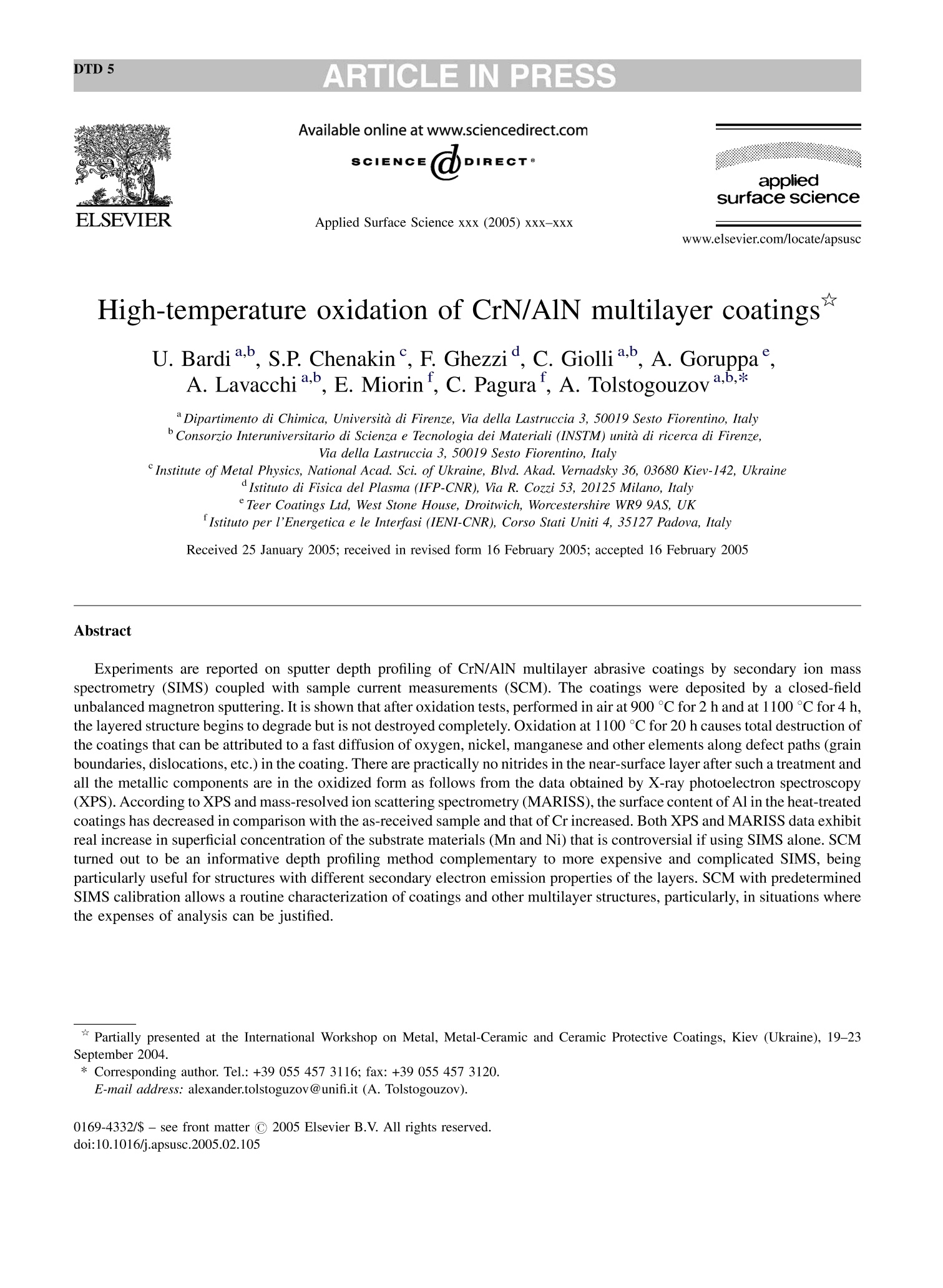
实验报告的是通过二次离子质谱仪(SIMS)对CrN/AlN高温氧化物多涂层进行的深度剖析.涂层是通过一个封闭非平衡的磁电管沉积成的.氧化是在900度下进行2小时,在1100度下进行4小时.
方案详情

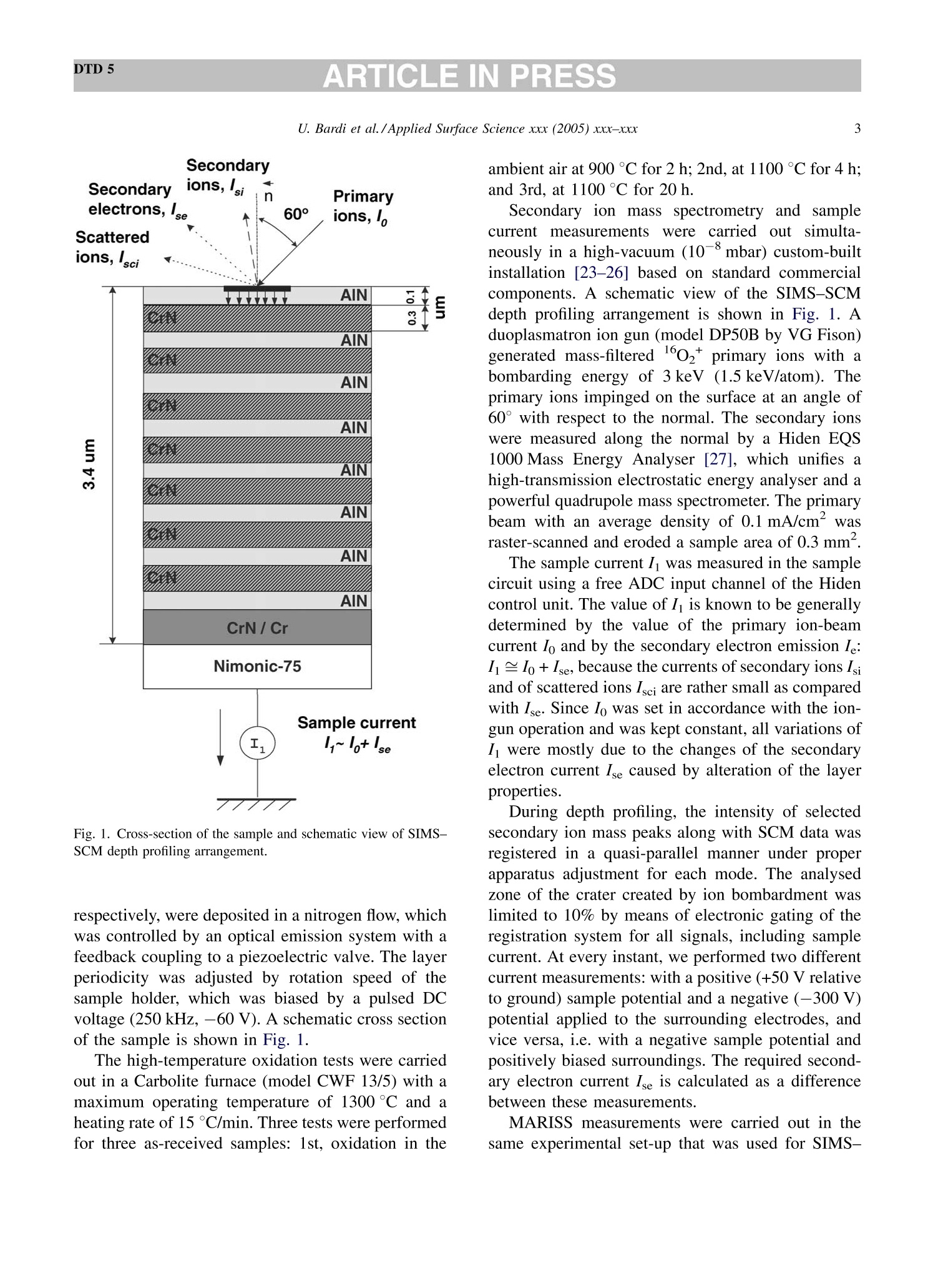
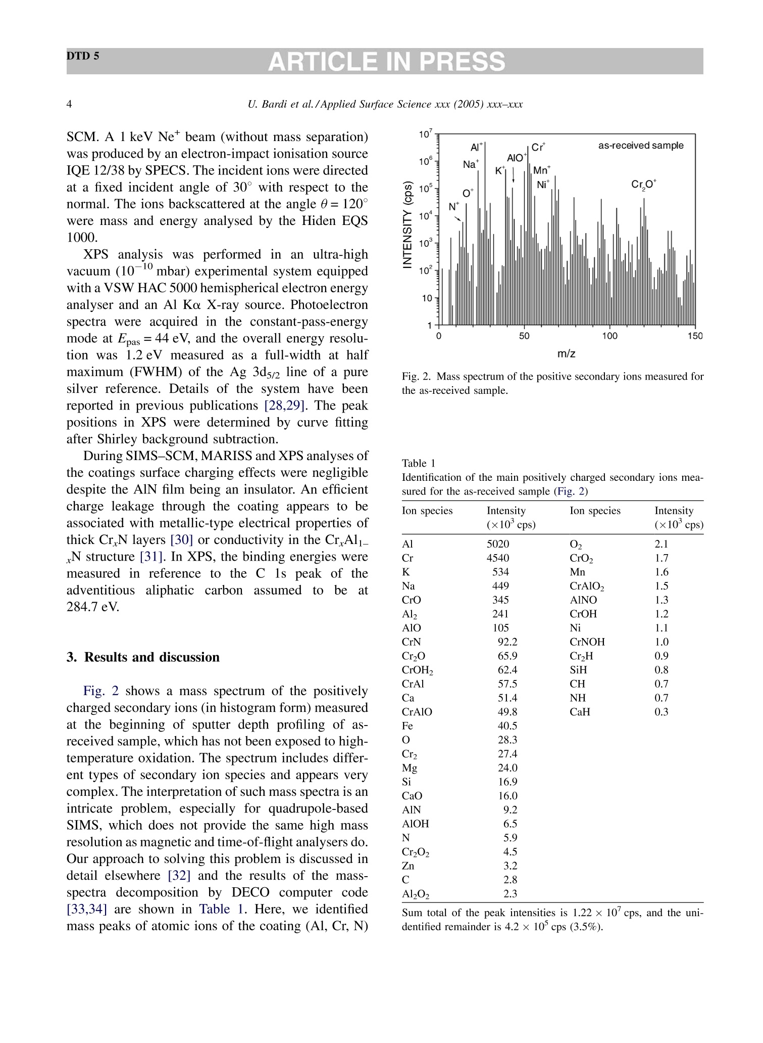
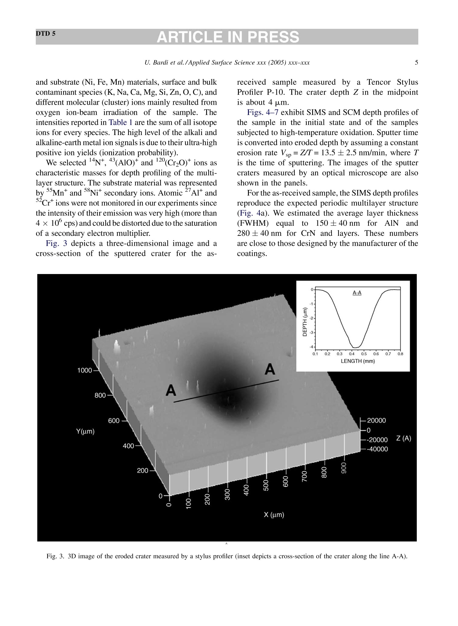
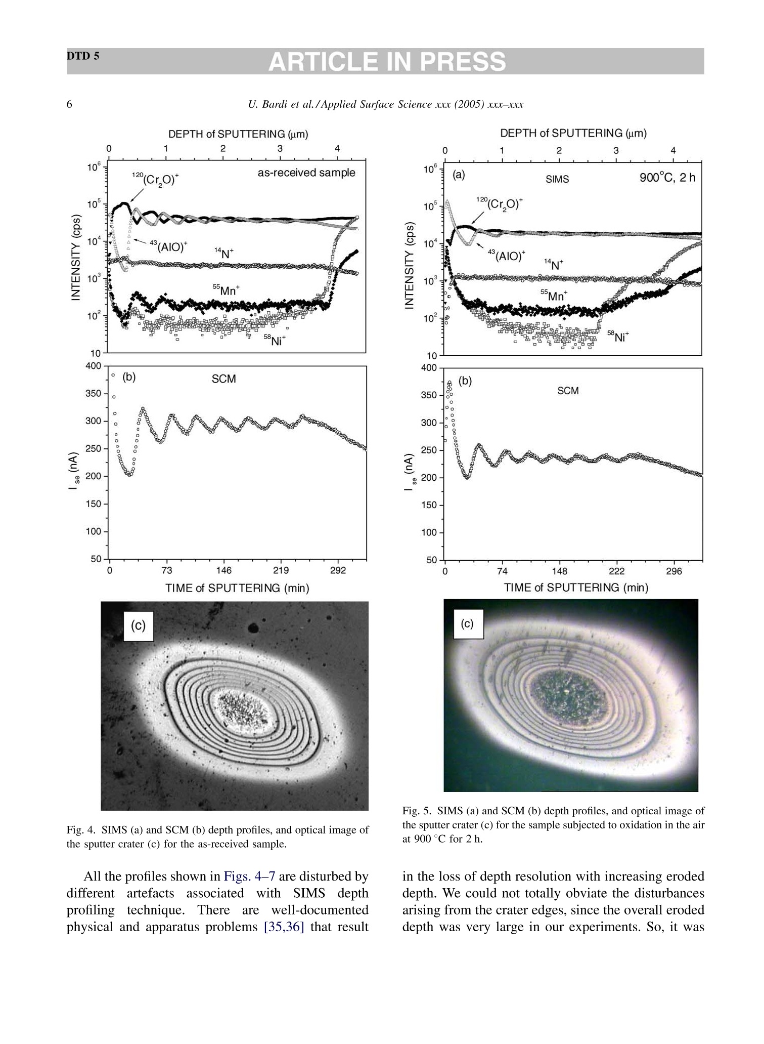
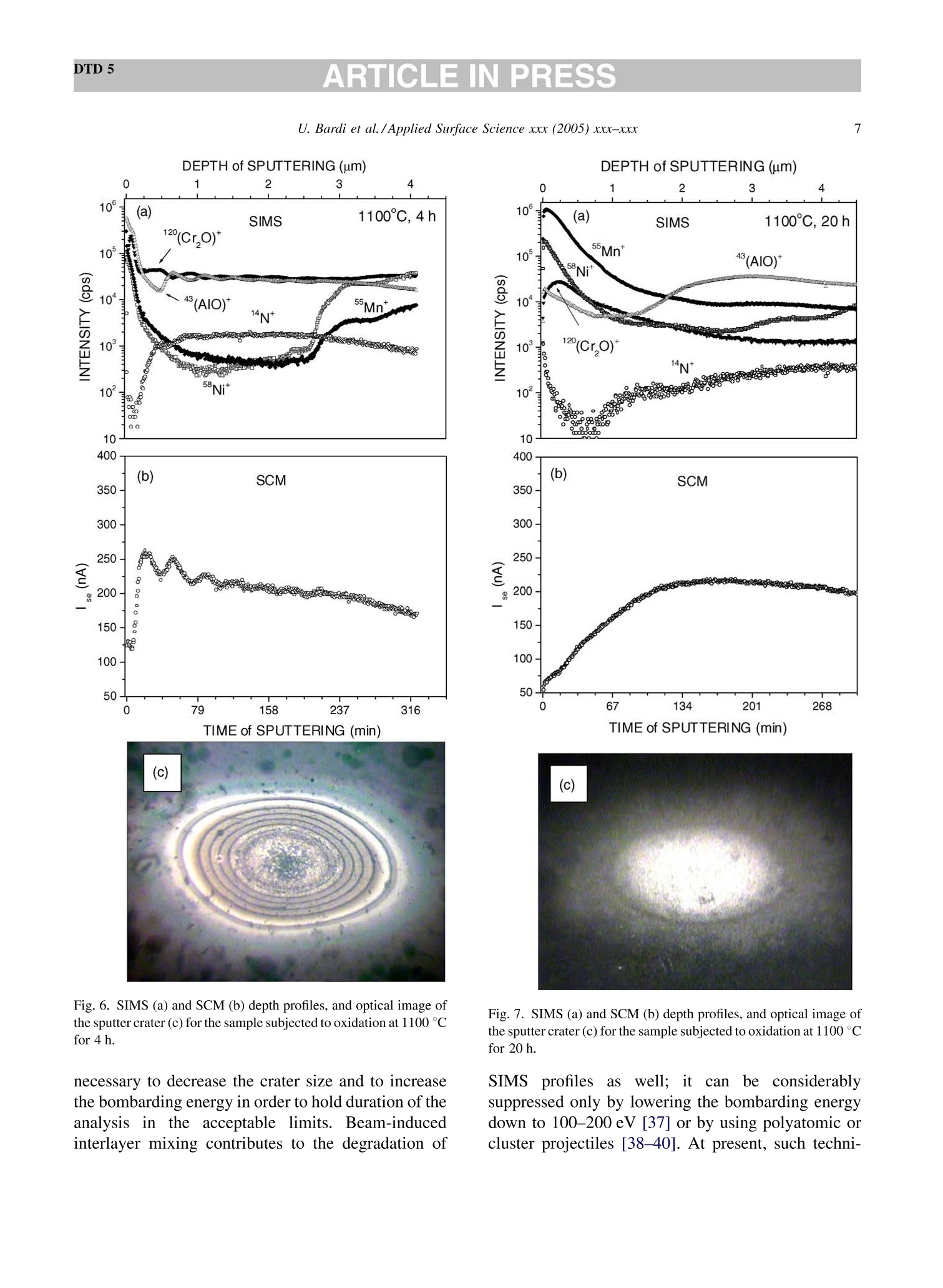
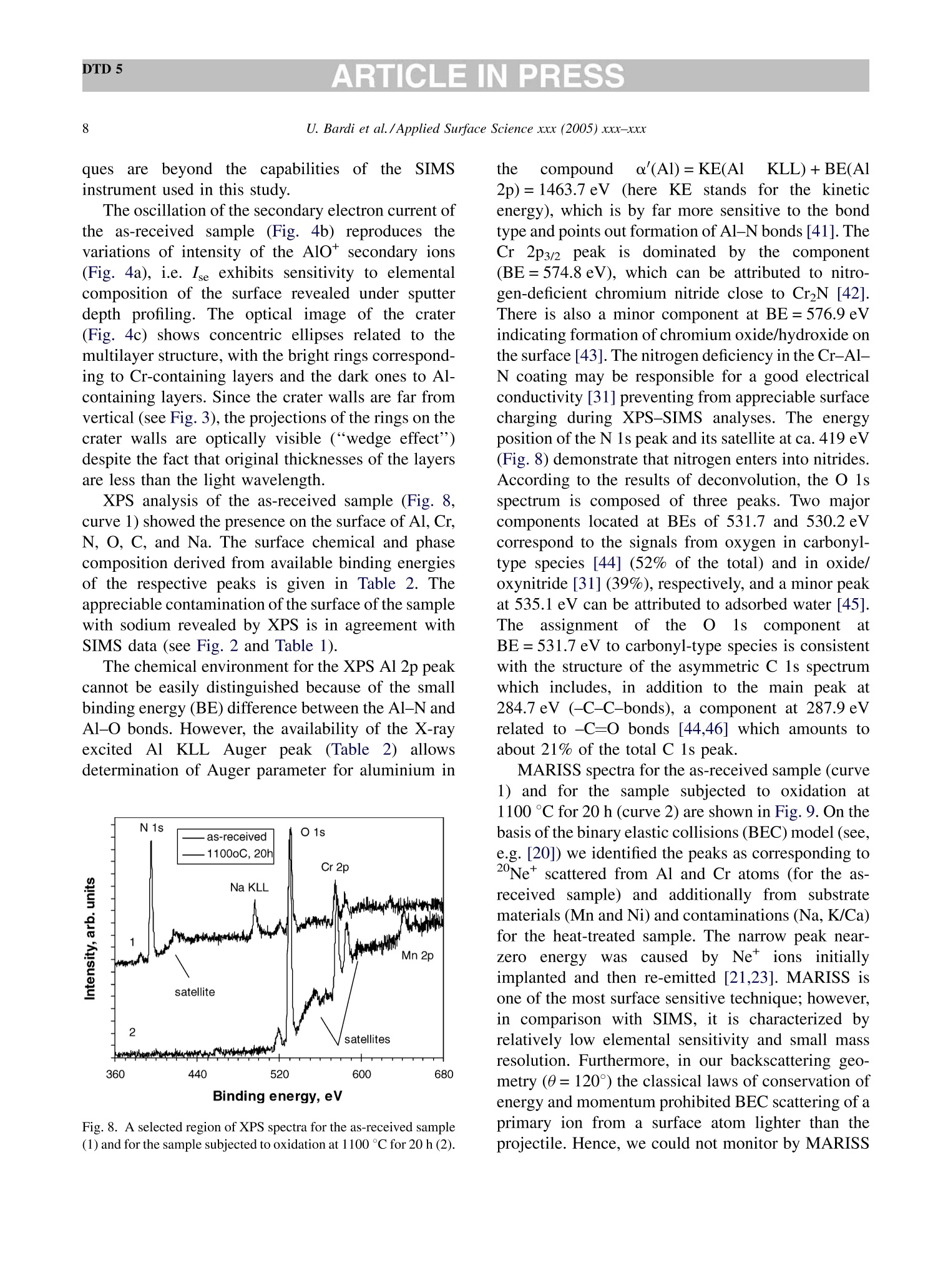
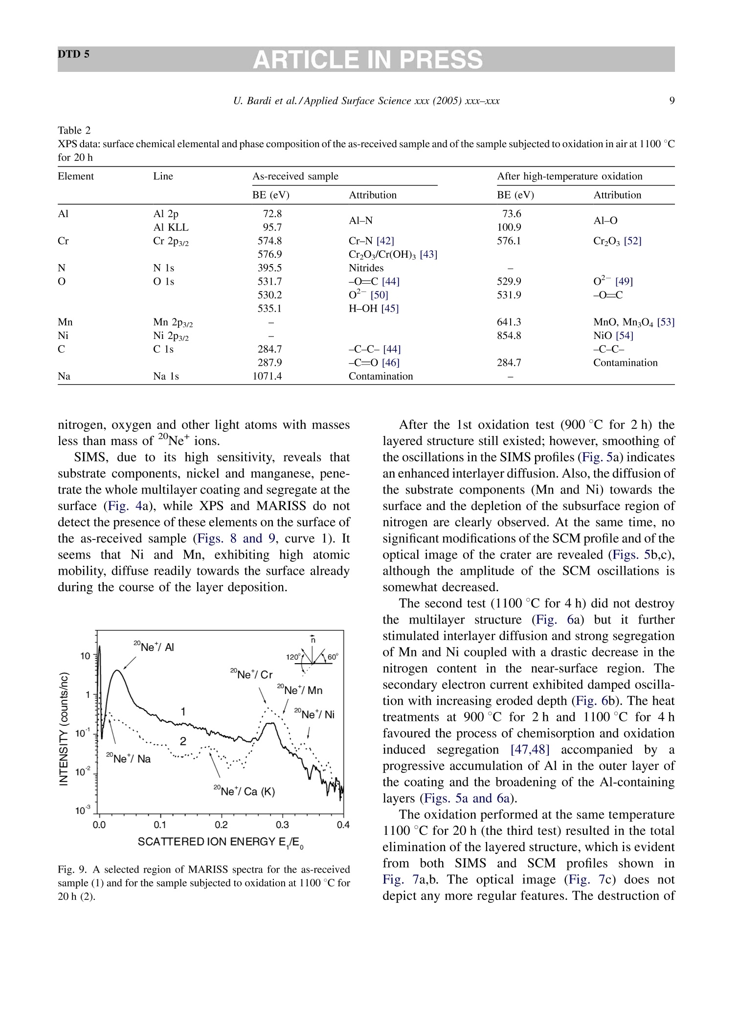
DTD 5ARTICLE IN PRESSApplied Surface Science xxx (2005) xxx-xxx DTD 5ARTICLE IN PRESS 11 Available online at www.sciencedirect.com appliedsurface science www.elsevier.com/locate/apsusc High-temperature oxidation of CrN/AlN multilayer coatings^☆ U. Bardi ab, S.P. Chenakin, F. Ghezzi, C. Giolli, A. Goruppa, A. Lavacchia.b,E. Miorin, C. Pagura, A. Tolstogouzov a,b,* “Dipartimento di Chimica, Universita di Firenze, Via della Lastruccia 3, 50019 Sesto Fiorentino, Italy °Consorzio Interuniversitario di Scienza e Tecnologia dei Materiali (INSTM) unita di ricerca di Firenze, Via della Lastruccia 3, 50019 Sesto Fiorentino, Italy Institute of Metal Physics, National Acad. Sci. of Ukraine, Blvd. Akad. Vernadsky 36, 03680 Kiev-142, Ukraine “Istituto di Fisica del Plasma (IFP-CNR), Via R. Cozzi 53, 20125 Milano, Italy Teer Coatings Ltd, West Stone House, Droitwich, Worcestershire WR9 9AS, UK 'Istituto per l'Energetica e le Interfasi (IENI-CNR), Corso Stati Uniti 4, 35127 Padova, Italy Received 25 January 2005; received in revised form 16 February 2005; accepted 16 February 2005 Abstract Experiments are reported on sputter depth profiling of CrN/AlN multilayer abrasive coatings by secondary ion massspectrometry (SIMS) coupled with sample current measurements (SCM). The coatings were deposited by a closed-fieldunbalanced magnetron sputtering. It is shown that after oxidation tests, performed in air at 900 ℃ for 2 h and at 1100 °C for 4 h,the layered structure begins to degrade but is not destroyed completely. Oxidation at 1100 °℃ for 20 h causes total destruction ofthe coatings that can be attributed to a fast diffusion of oxygen, nickel, manganese and other elements along defect paths (grainboundaries, dislocations, etc.) in the coating. There are practically no nitrides in the near-surface layer after such a treatment andall the metallic components are in the oxidized form as follows from the data obtained by X-ray photoelectron spectroscopy(XPS). According to XPS and mass-resolved ion scattering spectrometry (MARISS), the surface content of Al in the heat-treatedcoatings has decreased in comparison with the as-received sample and that of Cr increased. Both XPS and MARISS data exhibitreal increase in superficial concentration of the substrate materials (Mn and Ni) that is controversial if using SIMS alone. SCMturned out to be an informative depth profiling method complementary to more expensive and complicated SIMS, beingparticularly useful for structures with different secondary electron emission properties of the layers. SCM with predeterminedSIMS calibration allows a routine characterization of coatings and other multilayer structures, particularly, in situations wherethe expenses of analysis can be justified. "Partially presented at the International Workshop on Metal, Metal-Ceramic and Ceramic Protective Coatings, Kiev (Ukraine), 19-23September 2004. ( * Corresponding author. Tel.: +39 055 457 3 1 16; fax:+39 055 457 312 0 . ) ( E-mail address: alexander.tolstoguzov@unifi.it (A. Tolstogouzov). ) ( 0169-4332/$- see front ma t ter C 2005 Else v ier B.V. All r igh t s reserved. ) ( doi:10.1016/j.apsusc.2005.02.105 ) 2 U. Bardi et al./Applied Surface Science xxx (2005) xxx-xxx C 2005 Elsevier B.V. All rights reserved. PACS: 68.55.Nq; 82.80.Ms Keywords: Depth profiling; Mass-resolved ion scattering spectrometry (MARISS); Nitride multilayer coatings; Secondary ion massspectrometry (SIMS); X-ray photoelectron spectroscopy (XPS); Unbalanced magnetron sputtering High-temperature resistant coatings have beendeveloped for a variety of applications. When aconsiderable hardness is needed, such as for abrasivecoatings to be coupled with abradable ones for gapsealing applications, a promising :iavenue isthefabrication of complex multilayer structures. Amongstthem, metallic nitride and oxynitride films [1-6]manufactured by physical vapour deposition (PVD)techniques have proved to be very effective tools dueto enhanced mechanical properties (hardness, adhe-sion, wear, corrosion, and high-temperature resis-tances). The optimization of coatings deposition processesand understanding of the degradation mechanismsrequires post-growth characterization of the films,usually in terms of chemical composition, phasecomposition and microstructure by X-ray photoelec-tron spectroscopy and X-ray diffraction, secondaryand transmission electron microscopy, Raman spec-troscopy, etc.[7]. Less attention has been paid to theelemental depth profiling in spite of the fact that suchmeasurements enable monitoring interfaces and revealdegradation of the layered structures under differentconditions. This has motivated the present work, aimed atstudying the elemental depth profiles of the CrN/AlNmultilayer films subjected to high-temperature oxida-tion in air. The structures were developed by TeerCoatings [8] for application as abrasive coatings fortipping turbine blades. The depth profilingWasperformed by secondary ion massspectrometry(SIMS) [9,10] with appropriate calibration of thesputtering rate tbyyaasstyluslSprofiler. To obtaincomplementary information, we simultaneously mon-itored the variations of ion-induced secondary electronemission via current measurements in the samplecircuit. This simple but informative method (for areview, see, e.g. [11-16]) is named “sample-current measurements”(SCM) [17]. It exhibits high sensi-tivity to the interlayer boundaries, particularly, forstructures with different secondary electron emissionproperties of the layers and thus allows an integrateddepth profiling. In general, variations of secondaryelectron emission induced by electrons, ions andphotons have a long history in characterisation ofmetal overlayer growth, anda summary of itsapplications and principles may be found in [18]. X-ray photoelectron spectroscopy (XPS) [19] wasemployed in our study for surface chemical analysis ofthe samples, and low-energy ion scattering [20] wasenlisted to probe the outer atomic layer of the surface.In contrast to SIMS, the yield of the scattered ions isless sensitive to “matrix effect". It has been shown[21-25] that complementary mass separation ofscattereddions simplifies peakk identification andeliminates the overall background related to sputteringof the samples materials that allows avoiding anyadditional treatment of the spectra. In [21], Wittmaackdenoted this technique as mass-resolved ion scatteringspectrometry (MARISS) and we used MARISS as anadjuvant method for elemental analysis of the surface. 2. Experimental The coatings were deposited on a Nimonic-75superalloy substrate (Ni 75%, Cr 19%,Fe 5%, Mn 1%)using a closed-field unbalanced magnetron sputteringsystem with opposite Cr and Al targets. Beforedeposition, the substrate was polished by a diamondpaste down to 3 um and fixed on a cylindrical sampleholder in the vacuum chamber (P=4.7 × 10⁻⁴ Pa). Itwas cleaned by ion bombardment in an Ar plasmadischarge (PAr=0.2 Pa) and coated in sequence by abonding Cr layer (ca. 0.3 um), a transition CrN layer(ca. 0.2 um) and a gradual introduction of AlN (ca.0.1 um). Then, fourteen alternating layers of CrN andAlN with nominal layer widths of 0.3 and 0.1 um, 5 77 77 Fig. 1. Cross-section of the sample and schematic view of SIMS-SCM depth profiling arrangement. respectively, were deposited in a nitrogen flow, whichwas controlled by an optical emission system with afeedback coupling to a piezoelectric valve. The layerperiodicity was adjusted by rotation speed of thesample holder, which was biased by a pulsed DCvoltage (250 kHz, -60 V). A schematic cross sectionof the sample is shown in Fig. 1. The high-temperature oxidation tests were carriedout in a Carbolite furnace (model CWF 13/5) with amaximum operating temperature of 1300°C and aheating rate of 15 °C/min. Three tests were performedfor three as-received samples: 1st, oxidation in the ambient air at 900 C for 2 h; 2nd, at 1100 °C for 4h;and 3rd, at 1100 °C for 20 h. Secondary ion mass spectrometry and samplecurrent measurements were carried out simulta-neously in a high-vacuum (10-8mbar) custom-builtinstallation [23-26] based on standard commercialcomponents. A schematic view of the SIMS-SCMdepth profiling arrangement is shown in Fig. 1. Aduoplasmatron ion gun (model DP50B by VG Fison)generated mass-filtered 1602primary ions with abombarding energy of 3keV (1.5 keV/atom). Theprimary ions impinged on the surface at an angle of60°with respect to the normal. The secondary ionswere measured along the normal by a Hiden EQS1000 Mass Energy Analyser [27], which unifies ahigh-transmission electrostatic energy analyser and apowerful quadrupole mass spectrometer. The primarybeam with an average density of 0.1 mA/cm’wasraster-scanned and eroded a sample area of 0.3 mm . The sample current I was measured in the samplecircuit using a free ADC input channel of the Hidencontrol unit. The value of I is known to be generallydetermined by the value of the primary ion-beamcurrent Io and by the secondary electron emission Ie:I= Io + Ise, because the currents of secondary ions Isiand of scattered ions Isci are rather small as comparedwith Ise. Since Io was set in accordance with the ion-gun operation and was kept constant, all variations ofI were mostly due to the changes of the secondaryelectron current Ise caused by alteration of the layerproperties. During depth profiling, the intensity of selectedsecondary ion mass peaks along with SCM data wasregistered in a quasi-parallel manner under properapparatus adjustment for each mode. The analysedzone of the crater created by ion bombardment waslimited to 10% by means of electronic gating of theregistration system for all signals, including samplecurrent. At every instant, we performed two differentcurrent measurements: with a positive (+50 V relativeto ground) sample potential and a negative (-300V)potential applied to the surrounding electrodes, andvice versa, i.e. with a negative sample potential andpositively biased surroundings. The required second-ary electron current Ise is calculated as a differencebetween these measurements. MARISS measurements were carried out in thesame experimental set-up that was used for SIMS- SCM. A 1 keV Ne beam (without mass separation)was produced by an electron-impact ionisation sourceIQE 12/38 by SPECS. The incident ions were directedat a fixed incident angle of 30° with respect to thenormal. The ions backscattered at the angle 0=120°were mass and energy analysed by the Hiden EQS1000. XPS analysiss was performed in an ultra-highvacuum (10-10 mbar) experimental system equippedwith a VSW HAC 5000 hemispherical electron energyanalyser and an Al Ko X-ray source. Photoelectronspectra were acquired in the constant-pass-energymode at Epas=44 eV, and the overall energy resolu-tion was 1.2 eV measured as a full-width at halfmaximum (FWHM) of the Ag 3d5/2 line of a puresilver reference. Details of the system have beenreported in previous publications [28,29]. The peakpositions in XPS were determined by curve fittingafter Shirley background subtraction. During SIMS-SCM, MARISS and XPS analyses ofthe coatings surface cha、AINT crging effects were negligibledespite the AlN film being an insulator. An efficientcharge leakage through the coating appears to beassociated with metallic-type electrical properties ofthick CrN layers [30] or conductivity in the CrAl_N structure [31]. In XPS, the binding energies weremeasured in reference to the C 1ss peak of theadventitiousisaaliphatic carbonassumedtctobe at284.7eV. 3. Results and discussion Fig.2 shows a mass spectrum of the positivelycharged secondary ions (in histogram form) measuredat the beginning of sputter depth profiling of as-received sample, which has not been exposed to high-temperature oxidation. The spectrum includes differ-ent types of secondary ion species and appears verycomplex. The interpretation of such mass spectra is anintricate problem, especially for quadrupole-basedSIMS, which does not provide the same high massresolution as magnetic and time-of-flight analysers do.Our approach to solving this problem is discussed indetail elsewhere [32] and the results of the mass-spectra decomposition by DECO computer code[33,34] are shown in Table 1. Here, we identifiedmass peaks of atomic ions of the coating (Al, Cr, N) Fig. 2. Mass spectrum of the positive secondary ions measured forthe as-received sample. Table 1 Identification of the main positively charged secondary ions mea-sured for the as-received sample (Fig.2) Ion species Intensity Ion species Intensity (×10'cps) (×10'cps) 5020 02 2.1 4540 CrO2 1.7 534 Mn 1.6 449 CrAlO, 1.5 CrO 345 AlNO 1.3 Al, 241 CrOH 1.2 AlO 105 Ni 1.1 CrN 92.2 CrNOH 1.0 Cr2O 65.9 Cr2H CrOH, 62.4 SiH CrAl 57.5 CH Ca 51.4 NH CrA1O 49.8 CaH 0.3 40.5 28.3 27.4 24.0 16.9 CaO 16.0 AlN 9.2 AlOH 6.5 N 5.9 Cr202 4.5 Al202 Sum total of the peak intensities is 1.22×10cps, and the uni-dentified remainder is 4.2×10cps (3.5%). and substrate (Ni, Fe, Mn) materials, surface and bulkcontaminant species (K,Na,Ca, Mg, Si,Zn, O, C), anddifferent molecular (cluster) ions mainly resulted fromoxygen ion-beam irradiation of the sample. Theintensities reported in Table 1 are the sum of all isotopeions for every species. The high level of the alkali andalkaline-earth metal ion signals is due to their ultra-highpositive ion yields (ionization probability). We selected N*, 43(AlO)*and 120(CrO)* ions ascharacteristic masses for depth profiling of the multi-layer structure. The substrate material was representedby 55Mn*and 58Nit secondary ions. Atomic 27Al* andCr*ions were not monitored in our experiments sincethe intensity of their emission was very high (more than4×10°cps) and could be distorted due to the saturationof a secondary electron multiplier. Fig. 3 depicts a three-dimensional image and across-section of the sputtered crater for the as- receivedd sample measured by a Tencor StylusProfiler P-10. The crater depth Z in the midpointis about 4 um. Figs. 4-7 exhibit SIMS and SCM depth profiles ofthe sample in the initial state and of the samplessubjected to high-temperature oxidation. Sputter timeis converted into eroded depth by assuming a constanterosion rate Vsp=Z/T=13.5±2.5 nm/min, where Tis the time of sputtering. The images of the sputtercraters measured by an optical microscope are alsoshown in the panels. For the as-received sample, the SIMS depth profilesreproduce the expected periodic multilayer structure(Fig. 4a). We estimated the average layer thickness(FWHM)equal1to 150±40nmfor AlN and280 ±40nm for CrN and layers. These numbersare close to those designed by the manufacturer of thecoatings. Fig. 3. 3D image of the eroded crater measured by a stylus profiler (inset depicts a cross-section of the crater along the line A-A). 0 1 3 4 as-received sample 10°120(Cr,0)10°5-一>(AIO) 14N+ Z 10°Mn*120.Ni10400(b) SCM3501o300o250200150-100-50-0 73 146 219 292TIME of SPUTTERING (min)(c) Fig. 4. SIMS (a) and SCM (b) depth profiles, and optical image ofthe sputter crater (c) for the as-received sample. All the profiles shown in Figs. 4-7 are disturbed bydifferentartefact.sSassociatedwithSIMSdepthprofilingtt6echnique.Thereaarewell-documentedphysical and apparatus problems [35,36] that result DEPTH ofSPUTTERING (um) Fig. 5. SIMS (a) and SCM (b) depth profiles, and optical image ofthe sputter crater (c) for the sample subjected to oxidation in the airat 900°C for 2 h. in the loss of depth resolution with increasing erodeddepth. We could not totally obviate the disturbancesarising from the crater edges, since the overall erodeddepth was very large in our experiments. So, it was DEPTH of SPUTTERING (um) DEPTH of SPUTTERING(um) 0 2 3 4 Fig. 6. SIMS (a) and SCM (b) depth profiles, and optical image ofthe sputter crater (c) for the sample subjected to oxidation at 1100°℃for 4 h. Fig. 7. SIMS (a) and SCM (b) depth profiles, and optical image ofthe sputter crater(C) for the sample subjected to oxidation at 1100℃for 20 h. necessary to decrease the crater size and to increasethe bombarding energy in order to hold duration of theanalysisin the acceptable limits. ]Beam-inducedinterlayer mixing contributes to the degradation of SIMSSpprofilesaswell: it cannbe considerablysuppressed only by lowering the bombarding energydown to 100-200 eV [37] or by using polyatomic orcluster projectiles [38-40]. At present, such techni- ques are beyond the capabilities of theSIMSinstrument used in this study. The oscillation of the secondary electron current ofthe as-received sample (Fig.4b) reproduces thevariations of intensity of the Alo* secondary ions(Fig. 4a), i.e. Ise exhibits sensitivity to elementalcomposition of the surface revealed under sputterdepth profiling. The optical image of the crater(Fig. 4c) shows concentric ellipses related to themultilayer structure,with the bright rings correspond-ing to Cr-containing layers and the dark ones to Al-containing layers. Since the crater walls are far fromvertical (see Fig. 3), the projections of the rings on thecrater walls are optically visible (“wedge effect")despite the fact that original thicknesses of the layersare less than the light wavelength. XPS analysis of the as-received sample (Fig. 8,curve 1) showed the presence on the surface of Al, Cr,N, O, C, and Na. The surface chemical and phasecomposition derived from available binding energiesof the respective peaks is given in Table 2. Theappreciable contamination of the surface of the samplewith sodium revealed by XPS is in agreement withSIMS data (see Fig.2 and Table 1). The chemical environment for the XPS Al 2p peakcannot be easily distinguished because of the smallbinding energy (BE) difference between the Al-N andAl-O bonds. However, the availability of the X-rayexcited Al KLL Auger peak(Table 2) allowsdetermination of Auger parameter for aluminium in Fig. 8. A selected region of XPS spectra for the as-received sample(1) and for the sample subjected to oxidation at 1100°C for 20 h (2). the compound o'(Al)=KE(Al KLL)+BE(Al2p)=1463.7eV (here KE stands for the kineticenergy), which is by far more sensitive to the bondtype and points out formation of Al-N bonds [41]. TheCr 2p3/2 peakis dominated by the component(BE=574.8eV), which can be attributed to nitro-gen-deficient chromium nitride close to CrN [42].There is also a minor component at BE=576.9 eVindicating formation of chromium oxide/hydroxide onthe surface [43]. The nitrogen deficiency in the Cr-Al-N coating may be responsible for a good electricalconductivity [31] preventing from appreciable surfacecharging during XPS-SIMS analyses. The energyposition of the N 1s peak and its satellite at ca. 419 eV(Fig. 8) demonstrate that nitrogen enters into nitrides.According to the results of deconvolution, the O 1sspectrum is composed of three peaks. Two majorcomponents located at BEs of 531.7 and 530.2 eVcorrespond to the signals from oxygen in carbonyl-type species [44] (52% of the total) and in oxide/oxynitride [31](39%),respectively, and a minor peakat 535.1 eV can be attributed to adsorbed water [45].Theassignment of theeo11s component atBE=531.7 eV to carbonyl-type species is consistentwith the structure of the asymmetric C 1s spectrumwhich includes, in addition to the main peak at284.7 eV (-C-C-bonds), a component at 287.9 eVrelated to -C=O bonds [44,46] which amounts toabout 21% of the total C 1s peak. MARISS spectra for the as-received sample (curve1) and for the sample subjected to oxidation at1100 ℃ for 20 h (curve 2) are shown in Fig. 9. On thebasis of the binary elastic collisions (BEC) model (see,e.g. [20]) we identified the peaks as corresponding to2 Ne scattered from Al and Cr atoms (for the as-received sample) and additionally from substratematerials (Mn and Ni) and contaminations (Na,K/Ca)for the heat-treated sample. The narrow peak near-zero energy wascaused by Ne* ions initiallyimplanted and then re-emitted [21,23]. MARISS isone of the most surface sensitive technique; however,in comparison with SIMS, it is characterized byrelatively low elemental sensitivity and small massresolution. Furthermore, in our backscattering geo-metry (0=120°) the classical laws of conservation ofenergy and momentum prohibited BEC scattering of aprimary ion from a surface atom lighter than theprojectile. Hence, we could not monitor by MARISS Table 2 XPS data: surface chemical elemental and phase composition of the as-received sample and of the sample subjected to oxidation in air at 1100℃ for 20 h Element Line As-received sample After high-temperature oxidation BE (eV) Attribution BE (eV) Attribution Al Al 2p 72.8 Al-N 73.6 Al-O Al KLL 95.7 100.9 Cr Cr 2p3/2 574.8 Cr-N [42] 576.1 Cr2O3 [52] 576.9 Cr2O3/Cr(OH)3[43] N N 1s 395.5 Nitrides o O 1s 531.7 -O=C [44] 529.9 O-[49] 530.2 o²-[[50] 531.9 -O=C 535.1 H-OH [45] Mn Mn 2p3/2 641.3 MnO, Mn304 [53] Ni Ni 2p3/2 854.8 NiO [54] C 1s 284.7 -C-C-[44] -C-C- 287.9 -C-O [46] 284.7 Contamination Na Na 1s 1071.4 Contamination nitrogen, oxygen and other light atoms with massesless than mass of Neions. SIMS, due to its high sensitivity, reveals thatsubstrate components, nickel and manganese, pene-trate the whole multilayer coating and segregate at thesurface (Fig. 4a), while XPS and MARISS do notdetect the presence of these elements on the surface ofthe as-received sample (Figs. 8 and 9, curve 1). Itseems that Ni and Mn, exhibiting high atomicmobility, diffuse readily towards the surface alreadyduring the course of the layer deposition. Fig. 9. A selected region of MARISS spectra for the as-receivedsample (1) and for the sample subjected to oxidation at 1100 ℃ for20h (2). After the 1st oxidation test (900℃ for 2 h) thelayered structure still existed; however, smoothing ofthe oscillations in the SIMS profiles (Fig.5a) indicatesan enhanced interlayer diffusion. Also, the diffusion ofthe substrate components (Mn and Ni) towards thesurface and the depletion of the subsurface region ofnitrogen are clearly observed. At the same time, nosignificant modifications of the SCM profile and of theoptical image of the crater are revealed (Figs. 5b,c),although the amplitude of the SCM oscillations issomewhat decreased. The second test (1100C for 4 h) did not destroythe multilayer structure (Fig. 6a) but it furtherstimulated interlayer diffusion and strong segregationof Mn and Ni coupled with a drastic decrease in thenitrogen content in the near-surface region. Thesecondary electron current exhibited damped oscilla-tion with increasing eroded depth (Fig. 6b). The heattreatments at 900°C for 2h and 1100°C for 4 hfavoured the process of chemisorption and oxidationinducedsegregation[47,48]accompaniedbyyaprogressive accumulation of Al in the outer layer ofthe coating and the broadening of the Al-containinglayers (Figs. 5a and 6a). The oxidation performed at the same temperature1100℃ for 20 h (the third test) resulted in the totalelimination of the layered structure, which is evidentfrom both SIMSand SCM profiles shownimFig. 7a,b. The optical image (Fig. 7c) does notdepict any more regular features. The destruction of the coating structure can be attributed to a fastdiffusion of N,O, Ni, Mn and other elements alongdefect paths (grain boundaries, dislocations, etc.) inboth directions, towards the surface and inward thecoating. Accumulation of the substrate components Mn andNi in the near-surface region of the coating occurringdue to strong diffusion of these elements during heattreatment of the sample in the air at 1100 ℃ for 20 h isclearly demonstrated bby respective SIMS depthprofiles (Fig. 7a). An intense emission of the Mnand Ni secondary ions is not caused solely byenhancement of respective secondary ion yields due tooxidation but also reflects an appreciable increase inthe concentration of these components in the near-surface region which is corroborated by XPS andMARISS analyses of this sample. Indeed, as distinctfromnas-receivveedd sample (Fig. 8, curve1),apronounced Mn 2p (Fig. 8, curve 2) and a small Ni2p peaks are now detected in the spectra.The bindingenergies of these peaks indicate that they are formedpredominantly by photoelectrons emitted from moststable oxides (Table 2). According to XPS-MARISS data, the surfacecontent of Al in the heat-treated coating has decreasedin comparison with the as-received sample and that ofCr increased. After high-temperature oxidation nonitrogen is detected at the surface while oxygenconcentration rises significantly (Fig. 8). The maincomponent of the O 1s spectrum at BE=529.9 e Vpoints out predominant formation of the metal-oxide(O”) species and seems to be largely associated withCr203 [49], thoughaca small contribution of thecarbonyl-type bonds isalso present. There; arepractically no nitrides in the surface layer, and allthe metallic components in the heat-treated coating arein the oxidized form as follows from their bindingenergies (Table 2) and as is also indicated by a satelliteof the O 1s peak at ca. 555 eV (Fig.8, curve2). Theemergence of a satellite of the Cr 2p peak at ca. 598 eV(Fig. 8, spectrum 2) provides an evidence of thetrivalent state of chromium in oxide [50]. In theoxidized sample, the Al 2p binding energy and Augerparameter for aluminium (Al)=1459.3 eVaresomewhatlower than those reported for Al2O3[41,51] that may indicate formation of oxygen-deficient Al2O3 or/and of complex Al-Cr-O oxide[51]. 4. Summary The results of the present study provide a detailedcharacterization of PVD fabricated multilayer CrN/AlN coatings and their resistance to high-temperatureoxidation in air. Our focus is on the SIMS-SCM depthprofiling of the coatings, which revealed degradationof the layered structure under high-temperatureoxidation tests in the air. It was found that heattreatments of the nitride multilayer coating at 900 °℃for 2h and at 1100°C for 4 h stimulated interlayerdiffusion, enhanced segregation of the substratecomponents (Mn, Ni), brought about a progressivedepletion of the near-surface region of nitrogen but didnot destroy completely the layered structure. Holdingthe coating in the air at 1100℃ for 20 h eliminated thelayered structure and resulted in the full oxidation ofthe surface region accompanied by a strong diffusionof the substrate components towards the surface. XPSand MARISS have proved a real increase in superficialconcentration of the substrate materials (Mn and Ni)that is controversial, if using SIMS alone. One of thefindings of the present work is that the sample currentmeasurements are capable of monitoring interfaces inthe multilayer structure as the more complex SIMStechnique does. Using SCM with predeterminedcalibration by SIMS allows a routine characterizationof coatings and other multilayer structures, particu-larly, in situations where the expenses of analysis canbe justified. Acknowledgement The present work was supported by ABRANEWproject RS0098 (FP5 Programme). ( References ) [1] P. Verardi, M. Dinescu, C. Gerardi, M. Mirenghi, V. Sandu,Appl. Surf. Sci. 109-110 (1997) 371. [2] C. Emery, A.R. Chourasia, P. Yashar, J. Electron Spectrosc.Relat. Phenom. 104 (1999) 312. [3] N. Duez, B. Mutel, O. Dessaux, P. Goudmand, J. Grimblot,Surf. Coat. Technol. 125 (2000) 79. [4] A. Barata, L. Cunha, C. Moura, Thin Solid Films 388/389(2001) 501. ( [5] C. L eyens, M. P e ters, P.Eh. Hovsepian, D.B. Le w is, Q. Luo, W.-D. Miinz, Surf. Coat.Technol. 1 5 5 (2002) 10 3 . ) ( [6] G .S. Kim, S . Y. Le e , J.H. Hahn, S . Y. L e e, S u rf. Coat. Technol. 171(2003) 91. ) ( [7] J.C. Vickerman ( Ed.), Surface Analysis-The P r incipal Tech-niques, Wiley, Chichester, 1997. ) ( [8] Teer Coatings Ltd, West Stone House, Droitwich, W orcester- shire WR9 9AS, UK. ) ( [9] A. Benninghoven, F.G. Rudenauer, H.W. Werner, SecondaryIon Mass S pectrometry, Wiley, New York, 1 989. ) ( [ 1 0] R.G. W ilson, F.A. Stevie, C.W. Magee, S econdary Ion Mass Spectrometry: A Practical Handbook for Depth Profiling andBulk I mpurity Analysis, Wiley, New Y ork, 1989. ) ( [ 1 1] P .C. Zalm, L .J. Beckers, Surf. Sci. 152/153 (1985) 135. ) ( [12] A. Tolstogouzov, T. Kitaeva, Pisma v Zhurnal Teknicheskoi F iziki 20 (1994) 3 7 ( in Russian). ) ( [13] K. Wittmaack, Nucl. Instrum. Methods B 115 (1996) 288. ) ( [14] K. Wittmaack, Surf. Sci. 419 (1999) 249. ) ( [15]Y . Kataoka, K. Wittmaack, Surf. Sc i . 424 (1999) 29 9 . ) ( [ 1 6] M .A. K a rolewski, Surf. S c i. 517 (2002) 1 3 8. ) ( [ 1 7] A . Tolstogouzov, C.L. Greenwood, P o verkhnost’(R u ss.) 12 (2002) 33. ) ( [18] C. Argile, G.E. Rhead, S urf. Sci. Rep. 10 (1989) 277. ) ( [19] B . R atner, D . Castner, i n: J.C. Vickerman (Ed.), Surface Analy- sis-The Principal Techniques, W i ley, C h ichester, 1997 p . 43. ) ( [20] E . Taglauer, in: J.C. Vickerman ( Ed.), Surface Analysis-The P rincipal Techniques, Wiley, Chichester, 1 9 97, p . 215. ) ( [21] K .W i ttmaack, Su r f. Sci. 3 4 5 (1996) 11 0 . ) ( [22] K . F ranzreb, A . Pratt,S. Splinter, P.A.W. van der Heide, Surf. Interface Anal. 26 (1998) 597. ) [23] A. Tolstogouzov, S. Daolio, C. Pagura, Surf.Sci. 441(1999) 213. ( [24] S. Daolio, C. Pagura, A . Tolstogouzov, Appl. S u rf. Sci. 222(2004)166. ) ( [25] A . Tolstogouzov,S. D a olio,C. Pagura,Nucl. Instrum. MethodsB183 (2001)116. ) ( [26] A . Tolstogouzov, S. Daolio, C. Pagura, C.L. Greenwood, Int. J.Mass Spectrom. 2 14 ( 2002) 327. ) ( [27] Hiden Analytical Ltd, 420 Europe Boulevard,WarringtonWA5 7UN, England. ) ( [28] A . L avacchi,B. Cortigiani, G . R o vida, U. Bardi, A. Atrei, R . Angelucci, L . D o ri, S . N i coletti, A. Poggi, Sens. Actuators B 71 ( 2000)123. ) ( [29] E . G alvanetto, F . P. Galliano, F. Borgioli, U . Bardi, A. L a vac-chi, Thin Solid Films 384 (2001) 223. ) ( [30] E . Martinez, R. Sanjines,O. Banakh, F. L evy, Thin Solid F ilms 447-448 (2004) 332. ) ( [31] R . Sanjines, O . Banakh, C. Rojas, P.E. Schmid, F. L e v y, Thi n S olid Films 420-421 ( 2002) 3 12. ) ( [32] U . B ardi, S. C aporali, S .P. Chenakin, A . Lavacchi, E. Mi o rin, C. P agura, A. Tolstogouzov, S u rf. C o at. Technol., in p r ess ( http:// a uthors . elsevier.com/sd/ a rti c le/S0257897204011910). ) ( [33] A . T olstogouzov, E u r. Microsc. Anal. 3 (1997) 17 . ) ( [34] E . L aptev, u npublished d a ta. ) ( [35] H.W. W erner, P.R. Boudewijn, i n : A .W. C z anderna, T.E. M adey, C.J. Powell (Eds.), Beam E f fects, Surface Topography, and Depth Profiling in Surface Analysis, P l enum Pr e ss, New York, 1 998, p. 355. ) ( [36] S. Hofmann, Rep. P r og. Phys. 61 (1998)82 7 . ) ( [37] M .G. D o wsett, Appl. Su r f. Sci. 2 0 3-204 (2003) 5. ) ( [38] G . G illen, M . W a lker, P. T h ompson, J. Ben n ett, J. Vac. Sci . Technol. B 1 8 ( 2000) 503. ) ( [39] J . Matsuo, C. Okubo, T. Seki, T. Aoki, N. Toyoda, I. Ya m ada, Nucl. Instrum. Methods B219-B220 (2004)463. ) ( [40] S . Sun, C. Szakal, T. Roll, P. Mazarov, A. Wucher, N. Wino- g rad, Surf. Interface Anal. 36 (2004) 1367. ) ( [41] J.C. Sanchez-Lopez, M .D. A l cala, C. R e al, A . F e rnandez, Nanostruct. Mater. 11 (1999) 249. ) ( [42] O .Nishimura, K. Yabe, M. Iw a ki, J. E l ectron Spectrosc.Relat.Phenom. 49 (1989) 335. ) ( [43] F .M. C apece, V. Dicastro, C. Furlani,G. Mattogno, C. Fragale, M . Gargano, M . Rossi,J. Electron Spectrosc. Relat. P henom. 27 ( 1982) 119. ) ( [44] T. Belmonte, J.M. Thiebaut, D . M ezerette, J. Phys.D: Appl. Phys. 35 (2002) 1 919. ) ( [45] P .D. S chulze, S.L. Shaffer, R .L. H ance,D. L . Utley, J. Vac. Sci.Technol. A1 (1983) 97. ) ( [46] J . Li, Q. Zhang, S.F. Yoon, J. Ahn, Q. Zhou,S. Wang, D. Yang,Q. W ang, J. Appl. Phys. 92 (2002) 6275. ) ( [47] D . Tomanek, S. Mukherjee, V. Kumar, K.H. Bennemann, Surf.Sci. 114 (1982) 1 1 . ) ( [48] S .P. C henakin, M etallofizika i N o veishie Tekhnologii 24 (12)(2002) 1 665 ( in Russian). ) ( [49] W .Y. Howng, R.J. Thorn, J. C h em. Phys. Solids 41 ( 1 9 80) 75. ) ( [50] A.M. Salvi, J .E. Castle, J.F. Watts, E. Desimoni, A ppl. Surf.Sci. 90 (1995) 333. ) ( [51 ] T .L. B arr, J. Vac. Sci. Technol. A 9 (1991) 17 9 3. ) ( [52] G.C. Allen, S.J. H arris,J.A. Jutson, J.M. D y ke, Appl. Surf. Sci. 37(1989)111. ) ( [53] B .R. S trohmeier, D.M. H ercules, J . Phys. Chem. 8 8 (1984) 4922. ) ( [54] C.P. Li, A. Proctor, D.M. Hercules, Appl. Spectrosc.38(1984) 880. )
确定
还剩9页未读,是否继续阅读?


北京英格海德分析技术有限公司为您提供《CrN/AlN多涂层中高温氧化检测方案(二次离子质谱)》,该方案主要用于其他中高温氧化检测,参考标准--,《CrN/AlN多涂层中高温氧化检测方案(二次离子质谱)》用到的仪器有二次离子质谱探针
推荐专场


相关方案
更多