


方案详情
文
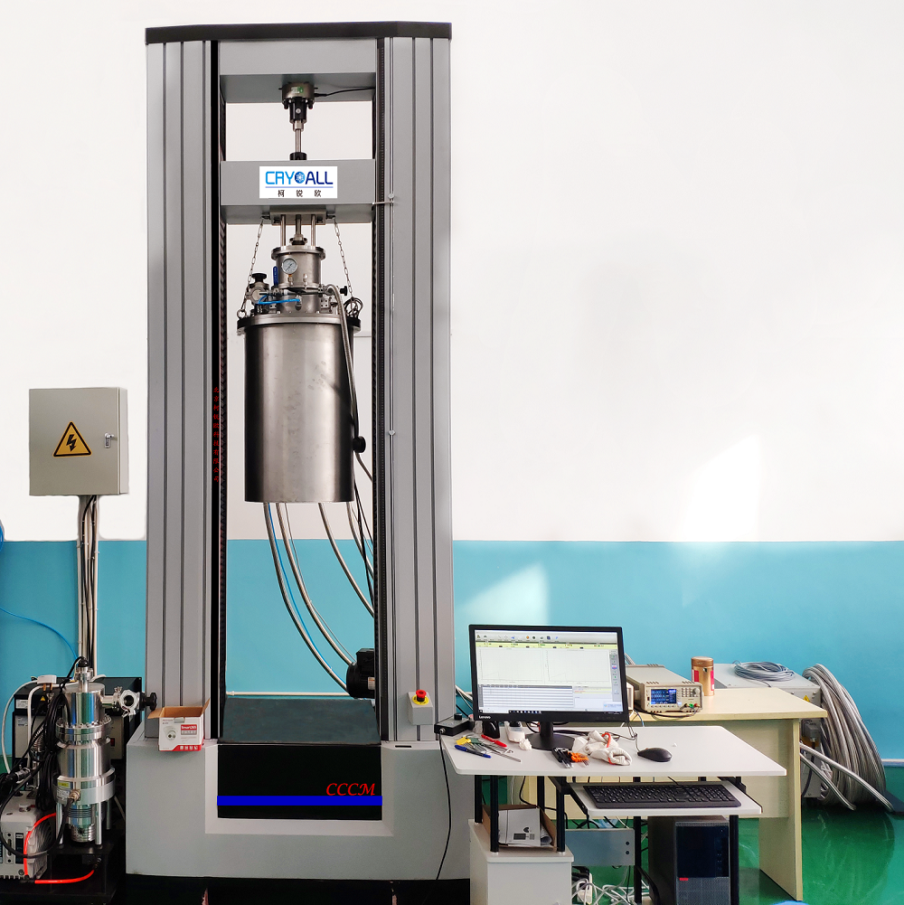
材料在低温下常常表现出“奇异”的力学行为。获得材料在低温区各温度点的力学性能数据才能认识材料随温度变化的力学行为,进而更深入地揭示材料力学行为中的规律。精确测量材料在低温环境中的力学性能,对材料、力学和物理等基础研究和高精技术应用发展具有重要的意义。要进行低温下的材料力学行为研究,材料低温力学性能测试系统是必不可少的重要装备之一。如2014年9月,Science 杂志报道了 CrMnFeCoNi 高熵合金优异的低温力学性能(A fracture-resistant high-entropy alloy for cryogenic applications,Science 2014: Vol. 345 no. 6201 pp. 1153-1158 DOI: 10.1126/science.1254581),此项成果的取得,离不开美国劳伦斯-伯克利国家实验室低温力学性能测试装备的支持。
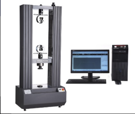
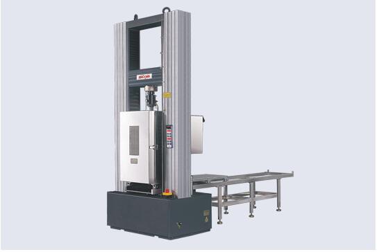
中国科学院理化技术研究所经过二十多年的研制和积累,开发出低温综合力学测试系统,此系统能进行材料低温环境(4.2K—300K(-269℃—室温)温区内任意温度)的力学性能测试,包括:拉伸、压缩、弯曲、剪切、扭转、断裂韧度等静态力学性能;疲劳裂纹扩展速率;拉拉疲劳、拉压疲劳、压压疲劳、扭转疲劳、拉(压)扭复合疲劳等疲劳性能测试。同时,还包括超导材料(低温超导线材、高温超导带材)加载电流时的力学性能、电学性能测试;非标试样和零部件的低温力学性能测试。
方案详情

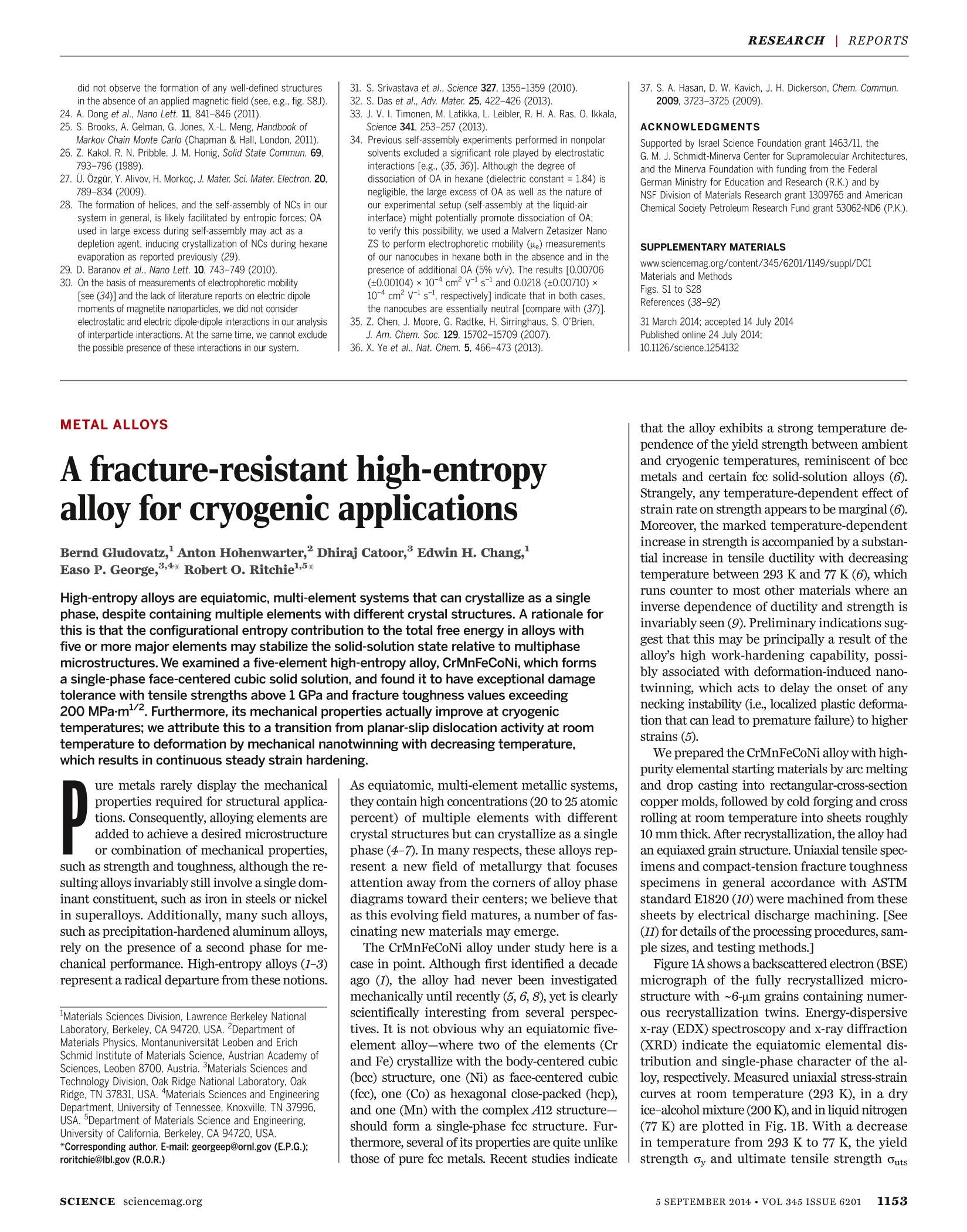
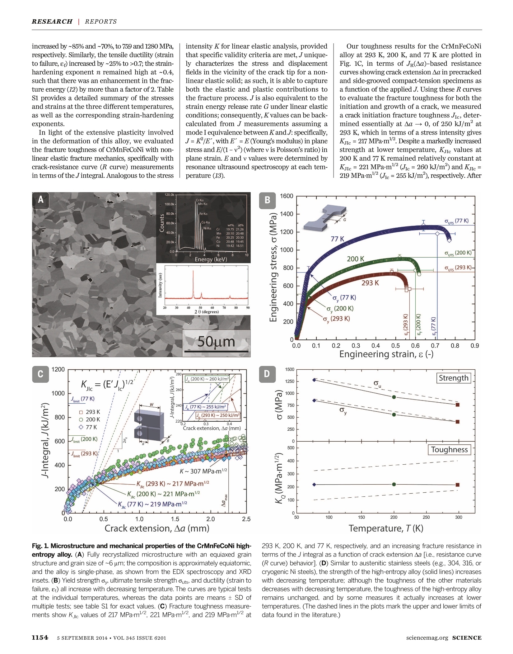
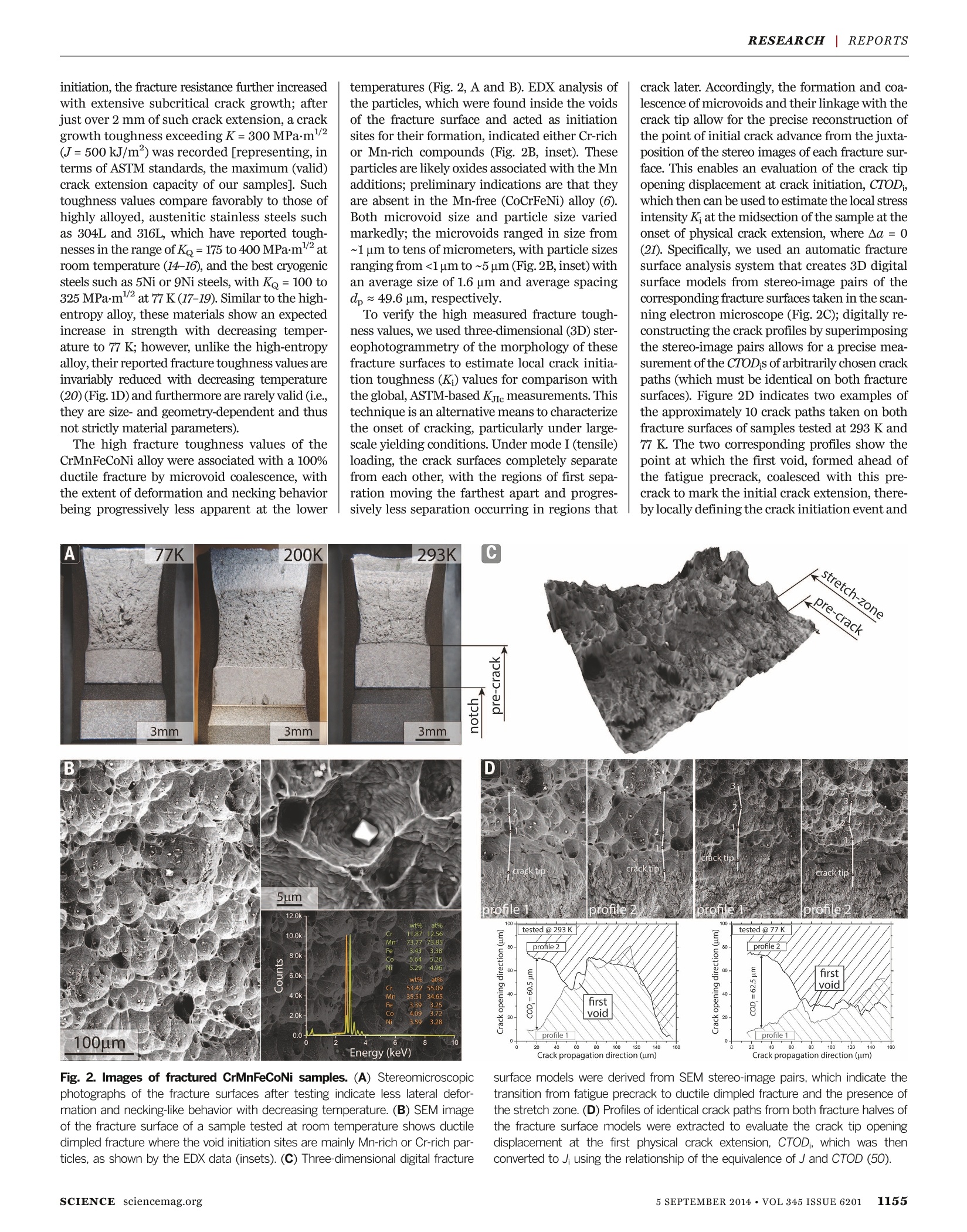
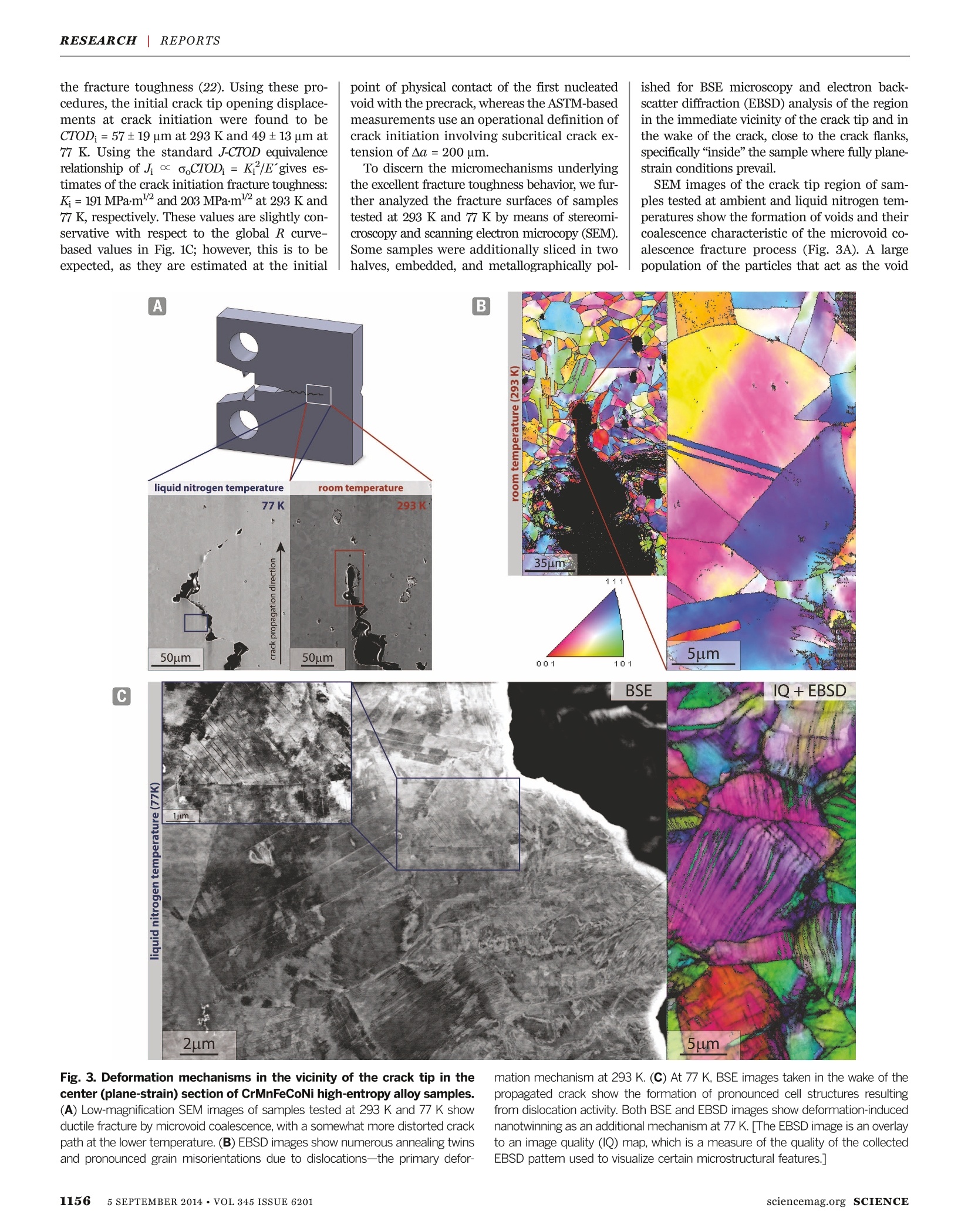
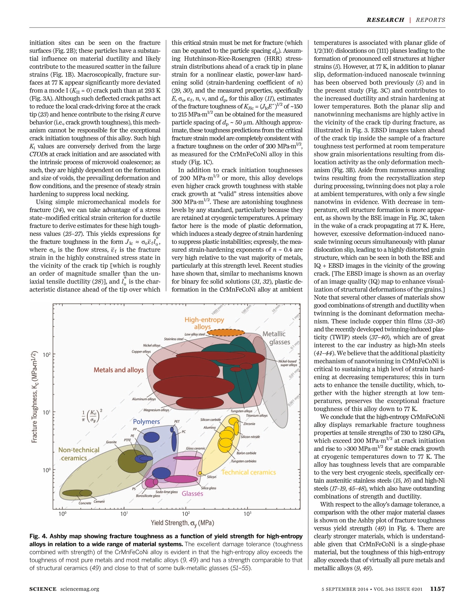
A fracture-resistant high-entropy alloy for cryogenic applicationsBernd Gludovatz et al.Science 345,1153(2014);ScienceAAAAS RESEARCH REPORTS DOI: 10.1126/science.1254581 This copy is for your personal, non-commercial use only. If you wish to distribute this article to others, you can order high-quality copies for yourcolleagues, clients, or customers by clicking here. The following resources related to this article are available online atwww.sciencemag.org (this information is current as of September 10, 2014): Updated information and services, including high-resolution figures, can be found in the onlineversion of this article at: http://www.sciencemag.org/content/345/6201/1153.full.html Supporting Online Material can be found at: http://www.sciencemag.org/content/suppl/2014/09/03/345.6201.1153.DC1.html This article appears in the following subject collections: Materials Science Permission to republish or repurpose articles or portions of articles can be obtained byfollowing the guidelines here. This article cites 45 articles, 2 of which can be accessed free: http://www.sciencemag.org/content/345/6201/1153.full.html#ref-list-1 http://www.sciencemag.org/cgi/collection/mat_sci ( Science (print ISSN 0 036-8075; online ISSN 1095-9203) is published weekly, except the last week in December, by theAmerican Association for the Advancement of Science, 1200 N ew York Avenue NW, Washington, DC 2000 e: 5 . Copyright2014 by the A merican Association fo r the A d vancement of S c ience; all r ights reserved. The title Sc i ence is aregistered trademark of AAAS. ) ( did not o bserve the f o rmation of any well-defined st r ucture s i n the absence of an a p plied magnetic field (s e e, e.g., f ig. S8J). 2 4. A . D ong et al. , Nano Lett. 11 , 841 - 846 (2011). ) ( 2 5. S . Brooks, A . G elman, G . J o nes, X . -L. Meng, Handbook of M arkov Chain M onte Carlo (Chapman & H a ll, London, 2011 ) ) ( 2 6. Z . K akol, R. N. Pribble, J. M . H onig, Solid State Commun. 6 9 . 793-796 ( 1989). ) 27. 0.Ozgur, Y. Alivov, H. Morkoc, J. Mater. Sci. Mater. Electron. 20,789-834(2009). 28. The formation of helices, and the self-assembly of NCs in oursystem in general, is likely facilitated by entropic forces; OAused in large excess during self-assembly may act as adepletion agent, inducing crystallization of NCs during hexaneevaporation as reported previously (29). 29. D. Baranov et al., Nano Lett. 10, 743-749 (2010). 30. On the basis of measurements of electrophoretic mobility[see (34)] and the lack of literature reports on electric dipolemoments of magnetite nanoparticles, we did not considerelectrostatic and electric dipole-dipole interactions in our analysisof interparticle interactions. At the same time, we cannot excludethe possible presence of these interactions in our system. 31. S. Srivastava et al., Science 327, 1355-1359(2010). ( 3 2. S . D as et al.. Adv. Mater. 25, 422- 4 2 6 (2 0 13). ) ( 3 3.J . V.I. T im onen, M . Latikka, L . Leibler, R . H . A. R as, O. I kkala, Science 341, 253-257 (2013). ) 34. Previous self-assembly experiments performed in nonpolarsolvents excluded a significant role played by electrostaticinteractions [e.g., (35, 36)]. Although the degree ofdissociation of OA in hexane (dielectric constant = 1.84) isnegligible, the large excess of OA as well as the nature ofour experimental setup (self-assembly at the liquid-airinterface) might potentially promote dissociation of OA;to verify this possibility, weused a Malvern Zetasizer NanoZS to perform electrophoretic mobility (He) measurementsof our nanocubes in hexane both in the absence and in thepresence of additional OA (5%v/v). The results [0.00706(+0.00104)×104cm²V-s-and 0.0218 (±0.00710)×10-4 cm?v-1s, respectively] indicate that in both cases, tI[COhe nanocubes are essentially neutral [compare with (37)]. 35. Z. Chen, J. Moore, G. Radtke, H. Sirringhaus, S. O'Brien, J. Am. Chem. Soc. 129, 15702-15709 (2007). 36. X. Ye et al., Nat. Chem. 5, 466-473 (2013). METAL ALLOYS A fracture-resistant high-entropyalloy for cryogenic applications Bernd Gludovatz, Anton Hohenwarter,Dhiraj Catoor, Edwin H. Chang,Easo P. George,3,4* Robert O. Ritchie ,5* High-entropy alloys are equiatomic, multi-element systems that can crystallize as a singlephase, despite containing multiple elements with different crystal structures. A rationale forthis is that the configurational entropy contribution to the total free energy in alloys withfive or more major elements may stabilize the solid-solution state relative to multiphasemicrostructures. We examined a five-element high-entropy alloy,CrMnFeCoNi, which formsa single-phase face-centered cubic solid solution, and found it to have exceptional damagetolerance with tensile strengths above 1 GPa and fracture toughness values exceeding200 MPa·m-2. Furthermore, its mechanical properties actually improve at cryogenictemperatures; we attribute this to a transition from planar-slip dislocation activity at roomtemperature to deformation by mechanical nanotwinning with decreasing temperature,which results in continuous steady strain hardening. ure metals rarely display the mechanicalproperties required for structural applica-tions. Consequently, alloying elements areadded to achieve a desired microstructureor combination of mechanical properties,such as strength and toughness, although the re-sulting alloys invariably still involve a single dom-inant constituent, such as iron in steels or nickelin superalloys. Additionally, many such alloys,such as precipitation-hardened aluminum alloys,rely on the presence of a second phase for me-chanical performance. High-entropy alloys (1-3)represent a radical departure from these notions.Materials Sciences Division, Lawrence Berkeley NationalLaboratory, Berkeley, CA 94720, USA. Department ofMaterials Physics, Montanuniversitat Leoben and ErichSchmid Institute of Materials Science, Austrian Academy ofSciences, Leoben 8700, Austria. Materials Sciences andTechnology Division, Oak Ridge National Laboratory, OakRidge, TN 37831, USA. “Materials Sciences and EngineeringDepartment, University of Tennessee, Knoxville, TN 37996,USA. Department of Materials Science and Engineering,University of California, Berkeley, CA 94720, USA.*Corresponding author. E-mail: georgeep@ornl.gov (E.P.G.);roritchie@lbl.gov (R.O.R.) As equiatomic, multi-element metallic systems,they contain high concentrations (20 to 25 atomicpercent) of multiple elements with differentcrystal structures but can crystallize as a singlephase (4-7). In manyrespects, these alloys rep-resent a new field of metallurgy that focusesattention away from the corners of alloy phasediagrams toward their centers; we believe thatas this evolving field matures, a number of fas-cinating new materials may emerge. The CrMnFeCoNi alloy under study here is acase in point.Although first identified a decadeago(I), the alloy had never been investigatedmechanically until recently (5, 6,8),yet is clearlyscientifically interesting from several perspec-tives. It is not obvious why an equiatomic five-element alloy-where two of the elements (Crand Fe) crystallize with the body-centered cubic(bcc) structure, one (Ni) as face-centered cubic(fcc), one (Co) as hexagonal close-packed (hcp),and one (Mn) with the complex A12 structure-should form a single-phase fcc structure. Fur-thermore, several of its properties are quite unlikethose of pure fcc metals. Recent studies indicate 37. S. A. Hasan. D. W. Kavich. J. H. Dickerson. Chem. Commun.2009,3723-3725 (2009). ACKNOWLEDGMENTS . Supported by Israel Science Foundation grant 1463/11, theG. M. J. Schmidt-Minerva Center for Supramolecular Architectures,and the Minerva Foundation with funding from the FederalGerman Ministry for Education and Research (R.K.) and byNSF Division of Materials Research grant 1309765 and AmericanChemical Society Petroleum Research Fund grant 53062-ND6 (P.K.). SUPPLEMENTARY MATERIALS www.sciencemag.org/content/345/6201/1149/suppl/DC1Materials and Methods Figs. Sl to S28References (38-92) 31 March 2014; accepted 14 July 2014 Published online 24 July 2014; 10.1126/science.1254132 that the alloy exhibits a strong temperature de-pendence of the yield strength between ambientand cryogenic temperatures, reminiscent of bccmetals and certain fcc solid-solution alloys (6).Strangely, any temperature-dependent effect ofstrain rate on strength appears to be marginal (6).Moreover, the marked temperature-dependentincrease in strength is accompanied by a substan-tial increase in tensile ductility with decreasingtemperature between 293 K and 77 K(6), whichruns counter to most other materials where aninverse dependence of ductility and strength isinvariably seen (9). Preliminary indications sug-gest that this may be principally a result of thealloy's high work-hardening capability, possi-bly associated with deformation-induced nano-twinning, which acts to delay the onset of anynecking instability (i.e., localized plastic deforma-tion that can lead to premature failure) to higherstrains (5). We prepared the CrMnFeCoNi alloy with high-purity elemental starting materials by arc meltingand drop casting into rectangular-cross-sectioncopper molds, followed by cold forging and crossrolling at room temperature into sheets roughly10 mm thick. After recrystallization, the alloy hadan equiaxed grain structure.Uniaxial tensile spec-imens and compact-tension fracture toughnessspecimens in general accordance with ASTMstandard E1820 (10) were machined from thesesheets by electrical discharge machining. [See(11) for details of the processing procedures, sam-ple sizes, and testing methods.] Figure 1A shows a backscattered electron (BSE)micrograph of the fully recrystallized micro-structure with ~6-um grains containing numer-ous recrystallization twins. Energy-dispersivex-ray (EDX) spectroscopy and x-ray diffraction(XRD) indicate the equiatomic elemental dis-tribution and single-phase character of the al-loy, respectively. Measured uniaxial stress-straincurves at room temperature (293 K), in a dryice-alcohol mixture (200 K), and in liquid nitrogen(77K) are plotted in Fig. 1B. With a decreasein temperature from 293 K to 77 K, the yieldstrength oy and ultimate tensile strength outs increased by~85%and~70%, to 759 and 1280MPa,respectively. Similarly, the tensile ductility (strainto failure,ef) increased by ~25% to>0.7; the strain-hardening exponent n remained high at ~0.4,such that there was an enhancement in the frac-ture energy (12) by more than a factor of2. TableS provides a detailed summary of the stressesand strains at the three different temperatures,as well as the corresponding strain-hardeningexponents. In light of the extensive plasticity involvedin the deformation of this alloy, we evaluatedthe fracture toughness of CrMnFeCoNi with non-linear elastic fracture mechanics, specifically withcrack-resistance curve (R curve) measurementsin terms of the Jintegral. Analogous to the stress intensity K for linear elastic analysis, providedthat specific validity criteria are met, J unique-ly characterizes the stress and displacementfields in the vicinity of the crack tip for a non-linear elastic solid; as such, it is able to captureboth the elastic and plastic contributions tothe fracture process.J is also equivalent to thestrain energy release rate G under linear elasticconditions;consequently,K values can be back-calculated from J measurements assuming amode I equivalence between K andJ: specifically,J=K|E, with E=E (Young's modulus) in planestress andE/(1-v) (where v is Poisson’s ratio) inplane strain.E and v values were determined byresonance ultrasound spectroscopy at each tem-perature (13). Our toughness results for the CrMnFeCoNialloy at 293 K, 200 K, and 77 K are plotted inFig. 1C, in terms of Jp(Aa)-based resistancecurves showing crack extension Aa in precrackedand side-grooved compact-tension specimens asa function of the applied J. Using these R curvesto evaluate the fracture toughness for both theinitiation and growth of acrack, we measureda crack initiation fracture toughness Jic, deter-mined essentially at Aa → 0, of 250 kJ/m’ at293 K, which in terms of a stress intensity givesKJc =217 MPa·m12. Despite a markedly increasedstrength at lower temperature, KJc values at200 Kand 77 K remained relatively constant atKJic=221 MPa·m/2(ic=260 kJ/m’) and Kjic=219 MPam2(Jic=255kJ/m), respectively. After Fig.1. Microstructure and mechanical properties of the CrMnFeCoNi high-entropy alloy. (A) Fully recrystallized microstructure with an equiaxed grainstructure and grain size of ~6 um; the composition is approximately equiatomic,and the alloy is single-phase, as shown from the EDX spectroscopy and XRDinsets. (B) Yield strength oy, ultimate tensile strength outs, and ductility (strain tofailure, ef) all increase with decreasing temperature. The curves are typical testsat the individual temperatures, whereas the data points are means± SD ofmultiple tests; see table S1 for exact values. (C) Fracture toughness measure-ments show Kjie values of 217 MPam1/2, 221 MPam1/2,and 219 MPa·m12 at Engineering strain, e (-) D Temperature,T(K) 293 K, 200 K, and 77 K, respectively, and an increasing fracture resistance interms of the J integral as a function of crack extension Aa [i.e., resistance curve(R curve) behavior]. (D) Similar to austenitic stainless steels (e.g., 304, 316, orcryogenic Ni steels), the strength of the high-entropy alloy (solid lines) increaseswith decreasing temperature; although the toughness of the other materialsdecreases with decreasing temperature, the toughness of the high-entropy alloyremains unchanged, and by some measures it actually increases at lowertemperatures. (The dashed lines in the plots mark the upper and lower limits ofdata found in the literature.) initiation, the fracture resistance further increasedwith extensive subcritical crack growth; afterjust over2 mm of such crack extension, a crackgrowth toughness exceeding K=300MPa·m2(J=500 kJ/m’) was recorded [representing, interms of ASTM standards, the maximum (valid)crack extension capacity of our samples]. Suchtoughness values compare favorably to those ofhighly alloyed, austenitic stainless steels suchas 304L and 316L, which have reported tough-nesses in the range of K = 175 to 400 MPam2atroom temperature (14-16), and the best cryogenicsteels such as 5Ni or 9Ni steels, with Ko =100 to325 MPa·m1/2 at 77 K(17-19). Similar to the high-entropy alloy, these materials show an expectedincrease in strength with decreasing temper-ature to 77 K; however, unlike the high-entropyalloy,their reported fracture toughness values areinvariably reduced with decreasing temperature(20)(Fig.1D) and furthermore are rarely valid (i.e.,they are size- and geometry-dependent and thusnot strictly material parameters). The high fracture toughness values of theCrMnFeCoNi alloy were associated with a 100%ductile fracture by microvoid coalescence, withthe extent of deformation and necking behaviorbeing progressively less apparent at the lower temperatures (Fig. 2, A and B). EDX analysis ofthe particles, which were found inside the voidsof the fracture surface and acted as initiationsites for their formation, indicated either Cr-richor Mn-rich compounds (Fig. 2B, inset). Theseparticles are likely oxides associated with the Mnadditions; preliminary indications are that theyare absent in the Mn-free (CoCrFeNi) alloy(6).Both microvoid size and particle size variedmarkedly; the microvoids ranged in size from~1 um to tens of micrometers, with particle sizesranging from <1 um to ~5 um(Fig.2B, inset) withan average size of 1.6 um and average spacingdp≈ 49.6 um,respectively. To verify the high measured fracture tough-ness values, we used three-dimensional (3D) ster-eophotogrammetry of the morphology of thesefracture surfaces to estimate local crack initia-tion toughness (K,) values for comparison withthe global, ASTM-based Kne measurements. Thistechnique is an alternative means to characterizethe onset of cracking, particularly under large-scale yielding conditions. Under mode I (tensile)loading, the crack surfaces completely separatefrom each other, with the regions of first sepa-ration moving the farthest apart and progres-sively less separation occurring in regions that crack later.Accordingly, the formation and coa-lescence of microvoids and their linkage with thecrack tip allow for the precise reconstruction ofthe point of initial crack advance from the juxta-position of the stereo images of each fracture sur-face. This enables an evaluation of the crack tipopening displacement at crack initiation, CTOD,which then can be used to estimate the local stressintensity Kat the midsection of the sample at theonset of physical crack extension, where Aa=0(21). Specifically, we used an automatic fracturesurface analysis system that creates 3D digitalsurface models from stereo-image pairs of thecorresponding fracture surfaces taken in the scan-ning electron microscope (Fig. 2C); digitally re-constructing the crack profiles by superimposingthe stereo-image pairs allows for a precise mea-surement of the CTODs of arbitrarily chosen crackpaths (which must be identical on both fracturesurfaces). Figure 2D indicates two examples ofthe approximately 10 crack paths taken on bothfracture surfaces of samples tested at 293 K and77 K. The two corresponding profiles show thepoint at which the first void, formed ahead ofthe fatigue precrack, coalesced with this pre-crack to mark the initial crack extension, there-by locally defining the crack initiation event and D Crack propagation direction (um) Fig. 2. Images of fractured CrMnFeCoNi samples. (A) Stereomicroscopicphotographs of the fracture surfaces after testing indicate less lateral defor-mation and necking-like behavior with decreasing temperature. (B) SEM imageof the fracture surface of a sample tested at room temperature shows ductiledimpled fracture where the void initiation sites are mainly Mn-rich or Cr-rich par-ticles, as shown by the EDX data (insets). (C) Three-dimensional digital fracture surface models were derived from SEM stereo-image pairs, which indicate thetransition from fatigue precrack to ductile dimpled fracture and the presence ofthe stretch zone. (D) Profiles of identical crack paths from both fracture halves ofthe fracture surface models were extracted to evaluate the crack tip openingdisplacement at the first physical crack extension, CTOD, which was thenconverted to J using the relationship of the equivalence of J and CTOD (50). the fracture toughness (22). Using these pro-cedures, the initial crack tip opening displace-ments at crack initiation were found to beCTODi=57±19 um at 293 K and 49±13 um at77 K. Using the standard J-CTOD equivalencerelationship of Jo o.CTODi=K/E gives es-timates of the crack initiation fracture toughness:K=191MPam2 and 203 MPam2 at 293 K and77 K, respectively. These values are slightly con-servative with respect to the global R curve-based values in Fig. 1C; however, this is to beexpected, as they are estimated at the initial point of physical contact of the first nucleatedvoid with the precrack, whereas the ASTM-basedmeasurements use an operational definition ofcrack initiation involving subcritical crack ex-tension of Aa =200 um. To discern the micromechanisms underlyingthe excellent fracture toughness behavior,we fur-ther analyzed the fracture surfaces of samplestested at 293 K and 77 K by means of stereomi-croscopy and scanning electron microcopy(SEM).Some samples were additionally sliced in twohalves, embedded, and metallographically pol- ished for BSE microscopy and electron back-scatter diffraction (EBSD) analysis of the regionin the immediate vicinity of the crack tip and inthe wake of the crack, close to the crack flanks,specifically“inside”the sample where fully plane-strain conditions prevail. SEM images of the crack tip region of sam-ples tested at ambient and liquid nitrogen tem-peratures show the formation of voids and theircoalescence characteristic of the microvoid co-alescence fracture process (Fig. 3A). A largepopulation of the particles that act as the void Fig. 3. Deformation mechanisms in the vicinity of the crack tip in the center (plane-strain) section of CrMnFeCoNi high-entropy alloy samples. (A) Low-magnification SEM images of samples tested at 293 K and 77 K showductile fracture by microvoid coalescence, with a somewhat more distorted crackpath at the lower temperature. (B) EBSD images show numerous annealing twinsand pronounced grain misorientations due to dislocations-the primary defor- mation mechanism at 293 K. (C) At 77 K, BSE images taken in the wake of thepropagated crack show the formation of pronounced cell structures resultingfrom dislocation activity. Both BSE and EBSD images show deformation-inducednanotwinning as an additional mechanism at 77 K. [The EBSD image is an overlayto an image quality (IQ) map, which is a measure of the quality of the collectedEBSD pattern used to visualize certain microstructural features.] initiation sites can be seen on the fracturesurfaces (Fig. 2B); these particles have a substan-tial influence on material ductility and likelycontribute to the measured scatter in the failurestrains (Fig. 1B). Macroscopically, fracture sur-faces at 77 K appear significantly more deviatedfroma modeI(Kn=0) crack path than at 293 K(Fig.3A). Although such deflected crack paths actto reduce the local crack-driving force at the cracktip(23) and hence contribute to the rising R curvebehavior (i.e., crack growth toughness),this mech-anism cannot be responsible for the exceptionalcrack initiation toughness of this alloy. Such highK; values are conversely derived from the largeCTODs at crack initiation and are associated withthe intrinsic process of microvoid coalescence; assuch, they are highly dependent on the formationand size of voids, the prevailing deformation andflow conditions, and the presence of steady strainhardening to suppress local necking. Using simple micromechanical models forfracture (24), we can take advantage of a stressstate-modified critical strain criterion for ductilefracture to derive estimates for these high tough-ness values (25-27). This yields expressions forthe fracture toughness in the form JIc ~ oerl,where o, is the flow stress, ef is the fracturestrain in the highly constrained stress state inthe vicinity of the crack tip [which is roughlyan order of magnitude smaller than the un-iaxial tensile ductility (28)], and1 is the char-acteristic distance ahead of the tip over which this critical strain must be met for fracture (whichcan be equated to the particle spacing d). Assum-ing Hutchinson-Rice-Rosengren (HRR) stress-strain distributions ahead of a crack tip in planestrain for a nonlinear elastic, power-law hard-ening solid (strain-hardening coefficient of n)(29,30), and the measured properties, specificallyE, oo, er, n,v, and d, for this alloy (11), estimatesof the fracture toughness of KJc=(E)2of~150to 215 MPa·mcan be obtained for the measuredparticle spacing of dp~50 um. Although approx-imate, these toughness predictions from the criticalfracture strain model are completely consistent witha fracture toughness on the order of 200 MPam,as measured for the CrMnFeCoNi alloy in thisstudy (Fig.1C).In addition to crack initiation toughnessesof 200 MPamor more, this alloy developseven higher crack growth toughness with stablecrack growth at“valid”stress intensities above300 MPa·m. These are astonishing toughnesslevels by any standard,particularly because theyare retained at cryogenic temperatures. A primaryfactor here is the mode of plastic deformation,which induces a steady degree of strain hardeningto suppress plastic instabilities; expressly,the mea-sured strain-hardening exponents of n ~0.4 arevery high relative to the vast majority of metals,particularly at this strength level. Recent studieshave shown that, similar to mechanisms knownfor binary fcc solid solutions (31, 32), plastic de-formation in the CrMnFeCoNi alloy at ambient Fig.4. Ashby map showing fracture toughness as a function of yield strength for high-entropyalloys in relation to a wide range of material systems. The excellent damage tolerance (toughnesscombined with strength) of the CrMnFeCoNi alloy is evident in that the high-entropy alloy exceeds thetoughness of most pure metals and most metallic alloys (9,49) and has a strength comparable to thatof structural ceramics (49) and close to that of some bulk-metallic glasses (51-55). temperatures is associated with planar glide of1/2(110) dislocations on {111} planes leading to theformation of pronounced cell structures at higherstrains (5). However, at 77 K, in addition to planarslip, deformation-induced nanoscale twinninghas been observed both previously (5) and inthe present study (Fig. 3C) and contributes tothe increased ductility and strain hardening atlower temperatures. Both the planar slip andnanotwinning mechanisms are highly active inthe vicinity of the crack tip during fracture, asillustrated in Fig. 3. EBSD images taken aheadof the crack tip inside the sample of a fracturetoughness test performed at room temperatureshow grain misorientations resulting from dis-location activity as the only deformation mech-anism (Fig. 3B). Aside from numerous annealingtwins resulting from the recrystallization stepduring processing, twinning does not play a roleat ambient temperatures,with only a few singlenanotwins in evidence. With decrease in tem-perature, cell structure formation is more appar-ent, as shown by the BSE image in Fig. 3C, takenin the wake of a crack propagating at 77 K. Here,however, excessive deformation-induced nano-scale twinning occurs simultaneously with planardislocation slip, leading to a highly distorted grainstructure, which can be seen in both the BSE andIQ+EBSD images in the vicinity of the growingcrack. [The EBSD image is shown as an overlayof an image quality (IQ) map to enhance visual-ization ofstructural deformations of the grains.]Note that several other classes of materials showgood combinations of strength and ductility whentwinning is the dominant deformation mecha-nism. These include copper thin films (33-36)and the recently developed twinning-induced plas-ticity (TWIP) steels (37-40), which are of greatinterest to the car industry as high-Mn steels(41-44). We believe that the additional plasticitymechanism ofnanotwinning in CrMnFeCoNi iscritical to sustaining a high level of strain hard-ening at decreasing temperatures; this in turnacts to enhance the tensile ductility, which, to-gether with the higher strength at low tem-peratures, preserves the exceptional fracturetoughness of this alloy down to 77 K. We conclude that the high-entropy CrMnFeCoNialloy displays remarkable fracture toughnessproperties at tensile strengths of 730 to 1280 GPa,which exceed 200 MPa·ml/2at crack initiationand rise to >300 MPam/2 for stable crack growthat cryogenic temperatures down to 77 K. Thealloy has toughness levels that are comparableto the very best cryogenic steels, specifically cer-tain austenitic stainless steels (15, 16) and high-Nisteels (17-19, 45-48), which also have outstandingcombinations of strength and ductility. With respect to the alloy's damage tolerance, acomparison with the other major material classesis shown on the Ashby plot of fracture toughnessversus yield strength (49) in Fig. 4. There areclearly stronger materials, which is understand-able given that CrMnFeCoNi is a single-phasematerial, but the toughness of this high-entropyalloy exceeds that of virtually all pure metals andmetallic alloys (9,49). ( 1. B. Cantor, I . T. H.Chang, P . Knight, A. J. B . Vincent, M ater. S ci. Eng. A 375-377, 213-218(2004). ) ( 2 J .- W . Yeh e t al., Adv. Eng. Mater. 6, 299 - 303 ( 2004). 3 C.-Y. Hsu, J.-W. Yeh, S.-K. Chen, T. - T . S hun, M etall. Mater. Trans. A 35,1465- 1 469 (2004). ) ( 4. O. N. S enkov, G. B. Wilks, J. M. S cott, D . B . M iracle,Intermetallics 19 , 698-706 (2011). ) ( F. Otto et al., Acta Mate r . 6 1 , 5743-5755(2013). ) ( 56 . A A . G ali, E. P. George, Intermetallics 39, 74-78 (2013). 7 ) ( F. Ot to, Y. Y ang, H . Bei, E. P . G eorge, A c ta Mater. 61, 2628-2638(2013). ) ( 8. W. H. Li u, Y . W u, J . Y. He, T . G. N i eh, Z. P. L u , S c r. M a ter. 6 8 , 526- 5 29(2013). ) 9R. O. Ritchie, Nat. Mater. 10, 817-822 (2011). 10. E08 Committee,E1820-13 Standard Test Method forMeasurement of Fracture Toughness (ASTM International,2013). 11. See supplementary materials on Science Online. 12. As a preliminary estimate of the fracture resistance, thearea under the load displacement curve of a tensile testwas used to compute the fracture energy (sometimestermed the work to fracture), which was calculated fromthis area divided by twice the area of the crack surface. 13. J. Maynard, Phys. Today 49, 26-31 (1996). 14. Ko values refer to fracture toughnesses that are notnecessarily valid by ASTM standards (i.e., they do not meetthe J-validity and/or plane strain conditions). Consequently,these toughnesses are likely to be inflated relative to trulyvalid numbers and are size- and geometry-dependent; theyare not strictly material parameters. When comparing thesevalues to the toughnesses measured in this study forCoCrFeMnNi, it is important to note that all values determinedhere for the high-entropy alloy were strictly valid, meetingASTM standards for both Jvalidity and plane strain. 15. W. J. Mills, Int. Mater. Rev. 42, 45-82 (1997). 16. M. Sokolov et al., in Effects of Radiation on Materials: 20thInternational Symposium, S. Rosinski, M. Grossbeck, T. Allen,A. Kumar, Eds. (ASTM International, West Conshohocken, PA,2001), pp. 125-147. 17. J.R. Strife, D. E. Passoja, Metall. Trans. A 11, 1341-1350 (1980).18. C. K. Syn, J. W. Morris, S. Jin, Metall. Trans. A 7, 1827-1832(1976). 19. A. W. Pense, R. D. Stout, Weld. Res. Counc. Bull. 205,1-43(1975). 20. Note that despite the uncertainty in the (valid) toughnessvalues for the stainless and high Ni steels, their uppertoughness range could possibly be higher than the currentmeasurements for the CrMnFeCoNi alloy. It must beremembered, however, that these materials are microalloyedand highly tuned with respect to grain size/orientation,tempering, precipitation hardening, etc., to achieve theirmechanical properties, whereas the current CrMnFeCoNialloy is a single-phase material that undoubtedly can befurther improved through second-phase additions andgrain control. 21. J. Stampfl, S. Scherer, M.Gruber, O. Kolednik, Appl. Phys. A 63,341-346 (1996). 22. J. Stampfl, S. Scherer, M. Berchthaler, M. Gruber, O. Kolednik,Int. J. Fract. 78, 35-44 (1996). 23. B. Cotterell, J. Rice, Int. J. Fract. 16,155-169 (1980). 24. R. O. Ritchie, A. W. Thompson, Metall. Trans. A 16, 233-248(1985). 25. A. C. Mackenzie, J. W. Hancock, D. K. Brown, Eng. Fract. Mech.9, 167-188 (1977). 26. R. O. Ritchie, W. L. Server, R. A. Wullaert, Metall. Trans. A 10,1557-1570(1979). 27. Details of the critical strain model for ductile fracture (25, 26)and the method of estimating the fracture toughness aredescribed in the supplementary materials. 28. J. R. Rice, D. M. Tracey, J. Mech. Phys. Solids 17, 201-217(1969). ( 2 9. J . W. H utchinson, J. M ech. P h ys. S o lids 1 6 , 13-31(1 9 68). ) ( 3 0. J . R. Rice , G . F. Rosengren, J . Mech. Phys. Solids 16, 1-12 (1968). ) ( 3 1. H. N euhauser, Acta Metall. 2 3,4 5 5-462 (1975). ) ( 3 2.V . G e rold, H . P . K arn t haler, A cta Metall. 37. 21 7 7-2183 (1989) . ) ( 3 3. M. Dao, L . L u , Y . F . Shen, S . Suresh, A cta Mater. 5 4, ) 5421-5432(2006). 34. L. Lu, X. Chen, X. Huang, K. Lu, Science 323, 607-610(2009). 35. K. Lu, L. Lu, S. Suresh, Science 324, 349-352 (2009). ( 3 6. A . S ingh, L . Tang, M . D ao, L. L u, S . Suresh, A cta Mater.59, 2 437- 2 446(2011). ) ( 3 7. R . A . Hadfield, Science 12 , 284 - 286 (1888). ) ( 3 8. V. H. Schumann, Neue H utte 17, 6 05-609 ( 1 972). ) ( 3 9. L . R emy, A . P ineau, M ater. S ci. Eng. 28, 99- 1 07 ( 1977) ) ( 4 0. T . W. K im, Y. G . K im, Mater. S ci. E ng. A 1 60, 13-15 ( 1 993). ) ( 4 1. O . G rassel, G . F rommeyer, C. Derder, H. Hofmann, J. P hys. IV 0 7, C5-383- C 5-388 (1997). ) ( 42. 0 . Grassel, L . K ruger, G. Frommeyer, L. W. Mey e r, Int. J. P last. 1 6, 1391-1409 (2000). ) ( 4 3. G. Frommeyer, U. Brux, P. Neumann,ISIJ Int. 43, 438-44 6 (2003). ) ( 4 4. L. C hen, Y . Z h ao, X. Q i n, A c ta Me t all. Sin. Engl. Lett. 2 6 , 1-1 5 ( 2013). ) ( 4 5. D . T. R ead, R. P. Reed, C r yogenics 21 , 415-417 (1981). ) 46. R. D. Stout, S. J. Wiersma, in Advances in Cryogenic Engineering Materials, R. P. Reed, A. F. Clark, Eds. (Springer,New York, 1986), pp.389-395. ( 4 7. Y .S h indo, K . H origuchi, S ci. T echnol. Adv. Mater. 4, 319 - 326 (2003). ) 48. J. W. Sa et al., in Twenty-First IEEE/NPS Symposium on FusionEngineering 2005 (IEEE, Piscataway, NJ, 2005), pp. 1-4. 49. M. F. Ashby, in Materials Selection in Mechanical Design, M. F. Ashby, Ed. (Butterworth-Heinemann,Oxford, ed. 4,2011),pp. 31-56. 50. C. F. Shih, J. Mech. Phys. Solids 29, 305-326 (1981). 51. C. J. Gilbert, R. O.Ritchie, W. L. Johnson, Appl. Phys. Lett. 71,476-478(1997). 52. A. Kawashima, H. Kurishita, H. Kimura, T. Zhang, A. Inoue, Mater. Trans. 46, 1725-1732(2005). J. J. Lewandowski, Philos. Mag. Lett. 88, 853-861 (2008).54. M. D. Demetriou et al., Appl. Phys. Lett. 95, 041907, 041907-3(2009). 55. M. D. Demetriou et al., Nat. Mater. 10, 123-128 (2011). ACKNOWLEDGMENTS Sponsored by the U.S. Department of Energy, Office ofScience, Office of Basic Energy Sciences, Materials Sciencesand Engineering Division. All data presented in this article canadditionally be found in the supplementary materials. Authorcontributions: E.P.G. and R.O.R. had full access to theexperimental results in the study and take responsibility forthe integrity of the data and the accuracy of the data analysis.The alloys were processed by D.C. and mechanically characterizedby B.G., A.H., and D.C. Study design, interpretation and analysisof data, and preparation of the manuscript were performed jointlyby B.G., A.H., D.C., E.H.C., E.P.G., and R.O.R. The authors declareno conflict of interest. SUPPLEMENTARY MATERIALS www.sciencemag.org/content/345/6201/1153/suppl/DC1Materials and MethodsSupplementary TextFig. S1Table S19 April 2014; accepted 18 July 2014 10.1126/science.1254581 CRYSTAL NUCLEATION In situ TEM imaging of CaCOsnucleation reveals coexistence ofdirect and indirect pathways Michael H. Nielsen,1, Shaul Aloni,”James J. De Yoreo3,4 Mechanisms of nucleation from electrolyte solutions have been debated for more than acentury. Recent discoveries of amorphous precursors and evidence for cluster aggregationand liquid-liquid separation contradict common assumptions of classical nucleationtheory. Using in situ transmission electron microscopy (TEM) to explore calcium carbonate(CaCO3) nucleation in a cell that enables reagent mixing,we demonstrate that multiplenucleation pathways are simultaneously operative, including formation both directly fromsolution and indirectly through transformation of amorphous and crystalline precursors.However, an amorphous-to-calcite transformation is not observed. The behavior ofamorphous calcium carbonate upon dissolution suggests that it encompasses a spectrumof structures, including liquids and solids. These observations of competing direct andindirect pathways are consistent with classical predictions, whereas the behavior ofamorphous particles hints at an underlying commonality among recently proposedprecursor-based mechanisms. ucleation is a key step in the crystallizationprocess, representing the initial transfor-mation of a disordered phase into an or-dered one. It is also the most difficult partof the process to observe because it hap-pens on very short time and length scales. In the ( - Department of M aterials Science and Engineering, Universityof California, Berkeley, CA 94720, U SA. Molecular Foundry,Lawrence B e rkeley National Laboratory, Berkeley, CA 94 7 20,USA. P hysical Sciences Division, Pacific Northwest NationalLaboratory, Richland, WA 99352, USA. “Department ofMaterials S cience and E n g ineering, University of Washin g ton, Seattle, WA 98195, USA. ) ( *Corresponding author. E-mail: james.deyoreo@pnnl.gov ) case of electrolyte solutions, there is an open de-bate as to whether classical nucleation theory(CNT), as initially developed by Gibbs (1), is asuitable framework within which to describethe process, or whether nonclassical elementssuch as dense liquid phases(2-4)or (meta)stableclusters (5) play important roles. Furthermore,uncertainty exists as to whether a final, stablephase can nucleate directly from solution orwhether it forms through a multistep, multi-phase evolution (6, 7). In the case of multistepnucleation pathways, whether transformationfrom one phase to another occurs through nu-cleation of the more stable phase within the CIENCE sciencemag.org SEPTEMBER VOL ISSUE
确定

还剩5页未读,是否继续阅读?

产品配置单

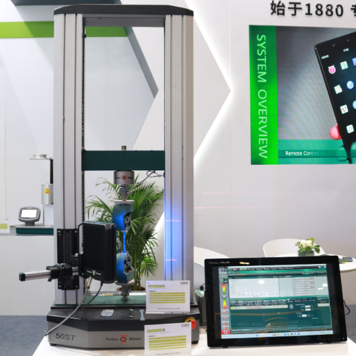
北京柯锐欧科技有限公司为您提供《A fracture-resistant high-entropy alloy for cryogenic applications》,该方案主要用于其他中--检测,参考标准--,《A fracture-resistant high-entropy alloy for cryogenic applications》用到的仪器有深冷试验机 CCCM
推荐专场
相关方案
更多