


方案详情
文
面对世界性的能源危机,作为主要能源的煤炭利用正越来越受到研究者的关注,不管是动力用煤还是工业气化用煤,煤炭的高温熔融粘度都是一个相当重要的指标,而国际上对这方面的研究基本上没有,本文主要讨论煤灰在还原性气体的保护下测量粘度的方法.
方案详情

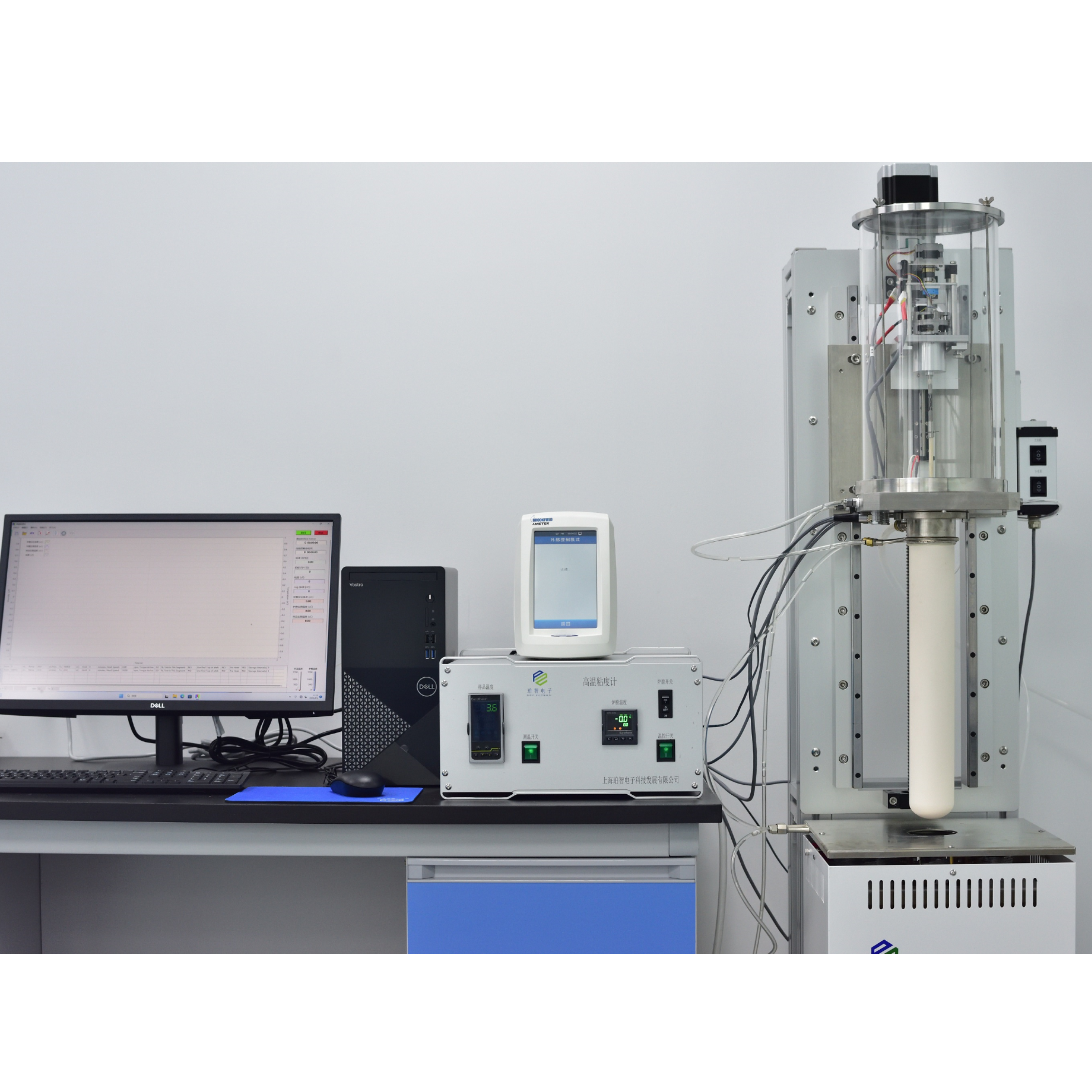
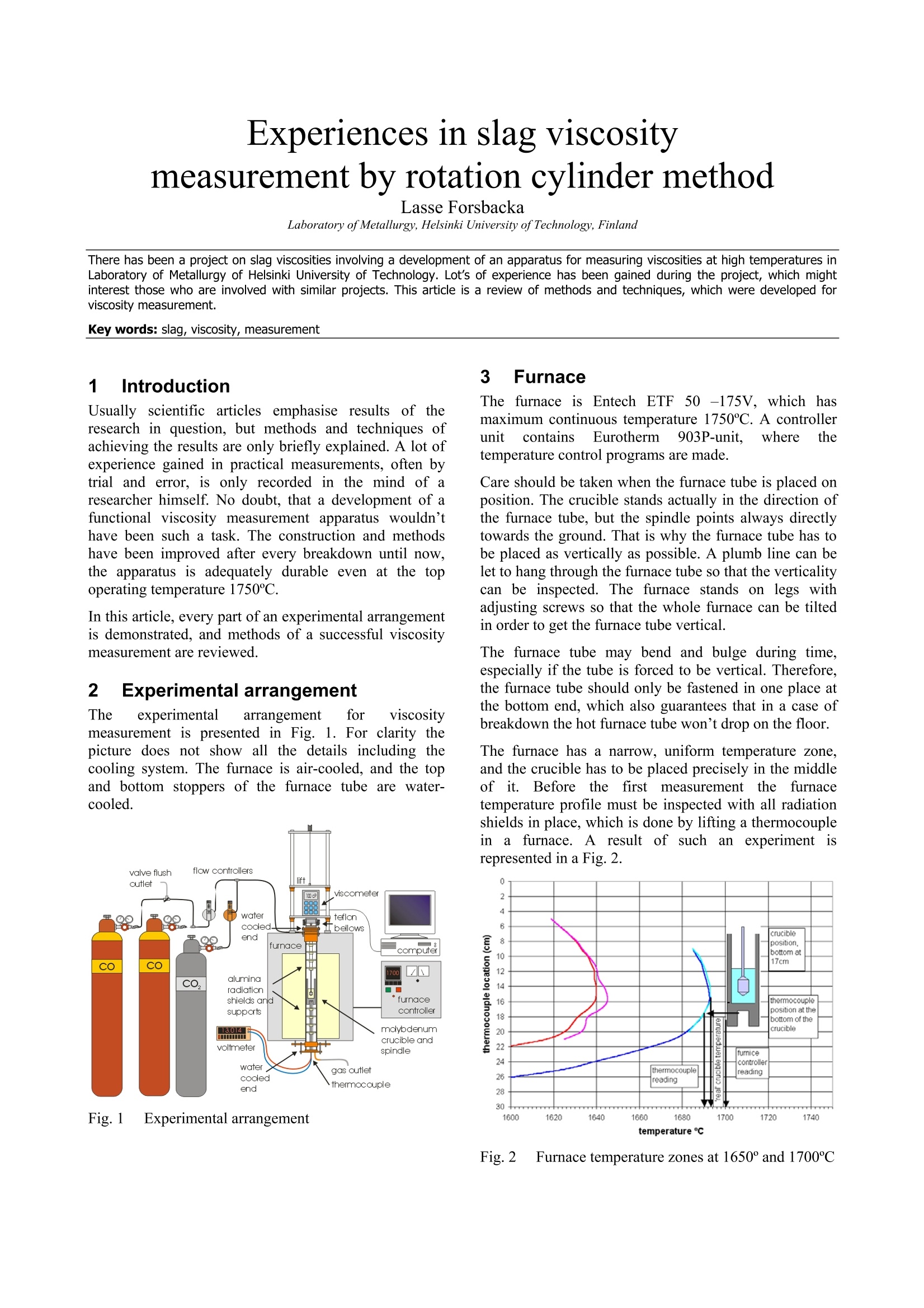
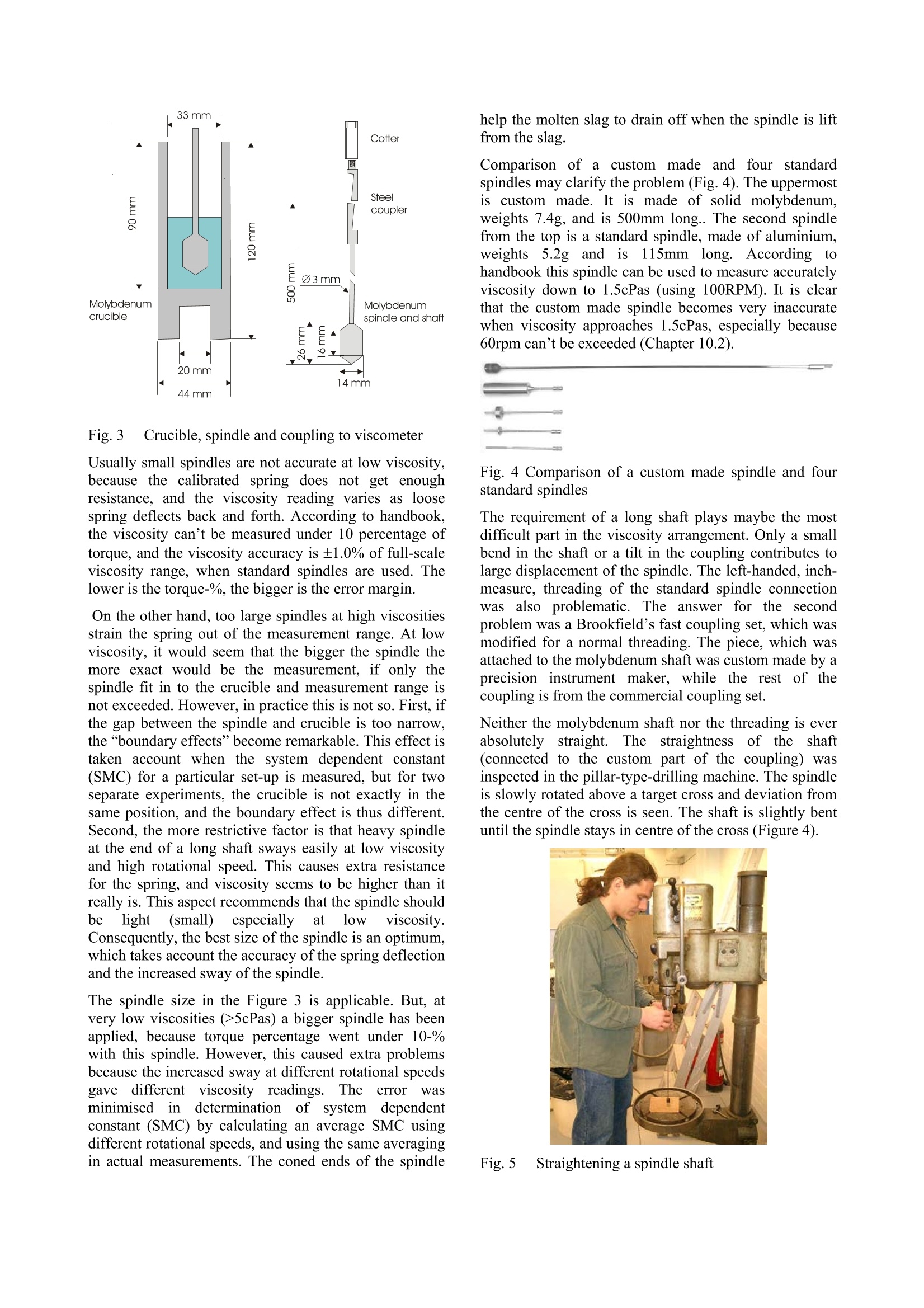
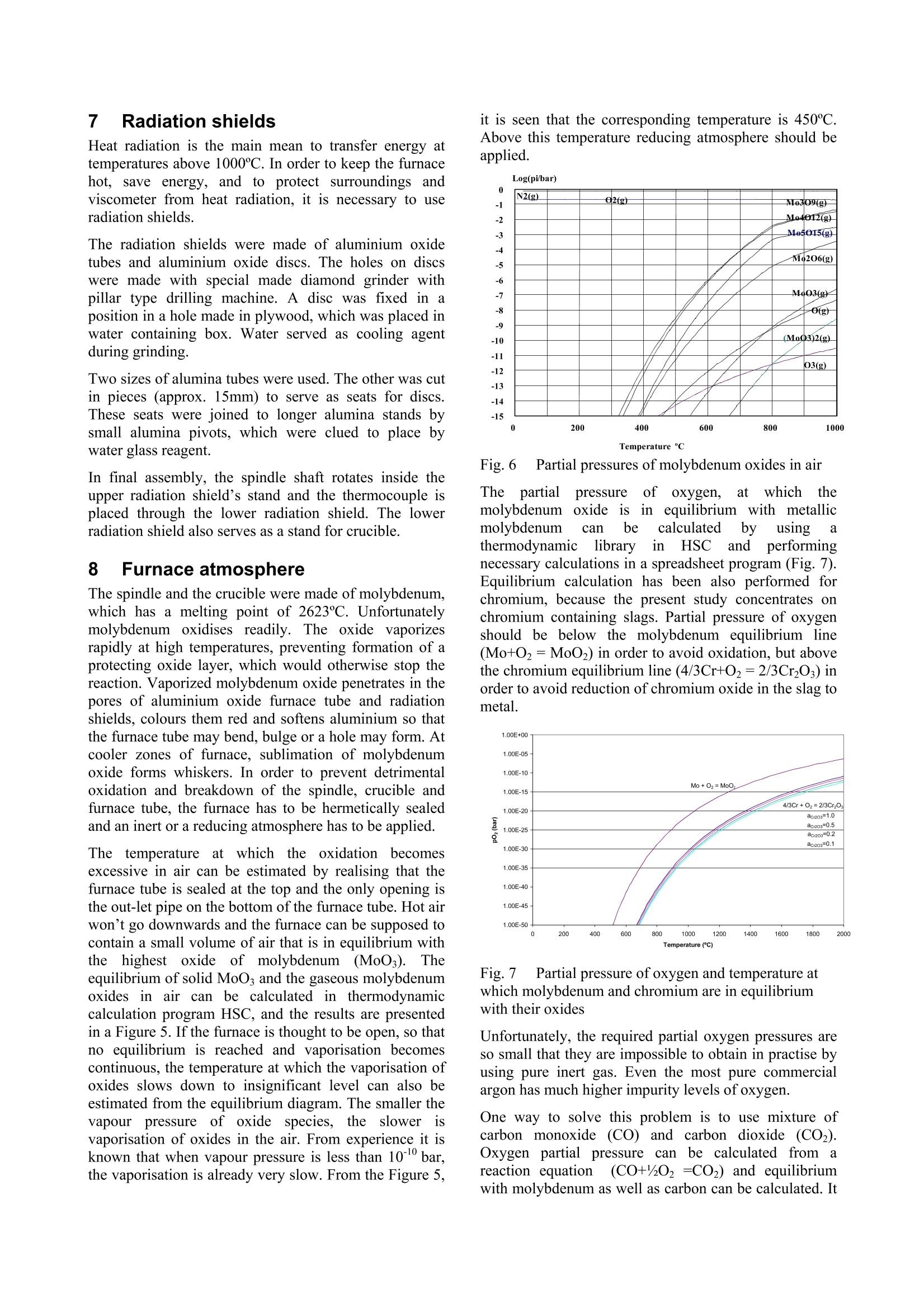
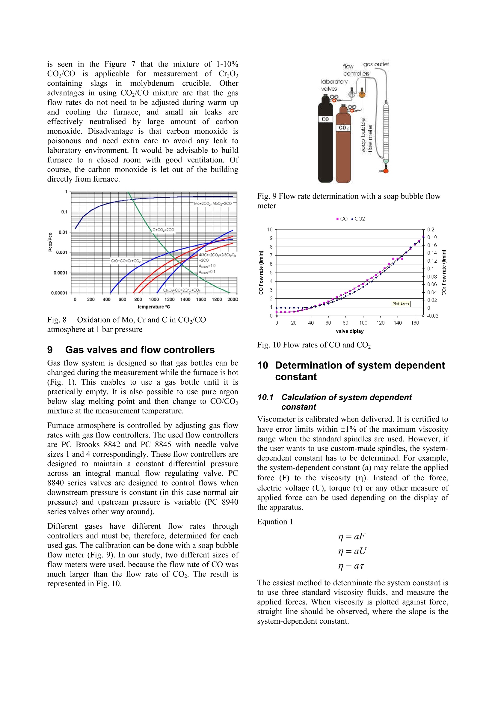
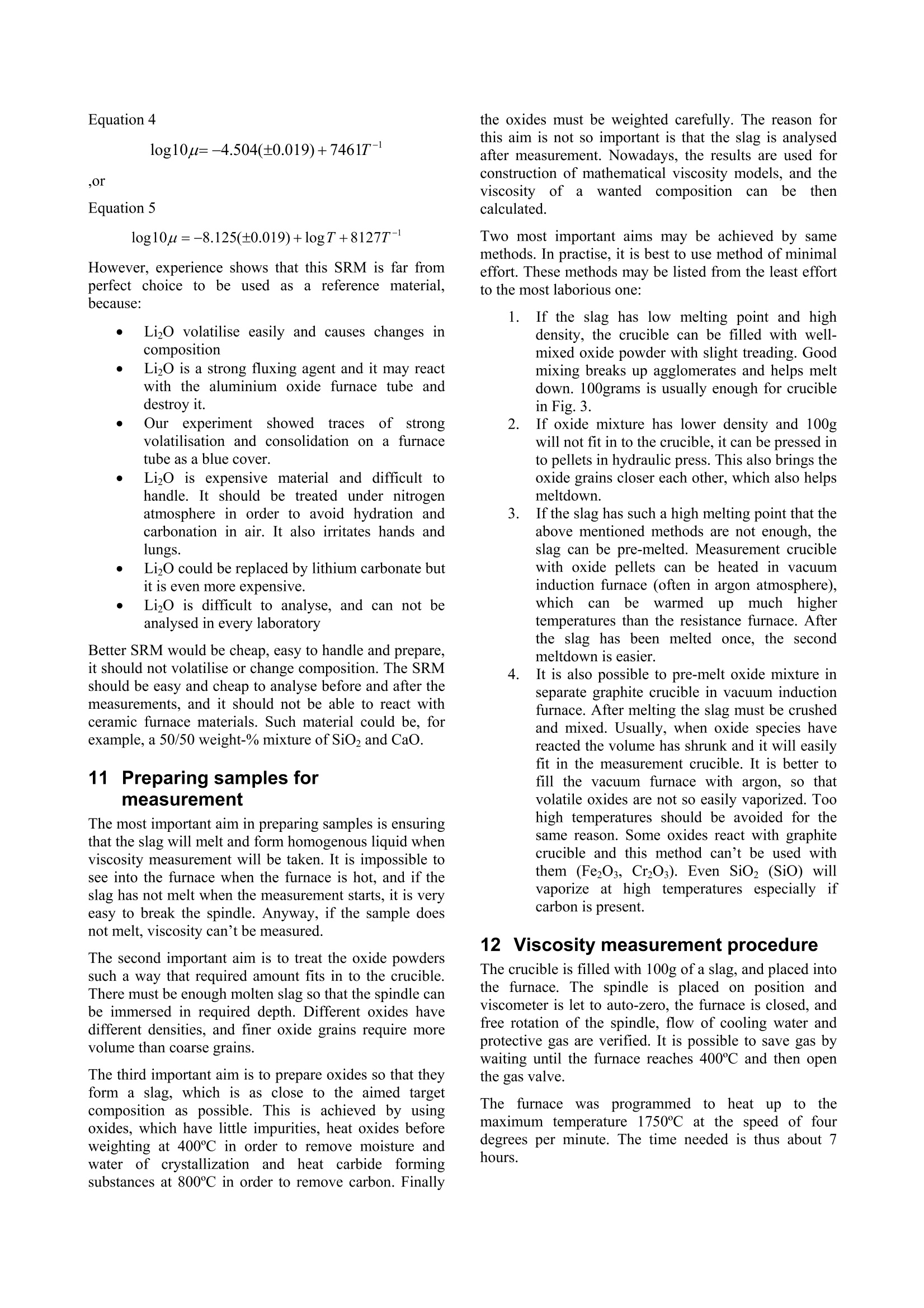
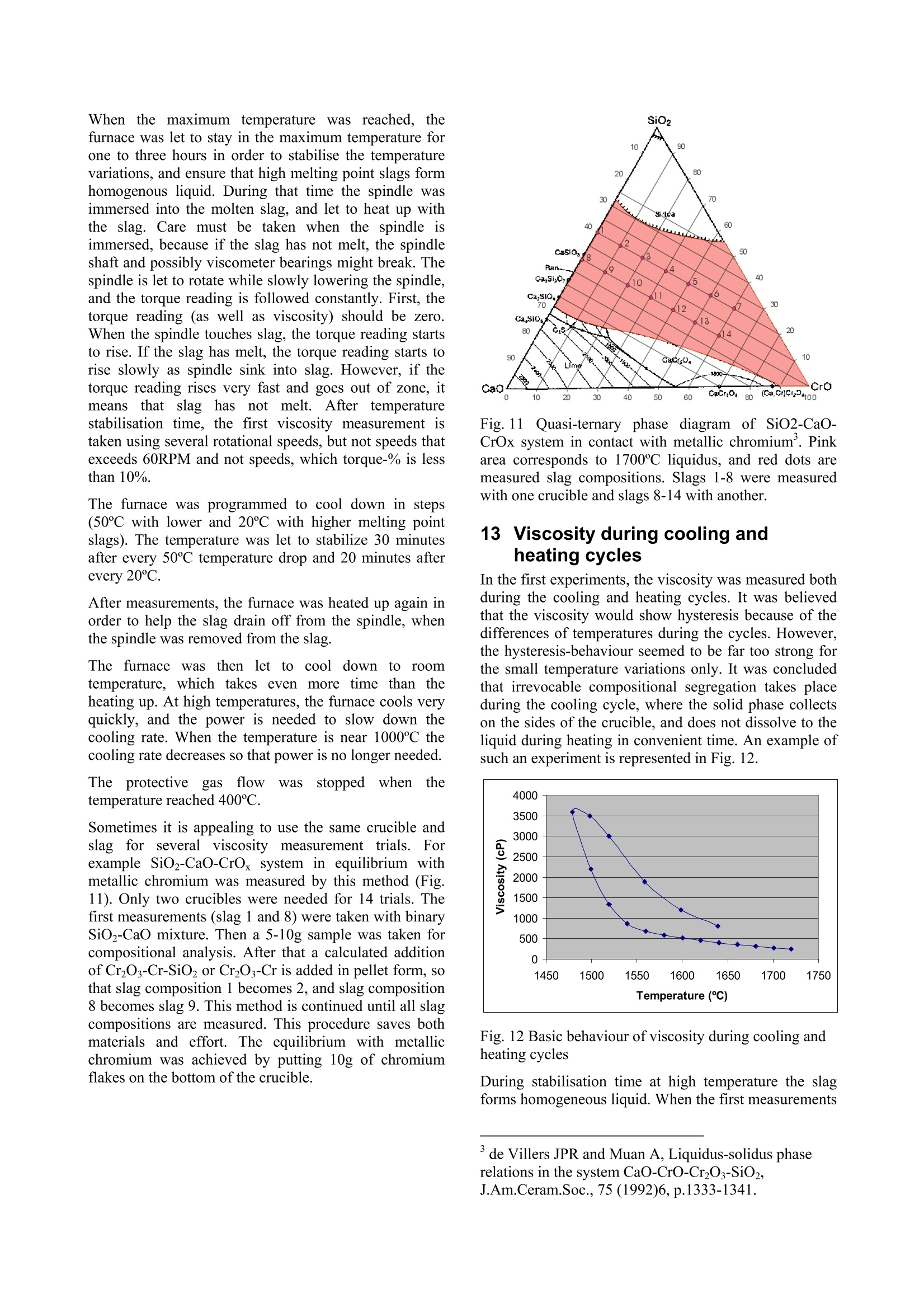
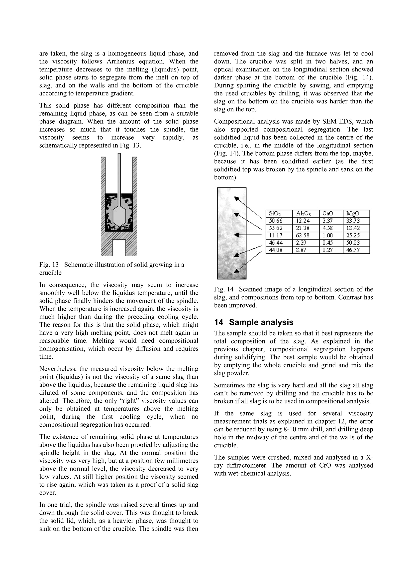
Experiences in slag viscositymeasurement by rotation cylinder method Lasse Forsbacka Laboratory ofMetallurgy, Helsinki University ofTechnology, Finland There has been a project on slag viscosities involving a development of an apparatus for measuring viscosities at high temperatures inLaboratory of Metallurgy of Helsinki University of Technology. Lot’s of experience has been gained during the project, which mightinterest those who are involved with similar projects. This article is a review of methods and techniques, which were developed forviscosity measurement. 1IlIntroduction Usually scientific articles emphasise results of theresearch in question, but methods and techniques ofachieving the results are only briefly explained. A lot ofexperience gained in practical measurements, often bytrial and error, is only recorded in the mind of aresearcher himself. No doubt, that a development of afunctional viscosity measurement apparatus wouldn’thave been such a task. The construction and methodshave been improved after every breakdown until now,the apparatus is adequately durable even at the topoperating temperature 1750℃. In this article, every part of an experimental arrangementis demonstrated, and methods of a successful viscositymeasurement are reviewed. 2 Experimental arrangement The experimental arrangementit for viscositymeasurement is presented in Fig. 1. For clarity thepicture does not show all the details including thecooling system. The furnace is air-cooled, and the topand bottom stoppers of the furnace tube are water-cooled. Fig. 1 Experimental arrangement 3 Furnace The furnace is Entech ETF 50 -175V, which hasmaximum continuous temperature 1750℃. A controllerunitcontains Eurotherm 903P-unit, wheretthetemperature control programs are made. Care should be taken when the furnace tube is placed onposition. The crucible stands actually in the direction ofthe furnace tube, but the spindle points always directlytowards the ground. That is why the furnace tube has tobe placed as vertically as possible. A plumb line can belet to hang through the furnace tube so that the verticalitycan be inspected. The furnace stands on legs withadjusting screws so that the whole furnace can be tiltedin order to get the furnace tube vertical. The furnace tube may bend and bulge during time,especially if the tube is forced to be vertical. Therefore,the furnace tube should only be fastened in one place atthe bottom end, which also guarantees that in a case ofbreakdown the hot furnace tube won’t drop on the floor. The furnace has a narrow, uniform temperature zone,and the crucible has to be placed precisely in the middleof it. Before the first measurement the furnacetemperature profile must be inspected with all radiationshields in place, which is done by lifting a thermocouplein a furnace. A result of such an experiment isrepresented in a Fig. 2. 4 Viscometer The programmable Brookfield LVDV-II+ viscometer isdesigned for measurement of viscosity at a given shearrates. The principle of operation is to drive a spindle,which is immersed in the test fluid, through a calibratedspring. The viscous drag of the fluid against the spindleis measured by the spring deflection, which is detectedwith a rotary transducer. The measurement range is determined by the rotationalspeed of the spindle, the size and shape of the spindle,the container the spindle is rotating in, and the full scaleof rotating spring. The LV in the model type stands forlow viscosity, which means that the viscometer has acalibrated spring that is more supple than in other DV-IImodels. The LV model also comes with the different setof standard spindles. The measuring range of viscosity is 1.5 - 600.000cPaswith the standard spindles, where the lowest viscosity ismeasured with the largest spindle and highest speed, andthe highest viscosity with the smallest spindle and lowestspeed. The user can select from 54 different speeds. Theviscosity accuracy is ±1.0% of full-scale viscosity range.The full scale, or in other words, the maximum viscosityreading at the selected spindle and speed, can bediscovered if the “auto-range” button is pressed any timeduring the measurement. These limits are for thecalibrated spring only. More errors may rise from thespindle construction, temperature measurement, etc. All units can be displayed in SI or CGS units. The basicDV-II unit contains a laboratory stand, set of spindles,temperature probe, guardlleg, carryingcase andconnecting cables. It also contains software for makingprograms to control the viscometer. The viscometer is installed in the lift, which enablesimmersion and removing of the spindle in and out fromthe liquid slag. The viscometer has a level on the topcover for adjusting the apparatus so that the spindlehangs vertically. However, when the standard spindle isreplaced by a custom made spindle with very a longshaft, it is better to use plumb line which is moreaccurate and can also be used for centralizing the spindlein the furnace tube. The procedure is following: Theplumb line is attached to viscometers spindle connection,and the lift is lowered to down position. Then the lift ismoved horizontally so that the plumb line is in the centreof the upper end of the furnace tube. Then, the lower endof the furnace tube is inspected. If the plumb line doesnot lie in the centre, the furnace tube is not vertical.Furnace tube is adjusted by tilting the furnace byadjusting screws in the legs. After the furnace tube isverified to be vertical the viscometer is lifted to highestposition. If the plumb line is moved from the centre ofthe furnace tube, it means that the viscometer is notvertical and neither would the spindle be when installed.Correction is done by adjusting screws under the lift, sothat the plumb line will move back to the centre of thefurnace tube. 5 Software Wingather is an optional Brookfield’s software for MS-Windows, which purpose is to collect data from theviscometer and then save, view, print, plot and analysethis data. The saving format options are the defaultASCII text format (*.dvd), which is compatible withBrookfield’s DVGather software, and Lotus-123 format(*.WKS), which allow it to be imported into mostspreadsheet programs. The imperative feature of this program for the presentwork is that it allows the use of the user-made specialspindles. The system (or spindle) dependent constants“the spindle multiplier constant”(SMC) and “the shearrate constant” (SRC) can be programmed inl Uthecomputer’s memory, after which the software cancalculate a viscosity and a share rate from the torquereading. If Wingather program is not used, the viscositymay be calculated from torque reading, as long as theSMC is known. During the experiments, it was 1found out that theprogram is not very stable, and the data editing is ratherlimited. In consequence,the data was collected manuallyfrom the screen and edited in the MS-Exel. 6 Spindle and crucible The spindle and the crucible were lathed of molybdenumrod. A cross section of the crucible is presented in Fig. 3.The 20mm deep hole in the bottom is made for analumina stand. The container is 90mm deep, which mayseem to be exaggerated. However, when the crucible isfilled with slag powder or pressed slag pellets, it iscompletely full. After melting, the volume of the slag isless than 50% of the powders volume. Because themolybdenum crucibles are expensive, it is tempting totry to clean the used crucibles for re-use. Unfortunately,the solid slag is very difficult to remove from the bottomof the crucibles. It is possible to drill the most of the slagaway with percussion borer, and turn the rest in a lathe,but this requires a lot of effort, and often an extra pair ofa cutter. Because of grain growth at high temperatures,crucibles become brittle, and by time they will crackbecause difference of thermalexpansionbetweenmolybdenum and slag. The size of the spindle has to be such that it is useable inthe wanted viscosity range. Normally, a set of spindlescan be used in viscosity measurement, so that whenviscosity decreases too low for a particular spindle, aarbiggerspindle is replaced.]However.ttlhe hightemperature and the air-tightness of the furnace preventthe change of the spindle during the measurement. Fig. 3 Crucible, spindle and coupling to viscometer Usually small spindles are not accurate at low viscosity,because the calibrated spring does not get enoughresistance, and the viscosity reading varies as loosespring deflects back and forth. According to handbook,the viscosity can’t be measured under 10 percentage oftorque, and the viscosity accuracy is ±1.0% of full-scaleviscosity range, when standard spindles are used. Thelower is the torque-%, the bigger is the error margin. On the other hand, too large spindles at high viscositiesstrain the spring out of the measurement range. At lowviscosity, it would seem that the bigger the spindle themore exact would be the measurement, if only thespindle fit in to the crucible and measurement range isnot exceeded. However, in practice this is not so. First, ifthe gap between the spindle and crucible is too narrow,the “boundary effects”become remarkable. This effect istaken account when the system dependent constant(SMC) for a particular set-up is measured, but for twoseparate experiments, the crucible is not exactly in thesame position, and the boundary effect is thus different.Second, the more restrictive factor is that heavy spindleat the end of a long shaft sways easily at low viscosityand high rotational speed. This causes extra resistancefor the spring, and viscosity seems to be higher than itreally is. This aspect recommends that the spindle shouldbe light(small)especiallyat lowviscosity.Consequently, the best size of the spindle is an optimum,which takes account the accuracy of the spring deflectionand the increased sway of the spindlee. The spindle size in the Figure 3 is applicable. But, atvery low viscosities (>5cPas) a bigger spindle has beenapplied, because torque percentage went under 10-%with this spindle. However, this caused extra problemsbecause the increased sway at different rotational speedsgave differentviscosity readings..Theieeerror wasminimisedirindeterminationofsystem (dependentconstant (SMC) by calculating an average SMC usingdifferent rotational speeds, and using the same averagingin actual measurements. The coned ends of the spindle help the molten slag to drain off when the spindle is liftfrom the slag. Comparison of a custom made and four standardspindles may clarify the problem (Fig. 4). The uppermostis custom made. It is made of solid molybdenum,weights 7.4g, and is 500mm long.. The second spindlefrom the top is a standard spindle, made of aluminium,weights 5.2g and isls. 115mm long. According tohandbook this spindle can be used to measure accuratelyviscosity down to 1.5cPas (using 100RPM). It is clearthat the custom made spindle becomes very inaccuratewhen viscosity approaches 1.5cPas, especially because60rpm can’t be exceeded (Chapter 10.2). 二 Fig. 4 Comparison of a custom made spindle and fourstandard spindles The requirement of a long shaft plays maybe the mostdifficult part in the viscosity arrangement. Only a smallbend in the shaft or a tilt in the coupling contributes tolarge displacement of the spindle. The left-handed, inch-measure, threading of the standard spindle connectionwas also problematic. The answer for the secondproblem was a Brookfield’s fast coupling set, which wasmodified for a normal threading. The piece, which wasattached to the molybdenum shaft was custom made by aprecision instrument maker, while the rest ofthecoupling is from the commercial coupling set. Neither the molybdenum shaft nor the threading is everabsolutely straight. The straightness cof the shaft(connected to the custom part of the coupling) wasinspected in the pillar-type-drilling machine. The spindleis slowly rotated above a target cross and deviation fromthe centre of the cross is seen. The shaft is slightly bentuntil the spindle stays in centre of the cross (Figure4). Fig.5 Straightening a spindle shaft 7 Radiation shields Heat radiation is the main mean to transfer energy attemperatures above 1000℃. In order to keep the furnacehot, save energy, and to protect surroundings andviscometer from heat radiation, it is necessary to useradiation shields. The radiation shields were made of aluminium oxidetubes and aluminium oxide discs. The holes on discswere made with special made diamond grinder withpillar type drilling machine. A disc was fixed in aposition in a hole made in plywood, which was placed inwater containing box. Water served as cooling agentduring grinding. Two sizes of alumina tubes were used. The other was cutin pieces (approx. 15mm) to serve as seats for discs.These seats were joined to longer alumina stands bysmall alumina pivots, which were clued to place bywater glass reagent. In final assembly, the spindle shaft rotates inside theupper radiation shield’s stand and the thermocouple isplaced through the lower radiation shield. The lowerradiation shield also serves as a stand for crucible. 8 Furnace atmosphere The spindle and the crucible were made ofmolybdenum,which has a melting point of 2623℃. Unfortunatelymolybdenum oxidises readily.y. The oxide vaporizesrapidly at high temperatures, preventing formation of aprotecting oxide layer, which would otherwise stop thereaction.Vaporized molybdenum oxide penetrates in thepores of aluminium oxide furnace tube and radiationshields, colours them red and softens aluminium so thatthe furnace tube may bend, bulge or a hole may form. Atcooler zones of furnace, sublimation of molybdenumoxide forms whiskers. In order to prevent detrimentaloxidation and breakdown of the spindle, crucible andfurnace tube, the furnace has to be hermetically sealedand an inert or a reducing atmosphere has to be applied. Thes temperature atwhichthe oxidation becomesexcessive in air can be estimated by realising that thefurnace tube is sealed at the top and the only opening isthe out-let pipe on the bottom of the furnace tube. Hot airwon’t go downwards and the furnace can be supposed tocontain a small volume of air that is in equilibrium withthe highest oxide of molybdenum(MoO3). Theequilibrium of solid MoOs and the gaseous molybdenumoxides in air can be calculated inthermodynamiccalculation program HSC, and the results are presentedin a Figure 5. If the furnace is thought to be open, so thatno equilibrium is reached and vaporisation becomescontinuous, the temperature at which the vaporisation ofoxides slows down to insignificant level can also beestimated from the equilibrium diagram. The smaller thevapour pressure of oxideleSspecies, the slower isvaporisation of oxides in the air. From experience it isknown that when vapour pressure is less than 10-1 bar,the vaporisation is already very slow. From the Figure 5, it is seen that the corresponding temperature is 450℃.Above this temperature reducing atmosphere should beapplied. N2(g) 02(g) M03 Mo4 40yg) 012(g) Mo5 015(g) Mo o206(g) Mg q03(g) O(g (MoQ3)2(g) O3(g) Fig.6 Partial pressures of molybdenum oxides in air The partialpressure of oxygen, at whichtthemolybdenum oxide is in equilibrium with metallicmolybdenum can be calculated by using athermodynamiclibraryiin HSCand performingnecessary calculations in a spreadsheet program (Fig. 7).Equilibrium calculation has been also performed forchromium, because the present study concentrates onchromium containing slags. Partial pressure of oxygenshould be below the molybdenum equilibrium line(Mo+02=MoO2) in order to avoid oxidation, but abovethe chromium equilibrium line (4/3Cr+O2=2/3Cr2O3) inorder to avoid reduction of chromium oxide in the slag tometal. Fig. 7Partial pressure of oxygen and temperature atwhich molybdenum and chromium are in equilibriumwith their oxides Unfortunately, the required partial oxygen pressures areso small that they are impossible to obtain in practise byusing pure inert gas. Even the most pure commercialargon has much higher impurity levels of oxygen. One way to solve this problem is to use mixture ofcarbon monoxide (CO) and carbon dioxide (CO2).Oxygen partial pressure can be calculated from areaction equation (CO+02 =CO2) and equilibriumwith molybdenum as well as carbon can be calculated. It is seen in the Figure 7 that the mixture of 1-10%CO/co1 applicablefor’ measurementof CrzOcontainingslagsinn molybdenumcrucible. (Otheradvantages in using CO2/CO mixture are that the gasflow rates do not need to be adjusted during warm upand cooling thefurnace, andsmall11airleaksareeffectively neutralised1 by large amount of carbonmonoxide. Disadvantage is that carbon monoxide ispoisonous and need extra care to avoid any leak tolaboratory environment. It would be advisable to buildfurnace to a closed room with good ventilation. Ofcourse, the carbon monoxide is let out of the buildingdirectly from furnace. Fig.8 Oxidation of Mo, Cr and C in CO/COatmosphere at 1 bar pressure 9 Gas valves and flow controllers Gas flow system is designed so that gas bottles can bechanged during the measurement while the furnace is hot(Fig. 1). This enables to use a gas bottle until it ispractically empty. It is also possible to use pure argonbelow slag melting point and then change to CO/CO2mixture at the measurement temperature. Furnace atmosphere is controlled by adjusting gas flowrates with gas flow controllers. The used flow controllersare PC Brooks 8842 and PC 8845 with needle valvesizes 1 and 4 correspondingly. These flow controllers aredesigned to maintain a constant differential pressureacross an integral manual flow regulating valve. PC8840 series valves are designed to control flows whendownstream pressure is constant (in this case normal airpressure) and upstream pressure is variable (PC 8940series valves other way around). Different gaseshave different flow rates throughcontrollers and must be, therefore, determined for eachused gas. The calibration can be done with a soap bubbleflow meter (Fig. 9). In our study, two different sizes offlow meters were used, because the flow rate of CO wasmuch larger than the flow rate of CO2. The result isrepresented in Fig. 10. Fig. 9 Flow rate determination with a soap bubble flowmeter mCO+C02 Fig. 10 Flow rates of CO and CO2 10Determination of system dependentconstant 10.1 Calculation of system dependentconstant Viscometer is calibrated when delivered. It is certified tohave error limits within ±1% of the maximum viscosityrange when the standard spindles are used. However, ifthe user wants to use custom-made spindles, the system-dependent constant has to be determined. For example,the system-dependent constant (a) may relate the appliedforce (F) to the viscosity (n). Instead of the force,electric voltage (U), torque (t) or any other measure ofapplied force can be used depending on the display ofthe apparatus. Equation1 n=aF The easiest method to determinate the system constant isto use three standard viscosity fluids, and measure theapplied forces. When viscosity is plotted against force,straight line should be observed, where the slope is thesystem-dependent constant. In the Brookfield's viscometer the constant is called theSpindle Multiplier Constant (SMC), and it is calculatedby a different procedure. At first, the custom-madespindle is immersed into a standard fluid, and the torqueat certain rotational speed is measured. Second, the newfull-scale viscosity range is calculated using Equation 2. Equation 2 Where Rl1jis a new full-scale viscosity range, n isviscosity of a standard fluid and Y is the torque-%reading at the selected rotations per minute. (Theaccuracy of calibrated spring is ±1% of the R1). The SMC is then Equation 3 Where the rpm is rotations per minute and TK is a torqueconstant, which is obtainable from the Brookfield’sviscometer manual, and is 0.09379 for LVDV-II+viscometer. 10.2Determination of system constant at roomtemperature In principle only one measurement with one standardfluid and one rotational speed would be sufficient fordetermine an apparatus constant. However, it is better touse more standard fluids covering wider viscosity range,and several rotational speeds. This way the validity ofthieeapparatus constant at different viscosities androtational speeds can be checked. For example, the longshaft of the spindle may cause oscillations at highrotational speeds, and thus more resistance for spindlerotations. Therefore, the corresponding SMC valuemight be different for low and high speeds. If thedifference is great, the spindle construction has to beimproved or the shaft has to be straightened. The SMC constant can be selected so that it bestrepresent true viscosity of the slag, e.g. a different SMCmay be used in different viscosity ranges, an averageSMC may be used, or if SMC shows linear variation, anregression formula might be considered. In any case, thestandard fluids should be selected so that they haveapproximately same viscosities that the slag to bemeasured. In the present study three silicon oils with nominalviscosities of 10, 50, and 500cPas (100, 500, 5000cP) at25℃ served as standard fluids. In order to keep thetemperature at exact 25℃ during measurement, thecrucible, half filled with silicon oil, was placed in awater bath (Haake DC30) and the temperature was let tosettle before measurement. The spindle construction represented in Figure 3, gavelittle variation in SMC determination with these standardoils. At lower viscositiess (>5cPas) thisspindleconstruction gives too little resistance to be exact inmeasurements. Usually, the most accurate viscosity reading is obtainedwhen the torque-% reading (and the speed of the spindle)is highest possible. In practice this not always true,because the highest possible torque-% reading mayrequire excessive high speeds of the spindle, whichcauses increased resistance due oscillation, as explainedbefore. Therefore, during determination of SMC, andalso during actual experiments the highest applied speedwas 60rpm, and when 60rpm was too much, the speedwas decreased, so that the highest possible speed wasused. 10.3 Determination of system constant at hightemperature with SRM At high temperature the system dependent constant isobviously slightly different than in room temperature,because the crucible and the spindle expands. It has beenrecommended to determinate the system dependentconstant also at high temperature. A high temperature standard reference material (SRM)has been developed in BCR program of the EU. Thecomposition of this material is 19.46% LizO, 14.06Al2O3 and 63.8% SiO2. It was recommended thatviscosity measurements should be repeated on the SRMaccording to a strict protocol in an attempt to reduce thescatter shown by the results: The sample should be dried overnight at 110°℃before measurements -Molybdenum or platinum components werepreferable to graphite -A neutral (N2, Ar) or reducing (Ar+10%H2)atmosphere should be provided -Samples (SRM) should not be heated above1400°C -All thermocouples should be checked againstcalibrated thermocouples -The difference between TmeltandTmeasuredshould be determined -Nature of the isothermal hot zone should bewell known -Before measurements on the SRM slag theviscometer should be calibrated with at leasttwo oils in the 0.1-1.0 Pas (100cP-1000cP)fangeaswell asNBS710glass athightemperature The following temperature-viscosity relationships arerecommended for SRM: ( Broadbent CP, Franken M, Gould MD, Mills KC. 4" International Conference on Molten Slags, Fluxes and Salts, Japan, 1 992. ) ,or Equation 5 However, experience shows that this SRM is far fromperfect choice to be used as a reference material.because: ● LizO volatilise easily and causes changes incomposition LizO is a strong fluxing agent and it may reactwith the aluminium oxide furnace tube anddestroy it. Our experimentSshowedtracesof strongvolatilisation and consolidation on a furnacetube as a blue cover. LizO is expensive material and difficult tohandle. It should be treated under nitrogenatmosphere in order to avoid hydration andcarbonation in air. It also irritates hands andlungs. LizO could be replaced by lithium carbonate butit is even more expensive. LizO is difficult to analyse, and can not beanalysed in every laboratory Better SRM would be cheap, easy to handle and prepare,it should not volatilise or change composition. The SRMshould be easy and cheap to analyse before and after themeasurements, and it should not be able to react withceramic furnace materials. Such material could be, forexample, a 50/50 weight-%mixture of SiO2 and CaO. 111 FPreparing samples formeasurement The most important aim in preparing samples is ensuringthat the slag will melt and form homogenous liquid whenviscosity measurement will be taken. It is impossible tosee into the furnace when the furnace is hot, and if theslag has not melt when the measurement starts, it is veryeasy to break the spindle. Anyway, if the sample doesnot melt, viscosity can’t be measured. The second important aim is to treat the oxide powderssuch a way that required amount fits in to the crucible.There must be enough molten slag so that the spindle canbe immersed in required depth. Different oxides havedifferent densities, and finer oxide grains require morevolume than coarse grains. The third important aim is to prepare oxides so that theyform a slag, which is as close to the aimed targetcomposition as possible. This is achieved by usingoxides, which have little impurities, heat oxides beforeweighting at 400℃ in order to remove moisture andwater of crystallization andheat carbide formingsubstances at 800℃ in order to remove carbon. Finally the oxides must be weighted carefully. The reason forthis aim is not so important is that the slag is analysedafter measurement. Nowadays, the results are used forconstruction of mathematical viscosity models, and theviscosity offa wantedl compositioncan be thencalculated. Two most important aims may be achieved by samemethods. In practise, it is best to use method of minimaleffort. These methods may be listed from the least effortto the most laborious one: l.If the slag has low melting point and highdensity, the crucible can be filled with well-mixed oxide powder with slight treading. Goodmixing breaks up agglomerates and helps meltdown. 100grams is usually enough for cruciblein Fig. 3. 2. If oxide mixture has lower density and 100gwill not fit in to the crucible, it can be pressed into pellets in hydraulic press. This also brings theoxide grains closer each other, which also helpsmeltdown. 3. If the slag has such a high melting point that theabove mentioned methods are not enough, theslag can be pre-melted. Measurement cruciblewith oxide pellets can be heated in vacuuminduction furnace (often in argon atmosphere),whichh canbe warmedup much hhighertemperatures than the resistance furnace. Afterthe slag has been melted once, the secondmeltdown is easier. 4. It is also possible to pre-melt oxide mixture inseparate graphite crucible in vacuum inductionfurnace. After melting the slag must be crushedand mixed. Usually, when oxide species havereacted the volume has shrunk and it will easilyfit in the measurement crucible. It is better tofill the vacuum furnace with argon, so thatvolatile oxides are not so easily vaporized. Toohigh temperatures should be avoided for thesame reason. Some oxides react with graphitecrucible and this method can’t be used withthem (Fe203, Cr203). Even SiO2 (SiO) willvaporize at high temperatures especially ifcarbon is present. 12Viscosity measurement procedure The crucible is filled with 100g of a slag, and placed intothe furnace. The spindle is placed on position andviscometer is let to auto-zero, the furnace is closed, andfree rotation of the spindle, flow of cooling water andprotective gas are verified. It is possible to save gas bywaiting until the furnace reaches 400℃ and then openthe gas valve. The furnacee wasasprogrammed to heat up to themaximum temperature 1750℃ at the speed of fourdegrees per minute. The time needed is thus about 7hours. When the maximum temperature was reached, thefurnace was let to stay in the maximum temperature forone to three hours in order to stabilise the temperaturevariations, and ensure that high melting point slags formhomogenous liquid. During that time the spindle wasimmersed into the molten slag, and let to heat up withthe slag. Care must be taken when the spindle isimmersed, because ifthe slag has not melt, the spindleshaft and possibly viscometer bearings might break. Thespindle is let to rotate while slowly lowering the spindle,and the torque reading is followed constantly. First, thetorque reading (as well as viscosity) should be zero.When the spindle touches slag, the torque reading startsto rise. If the slag has melt, the torque reading starts torise slowly as spindle sink into slag. However, if thetorque reading rises very fast and goes out of zone, itmeanstthattislag has not melt. After temperaturestabilisation time, the first viscosity measurement istaken using several rotational speeds, but not speeds thatexceeds 60RPM and not speeds, which torque-% is lessthan 10%. The furnace was programmed to cool down in steps(50℃ with lower and 20℃ with higher melting pointslags). The temperature was let to stabilize 30 minutesafter every 50℃ temperature drop and 20 minutes afterevery 20℃. After measurements, the furnace was heated up again inorder to help the slag drain off from the spindle, whenthe spindle was removed from the slag. The furnace was then let to cool down to roomtemperature, which takes even more time than theheating up. At high temperatures, the furnace cools veryquickly, and the power is needed to slow down thecooling rate. When the temperature is near 1000℃ thecooling rate decreases so that power is no longer needed. Theprotectiveggas flow was stoppedwhenn thetemperature reached 400℃. Sometimes it is appealing to use the same crucible andslag for severalviscosity measurementttrials.s.Forexample SiO2-CaO-CrOx system in equilibrium withmetallic chromium was measured by this method (Fig.11). Only two crucibles were needed for 14 trials. Thefirst measurements (slag 1 and 8) were taken with binarySiO2-CaO mixture. Then a 5-10g sample was taken forcompositional analysis. After that a calculated additionof Cr2O3-Cr-SiO or Cr2O3-Cr is added in pellet form, sothat slag composition 1 becomes 2, and slag composition8 becomes slag 9. This method is continued until all slagcompositions are measured. This procedure saves bothmaterials and effort. The equilibrium with metallicchromium was achieved by putting 10g of chromiumflakes on the bottom of the crucible. Fig. 11 Quasi-ternary phase diagram of SiO2-CaO-CrOx system in contact with metallic chromium’. Pinkarea corresponds to 1700C liquidus, and red dots aremeasured slag compositions. Slags 1-8 were measuredwith one crucible and slags 8-14 with another. 133Viscosity during cooling andheating cycles In the first experiments, the viscosity was measured bothduring the cooling and heating cycles. It was believedthat the viscosity would show hysteresis because of thedifferences of temperatures during the cycles. However,the hysteresis-behaviour seemed to be far too strong forthe small temperature variations only. It was concludedthat irrevocable compositional segregation takes placeduring the cooling cycle, where the solid phase collectson the sides of the crucible, and does not dissolve to theliquid during heating in convenient time. An example ofsuch an experiment is represented in Fig. 12. Fig. 12 Basic behaviour of viscosity during cooling andheating cycles During stabilisation time at high temperature the slagforms homogeneous liquid. When the first measurements ( ’de V illers JPR and Muan A, Liquidus-solidus phaserelations in the system CaO-CrO-Cr2O3-SiO2,J.Am.Ceram.Soc., 75 (1992)6, p.1333-1341. ) are taken, the slag is a homogeneous liquid phase, andthe viscosity follows Arrhenius equation. When thetemperature decreases to the melting (liquidus) point,solid phase starts to segregate from the melt on top ofslag, and on the walls and the bottom of the crucibleaccording to temperature gradient. This solid phase has different composition than theremaining liquid phase, as can be seen from a suitablephase diagram. When the amount of the solid phaseincreases so much that it touches the spindle, theviscosityy seems toincrease very rapidly, asschematically represented in Fig. 13. Fig. 13 Schematic illustration of solid growing in acrucible In consequence, the viscosity may seem to increasesmoothly well below the liquidus temperature, until thesolid phase finally hinders the movement of the spindle.When the temperature is increased again, the viscosity ismuch higher than during the preceding cooling cycle.The reason for this is that the solid phase, which mighthave a very high melting point, does not melt again inreasonable time. Melting would need compositionalhomogenisation, which occur by diffusion and requirestime. Nevertheless, the measured viscosity below the meltingpoint (liquidus) is not the viscosity of a same slag thanabove the liquidus, because the remaining liquid slag hasdiluted of some components, and the composition hasaltered. Therefore, the only “right”viscosity values canonly be obtained at temperatures above the meltingpoint, duringthefirst: cooling, (cycle,when nocompositional segregation has occurred. The existence of remaining solid phase at temperaturesabove the liquidus has also been proofed by adjusting thespindle height in the slag. At the normal position theviscosity was very high, but at a position few millimetresabove the normal level, the viscosity decreased to verylow values. At still higher position the viscosity seemedto rise again, which was taken as a proof of a solid slagcover. In one trial, the spindle was raised several times up anddown through the solid cover. This was thought to breakthe solid lid, which, as a heavier phase, was thought tosink on the bottom of the crucible. The spindle was then removed from the slag and the furnace was let to cooldown. The crucible was split in two halves, and anoptical examination on the longitudinal section showeddarker phase at the bottom of the crucible (Fig. 14).During splitting the crucible by sawing, and emptyingthe used crucibles by drilling, it was observed that theslag on the bottom on the crucible was harder than theslag on the top. Compositional analysis was made by SEM-EDS, whichalso supported compositional segregation. The lastsolidified liquid has been collected in the centre of thecrucible, i.e., in the middle of the longitudinal section(Fig. 14). The bottom phase differs from the top, maybe,because it has been solidified earlier (as the firstsolidified top was broken by the spindle and sank on thebottom). SiO A103 CaO MgO 50.66 12.24 3.37 33.73 55.62 21.38 4.58 18.42 11.17 62.58 1.00 25.25 46.44 2.29 0.45 50.83 44.08 8.87 0.27 46.77 Fig. 14 Scanned image of a longitudinal section of theslag, and compositions from top to bottom. Contrast hasbeen improved. 14Sample analysis The sample should be taken so that it best represents thetotal composition of the slag. As explained in theprevious chapter, compositional segregation happensduring solidifying. The best sample would be obtainedby emptying the whole crucible and grind and mix theslag powder. Sometimes the slag is very hard and all the slag all slagcan’t be removed by drilling and the crucible has to bebroken if all slag is to be used in compositional analysis. Iffthe sameslag is useddfor)r severalviscositymeasurement trials as explained in chapter 12, the errorcan be reduced by using 8-10 mm drill,and drilling deephole in the midway of the centre and of the walls of thecrucible. The samples were crushed, mixed and analysed in a X-ray diffractometer. The amount of CrO was analysedwith wet-chemical analysis.
确定


还剩7页未读,是否继续阅读?


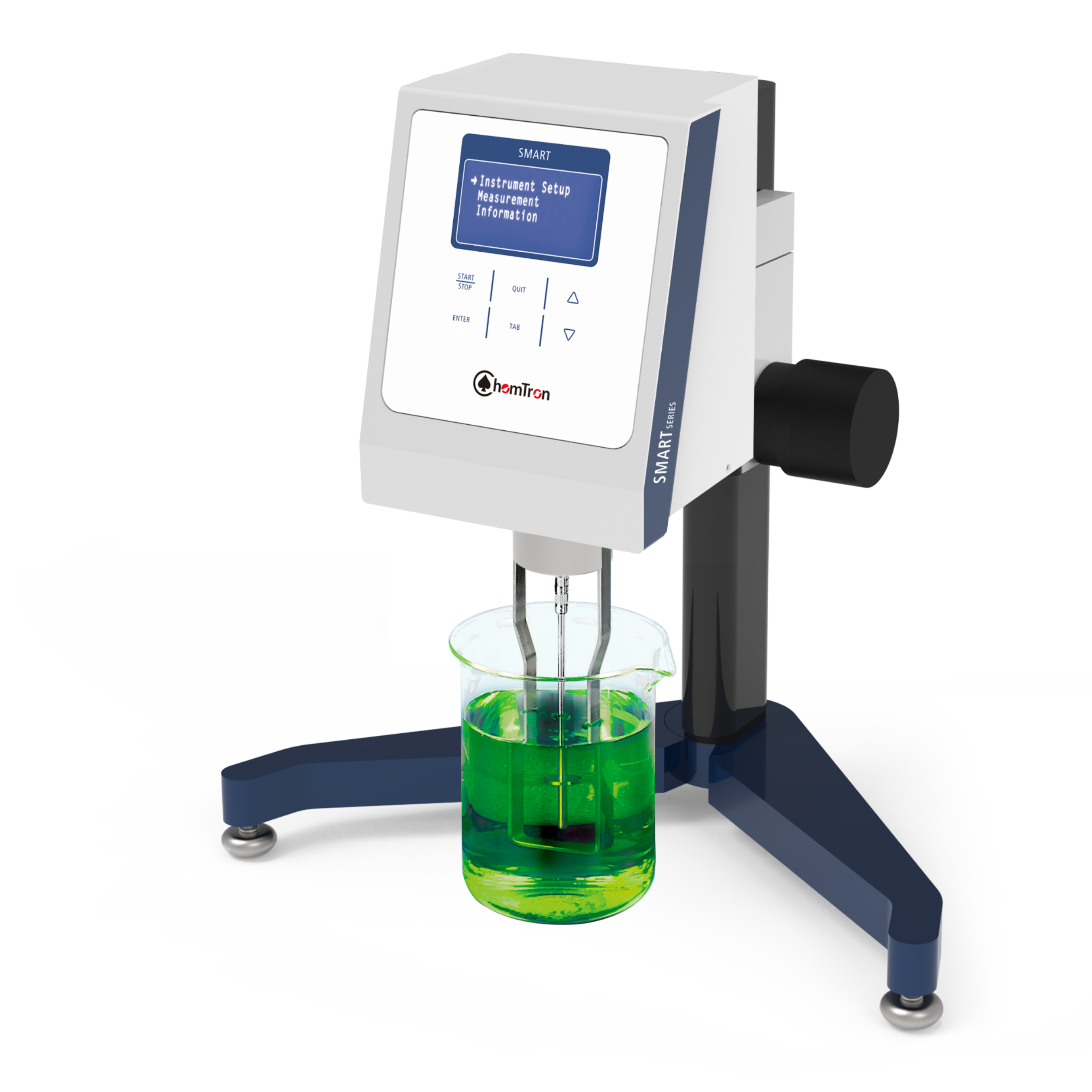
上海珀智电子科技发展有限公司为您提供《煤灰中高温粘度分析检测方案(粘度计)》,该方案主要用于煤炭中高温粘度分析检测,参考标准--,《煤灰中高温粘度分析检测方案(粘度计)》用到的仪器有高温粘度计
推荐专场

相关方案
更多