


方案详情
文
本文摘自意大利国家计量院ISTITUTO NAZIONALE DI RICERCA METROLOGICA(INRiM)在2013年发布的年度报告。文中主要介绍了校准建筑节能监测用热流计的参考装置,以及装置的设计和热流计校准过程。通过此热流计校准的参考装置以实现热流计校准的规范性和标准化。
方案详情

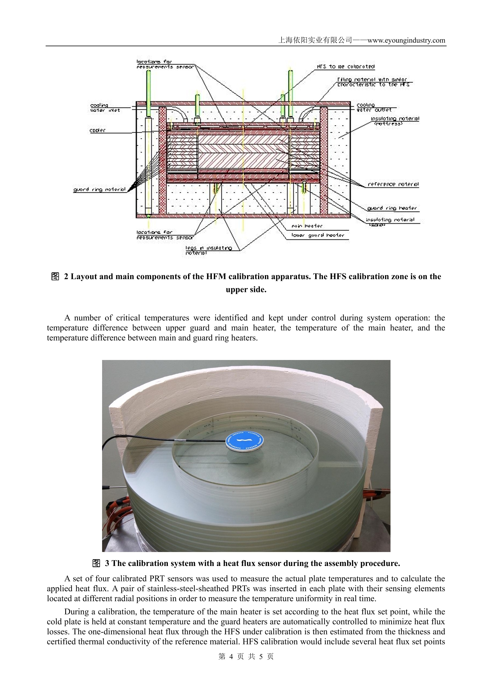
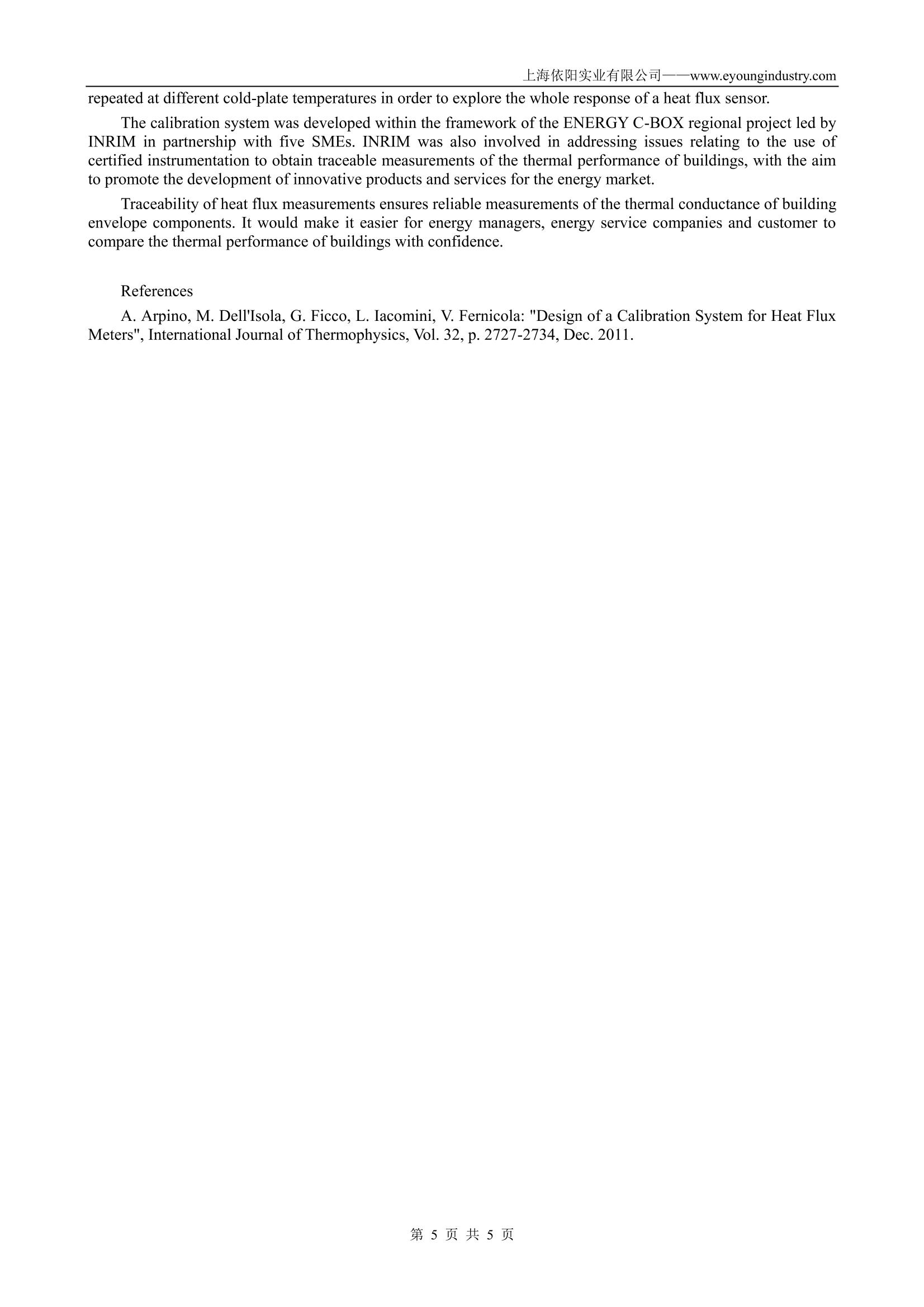
上海依阳实业有限公司- -www.eyoungindustry.com 校准建筑节能监测用热流计的参考装置 上海依阳实业有限公司 www.eyoungindustry.com 摘要:本文摘自意大利国家计量院 ISTITUTO NAZIONALE DI RICERCA METROLOGICA (INRiM)在2013年发布的年度报告。文中主要介绍了校准建筑节能监测用热流计的参考装置,,以及装置的设计和热流计校准过程。通过此热流计校准的参考装置以实现热流计计准的规范性和标准化。 A Reference System for Heat Flux Sensor Calibration Applicationto the Thermal Conductance of Buildings Improvements in the energy efficiency of buildings are called upon by European directives, such as directive2002/91/CE, which sets the maximum values of energy needs and thermal transmittance of building envelopecomponents. The importance of the latter parameter is recognized both by Italian law (DM 2 April 1998,Legislative Decree no. 115 of 30 May 2008, Min. Degree of 11 March 2008) and by building sustainabilitycertification systems (LEED, ITACA, etc.). In situ measurements of envelope components are needed forestimating the thermal transmittance of existing buildings in order to perform the energy certification and tovalidate the energy performance design of new buildings. When design data are not available, the thermaltransmittance of existing buildings can be measured in situ, according to ISO 9869, by means of a heat flux meter(HFM). HFMs provide an indirect measurement of heat fluxes through a wall (or a material specimen) by means of aone-dimensionalheat flux sensor(HFS) and severaltemperature sensors(thermocouples or resistancethermometers), which provide an estimate of the temperature gradient across the building component underinvestigation. The wall thermal conductance (or transmittance) is then evaluated by post-processing the acquireddata. An HFS is basically made of a thin plate of insulating material sandwiched in a thermopile (i.e., a connectionin series of many differential thermocouples), which gives the temperature difference across the plate itself. Whena heat flux crosses the HFS, the insulating material offers a known thermal resistance and, as a consequence, atemperature gradient builds up. The temperature difference across the plate is proportional to the heat flux andplate thickness and inversely proportional to its thermal conductivity. Even though in the recent years, several studies have been conducted to investigate the metrologicalperformance of HFMs and the associated calibration procedures, the devices employed in building applicationsare often uncalibrated and, consequently, measurement traceability cannot be guaranteed. This poor practice isprobably due both to the intrinsic technical complexity of the measurement chain and to a lack of suitablereference standards even at NMI level. In collaboration with UNICLAM, INRIM designed a new referencesystem for HFM calibration. A thorough numerical investigation of the system was carried out in order to evaluate its metrologicalperformance and potential application as a calibration standard. This apparatus, figure 1, based on a Guarded Hot Plate approach is designed to generate a knownone-dimensional heat flux, in such a way that the relationship between the HFS output and the applied heat fluxcan be determined. The system presents an axial symmetry and is designed with an additional thermal guard inorder to prevent heat dispersion in the upper section ("Cc"), thus ensuring that the heat flux generated by the mainheater flows through the measuring section ("Oo"). Furthermore, a coaxial thermal guard and thick insulationmaterial are used to ensure that the heat flux through the device under calibration is one-dimensional. Theworking temperature of the HFM can be varied by acting on the cold plate ("QOPR") whose temperature iscontrolled by a fluid-flow cooling system. A stack of up to three borosilicate glass plates of certified thermalconductivity coefficient (BCR-039) is inserted between the hot plate ("Ee") and the measuringF seection ("Oo") toestimate the heat flux from the temperature drop across the borosilicate glass plates (sections "Ee" and "Mm"). The design of the apparatus is flexible enough to be used in different applications such as the measurement ofthe thermal conductivity of insulating materials by generation of a known heat flux and HFM calibration by an absolute method (i.e., by measuring the power generated by the main heater) or by a relative method (i.e., bymeasuring the temperature drop across the reference material). 303.0 图 1 Results of numerical investigation on temperature distribution and the vertical heat flux and itsdistribution as a function of the radial position, with a heat flux of 10 W m-2 (on the left) and 100 Wm-2(on the right). The HFS calibration zone is on the lower side. The metrological performance of the calibration system was preliminarily checked by a numericalinvestigation employing a commercial Finite Element Code. The results showed that in order to minimize the uncertainty of the generated heat flux, a very finetemperature control on the thermal guard is needed: in the worst case, at low heat fluxes, a temperature change of0.01 K in the upper thermal guard causes a non uniformity of the heat flux of about 0.4 %. On the basis of the numerical investigation, a HFM calibration apparatus was designed and built. To make the measurement zone easily accessible and reduce installation time before calibration, the systemwas turned upside down (figure 1 and 2) with respect of the initial design. Because of that, the air gap whichdecouples the heaters was replaced with a solid insulator. The system also rests on three legs of insulating materialto further minimize heat losses. The aluminum plates used to uniform the heat flux also accommodate a flat heaterand the control sensor. A passive coaxial guard ring made of borosilicate glass was added to minimize the radialdispersion of heat around the reference plates in order to exploit the whole calibration area. In this way, thecalibration cross section corresponds to a circle 300 mm in diameter. The borosilicate glass stack is made of threeplates having different thickness, which can be used alone or combined to widen the heat flux range. Thetemperature control and homogeneity of the brass cold plate was achieved by milling several channels in the plate,sealing them with a lid and connecting the resulting fluid circuit to an external temperature bath. 图 2 Layout and main components of the HFM calibration apparatus. The HFS calibration zone is on theupper side. A number of critical temperatures were identified and kept under control during system operation: thetemperature difference between upper guard and main heater, the temperature of the main heater, and thetemperature difference between main and guard ring heaters. 图 3The calibration system with a heat flux sensor during the assembly procedure. A set of four calibrated PRT sensors was used to measure the actua plate temperatures and to calculate theapplied heat flux. A pair of stainless-steel-sheathed PRTs was inserted in each plate with their sensing elementslocated at different radial positions in order to measure the temperature uniformity in real time. During a calibration, the temperature of the main heater is set according to the heat flux set point, while thecold plate is held at constant temperature and the guard heaters are automatically controlled to minimize heat fluxlosses. The one-dimensional heat flux through the HFS under calibration is then estimated from the thickness andcertified thermal conductivity of the reference material. HFS calibration would include several heat flux set points repeated at different cold-plate temperatures in order to explore the whole response of a heat flux sensor. The calibration system was developed within the framework of the ENERGY C-BOX regional project led byINRIM in partnership with five SMEs. INRIM was also involved in addressing issues relating to the use ofcertified instrumentation to obtain traceable measurements of the thermal performance of buildings, with the aimto promote the development of innovative products and services for the energy market. Traceability of heat flux measurements ensures reliable measurements of the thermal conductance of buildingenvelope components. It would make it easier for energy managers, energy service companies and customer tocompare the thermal performance of buildings with confidence. References A. Arpino, M. Dell'Isola, G. Ficco, L. Iacomini, V. Fernicola: "Design of a Calibration System for Heat FluxMeters", International Journal of Thermophysics, Vol. 32, p. 2727-2734,Dec. 2011. 第页共页
确定


还剩3页未读,是否继续阅读?

产品配置单
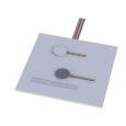
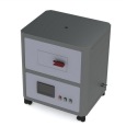
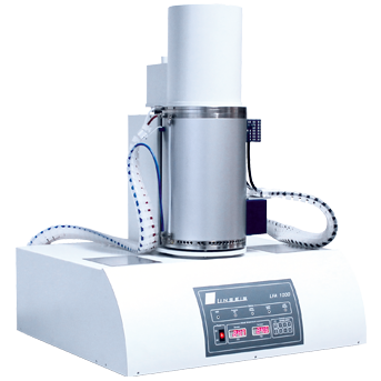
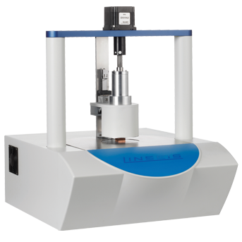
上海依阳实业有限公司为您提供《校准建筑节能监测用热流计的参考装置》,该方案主要用于建筑工程中检测,参考标准--,《校准建筑节能监测用热流计的参考装置》用到的仪器有高灵敏度热阻式热流计、稳态护热板法导热系数测定仪
推荐专场
相关方案
更多
该厂商其他方案
更多