


方案详情
文
标准集团(香港)有限公司技术部为您介绍橡胶回弹性测试仪的集中测试方法。橡胶回弹性测试的方法和标准应该根据用户实际需求来确定。我公司橡胶回弹性测试仪技术资料齐全,欢迎免费咨询交流021-64208466.
方案详情

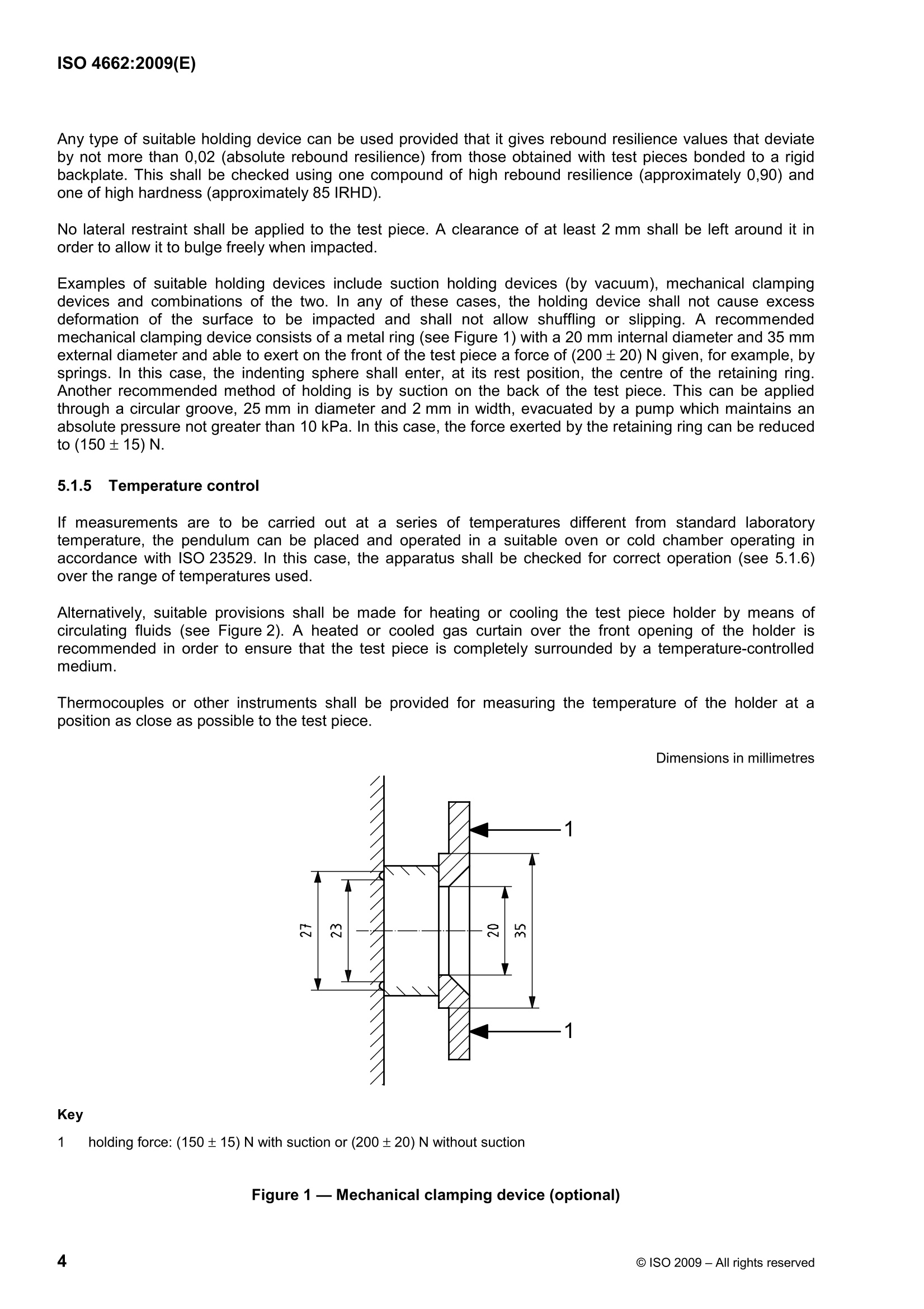
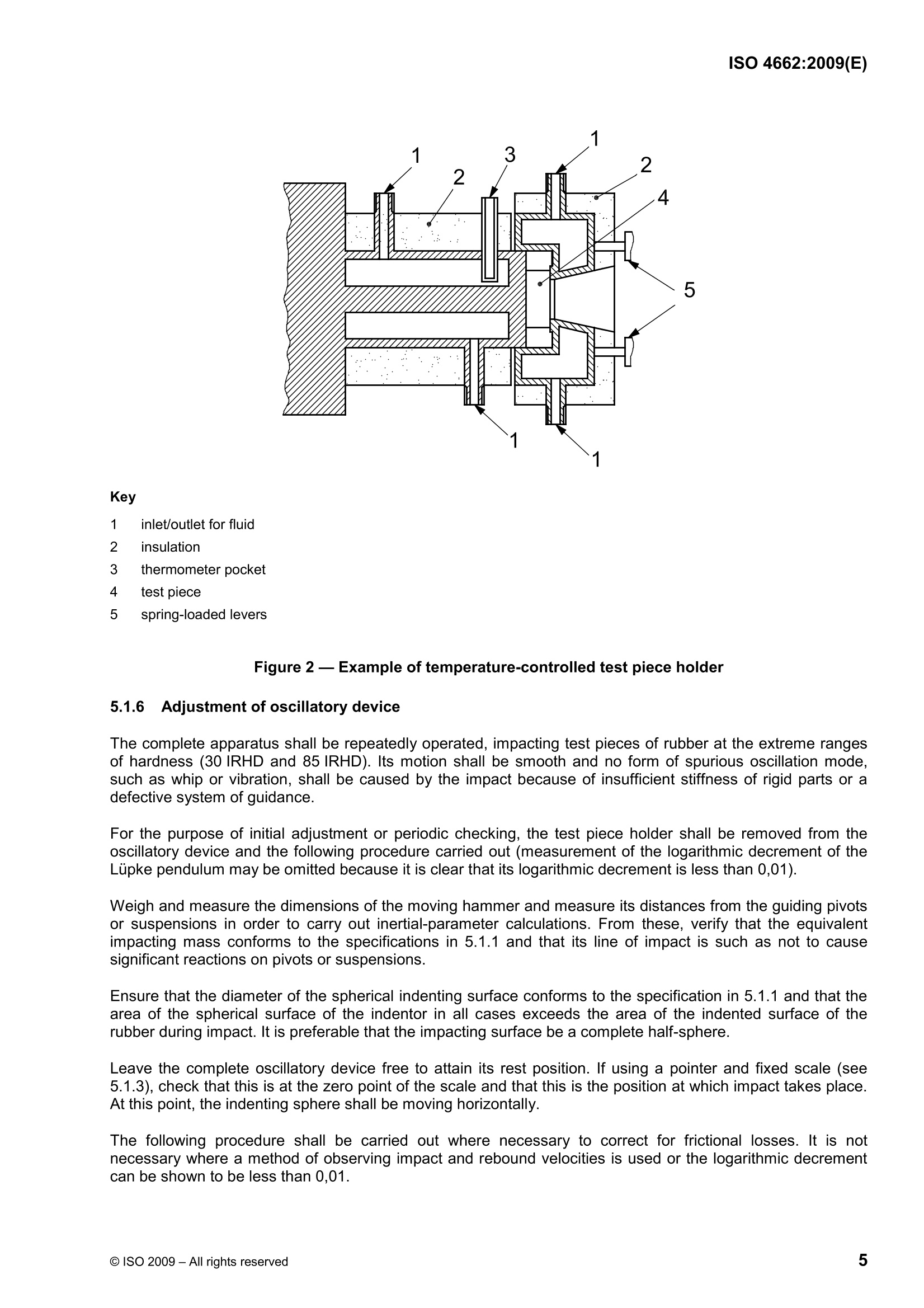
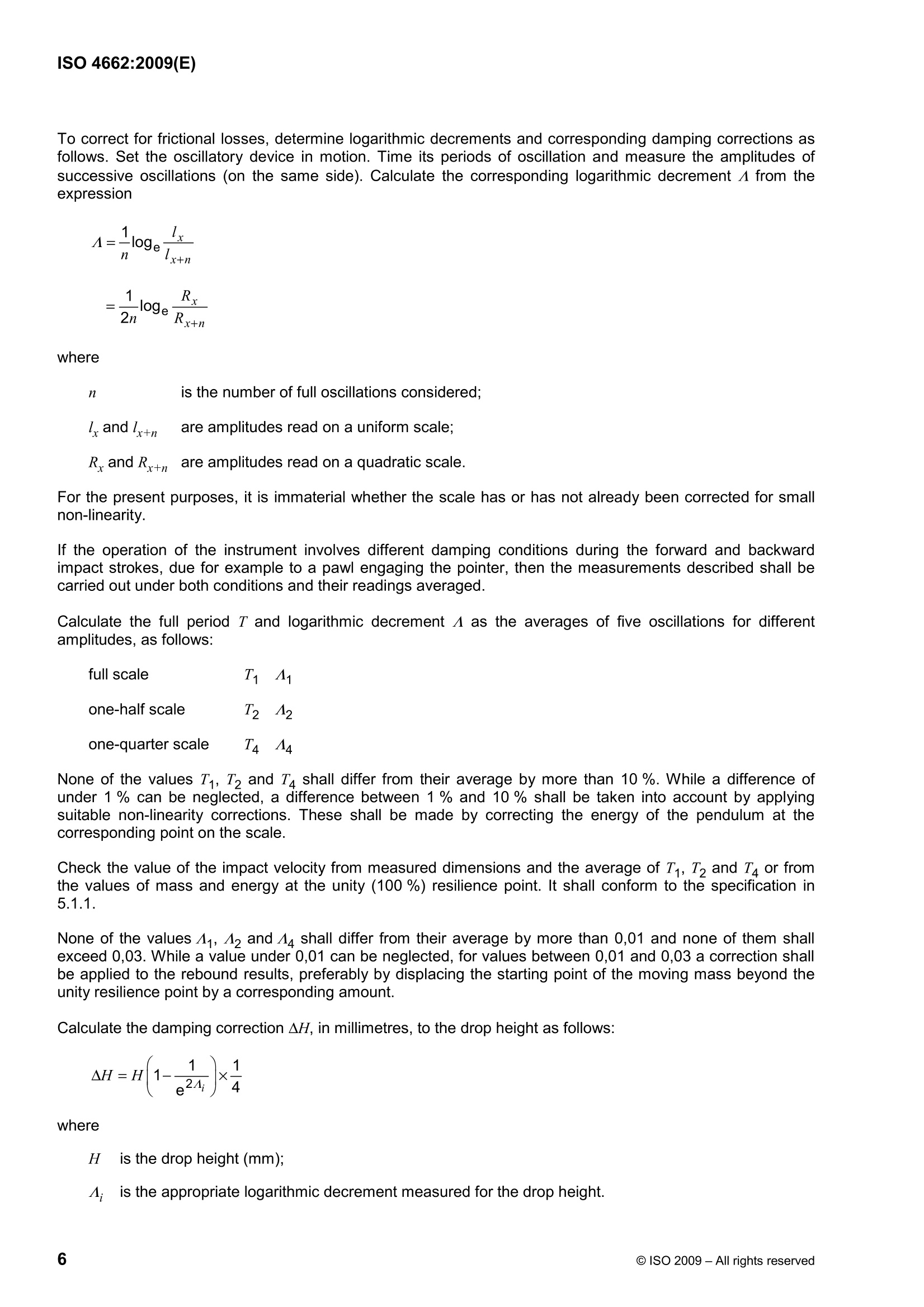
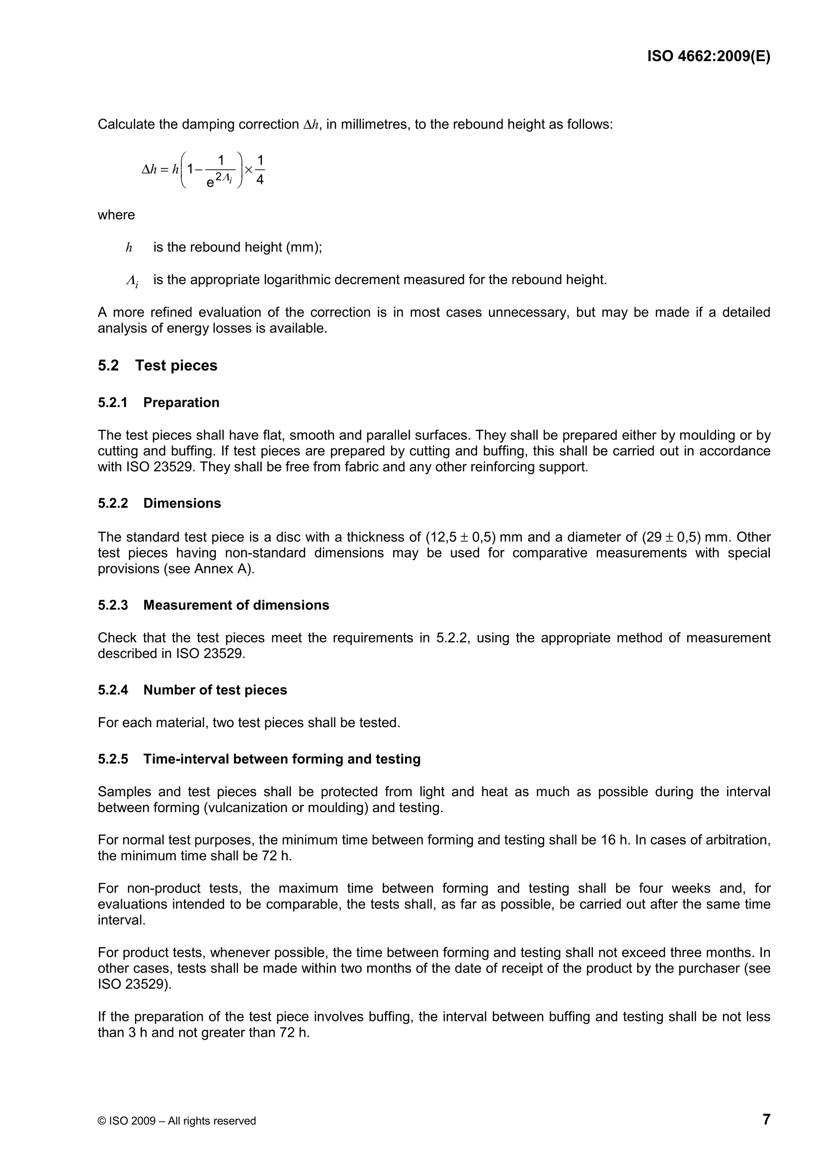
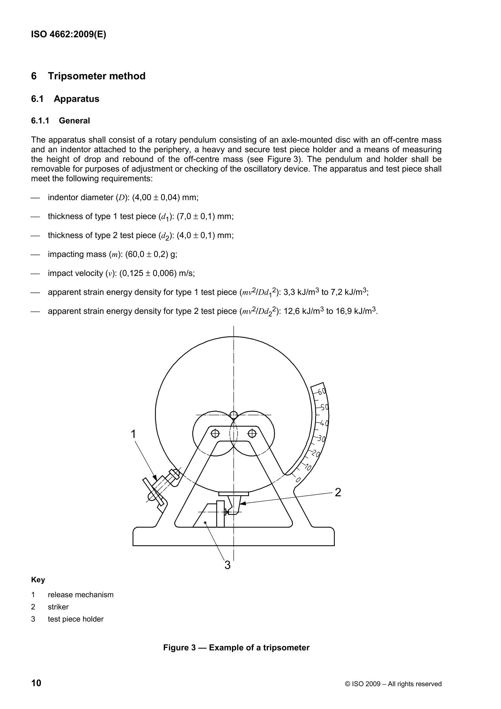
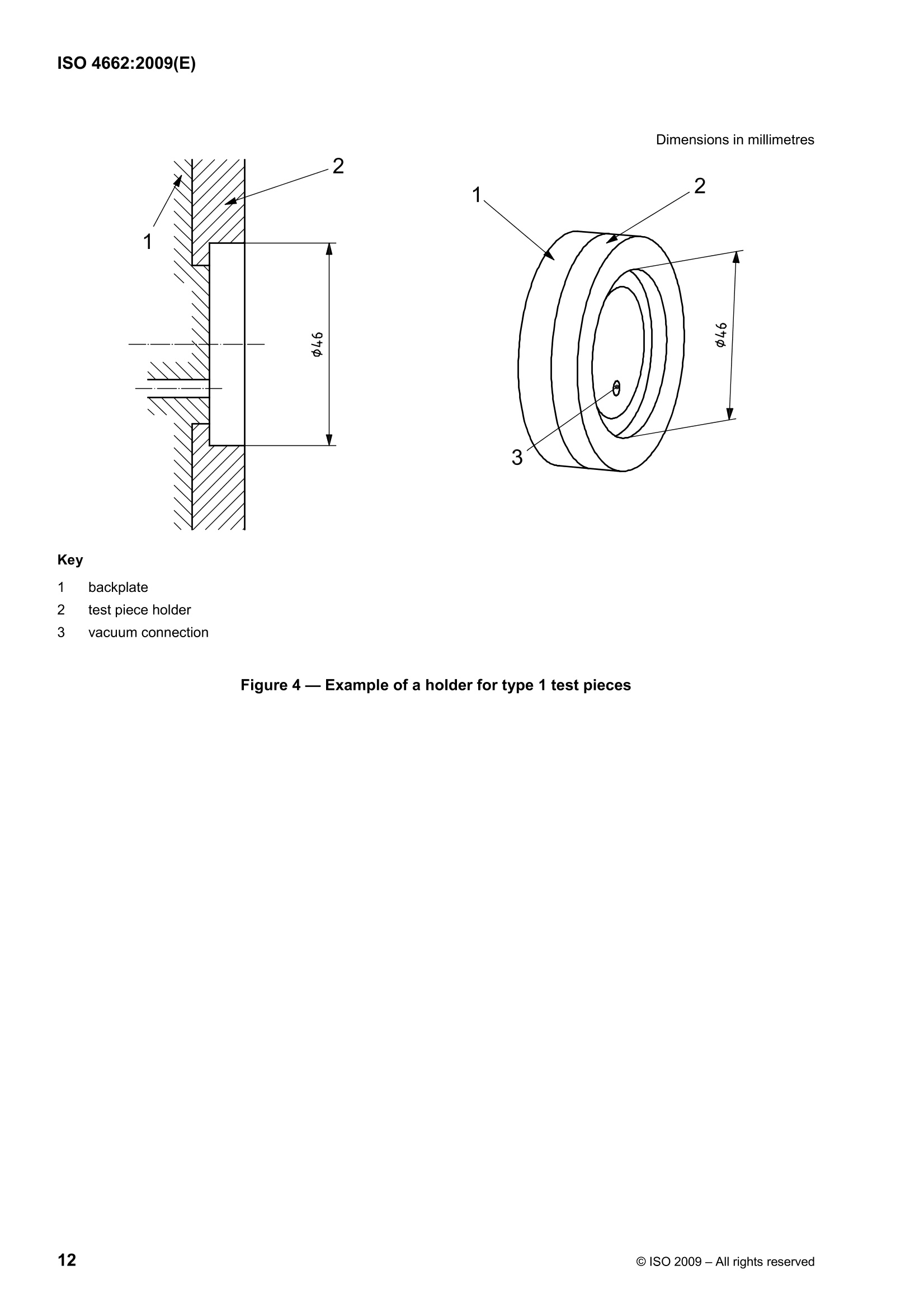
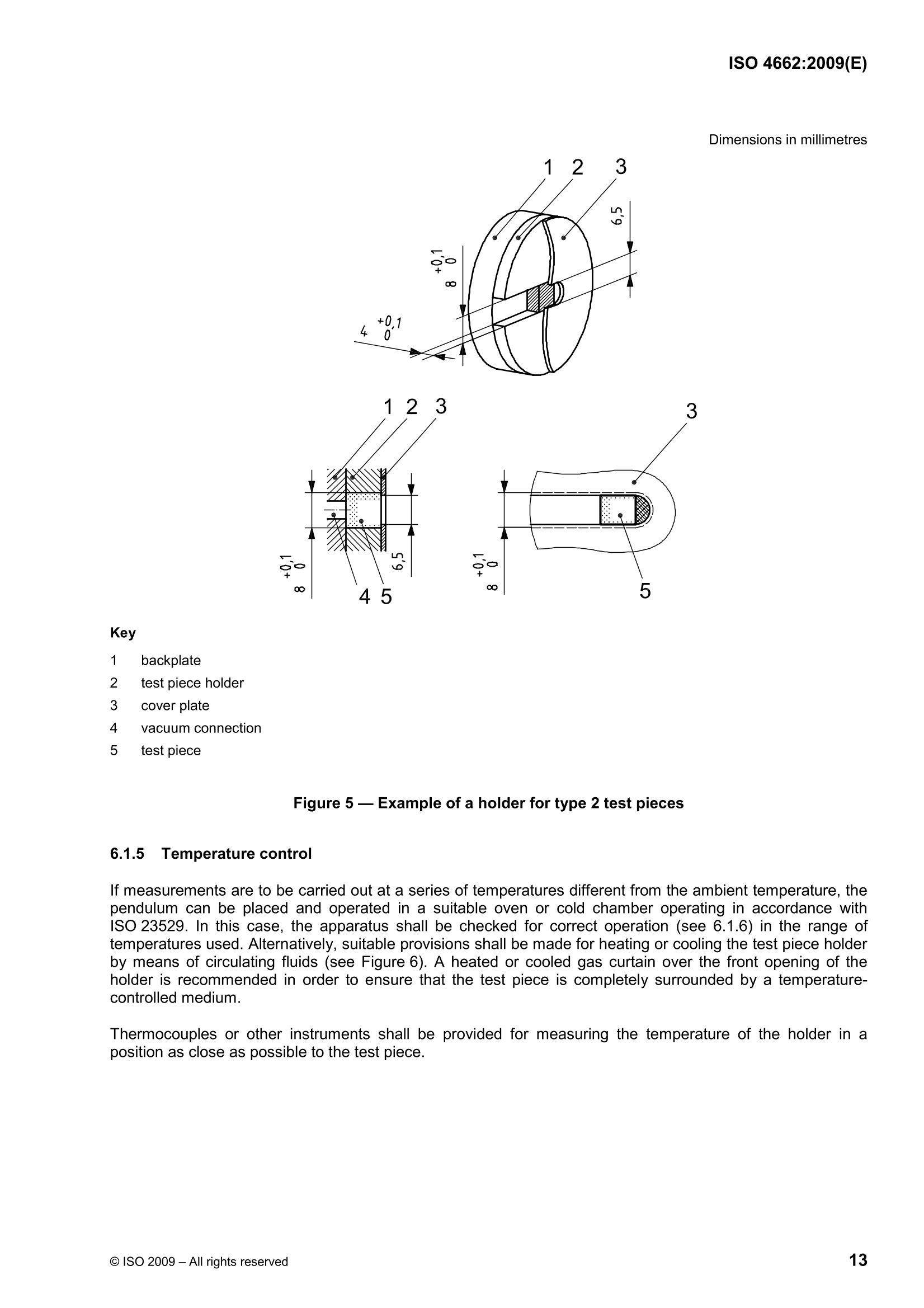
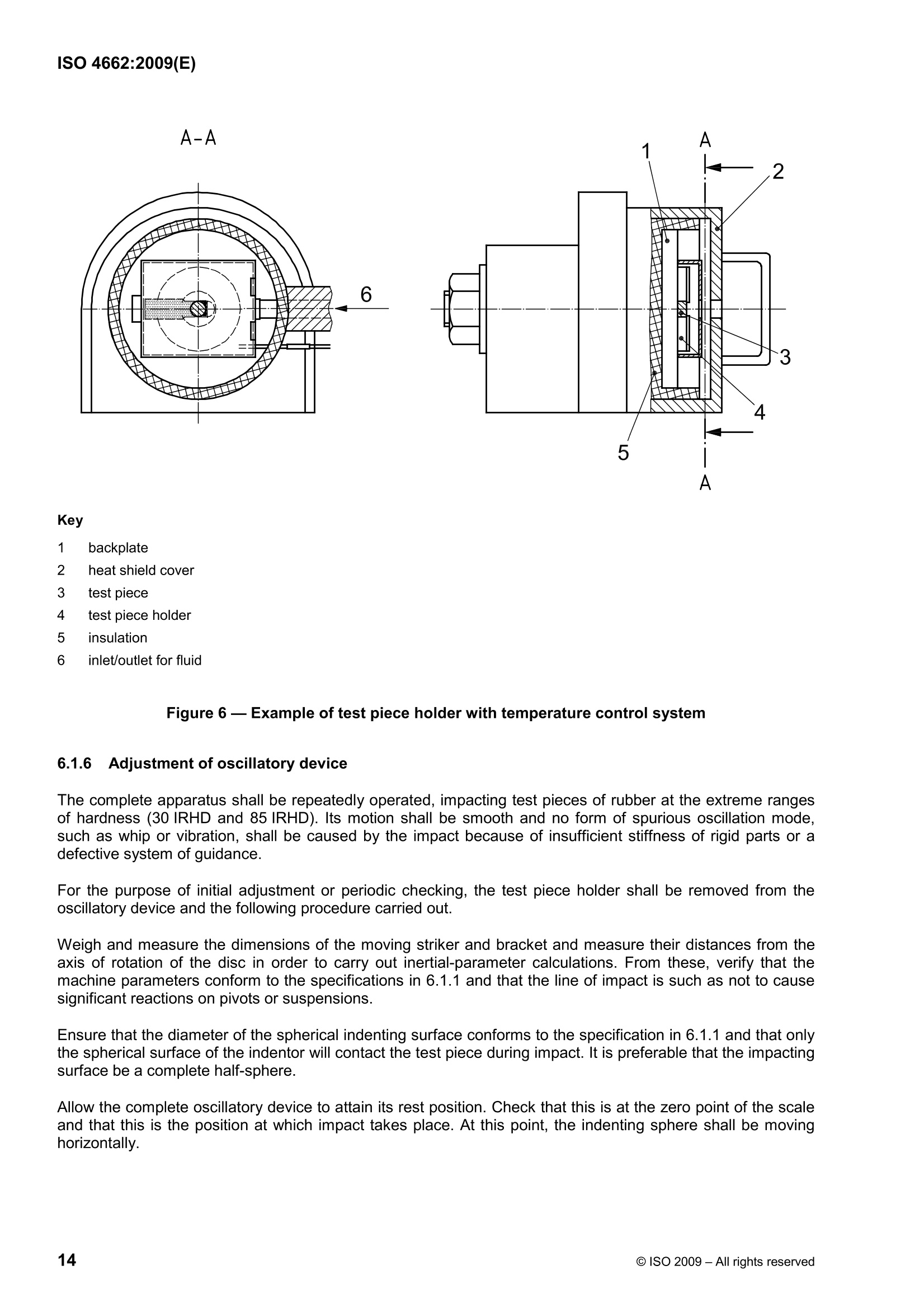
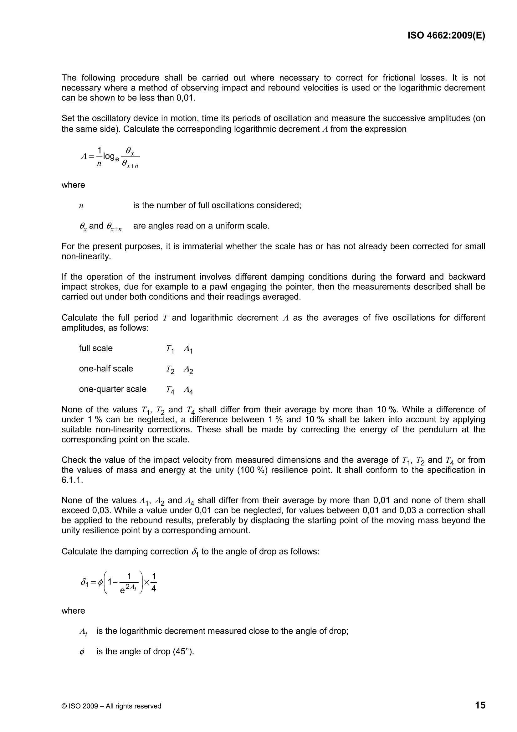
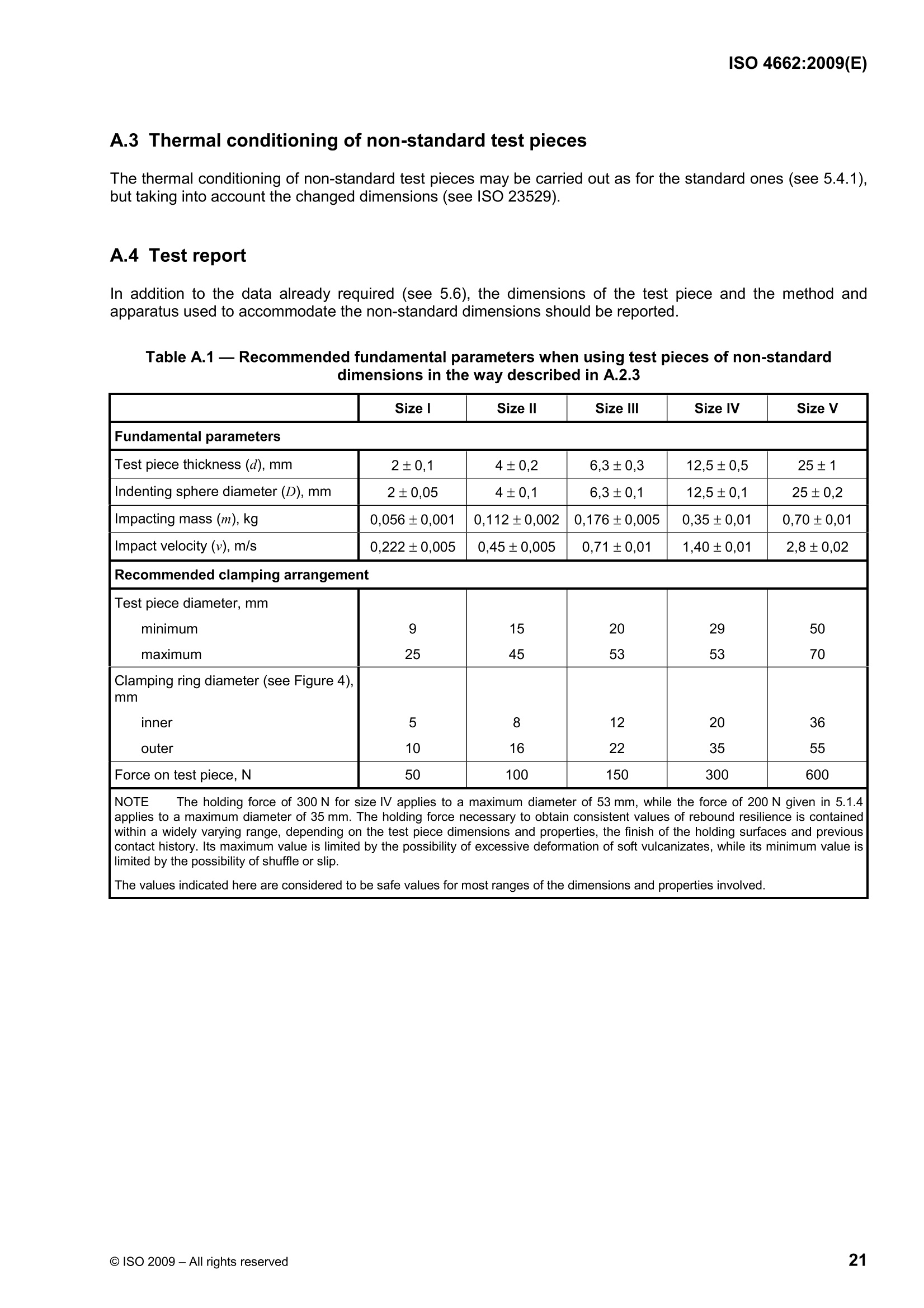
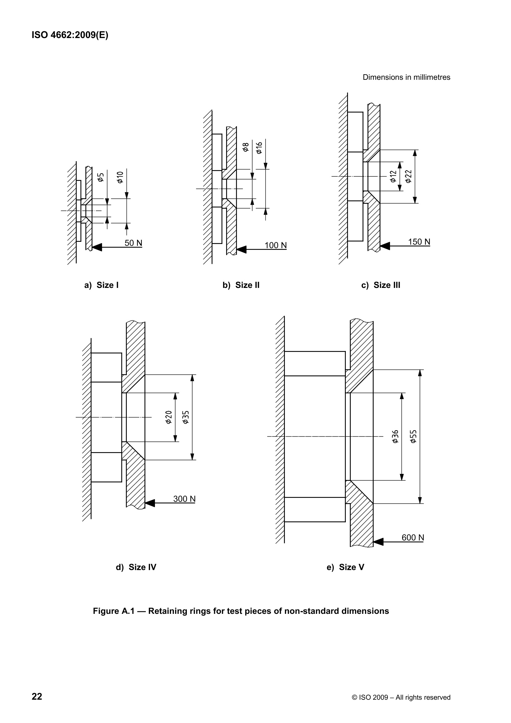
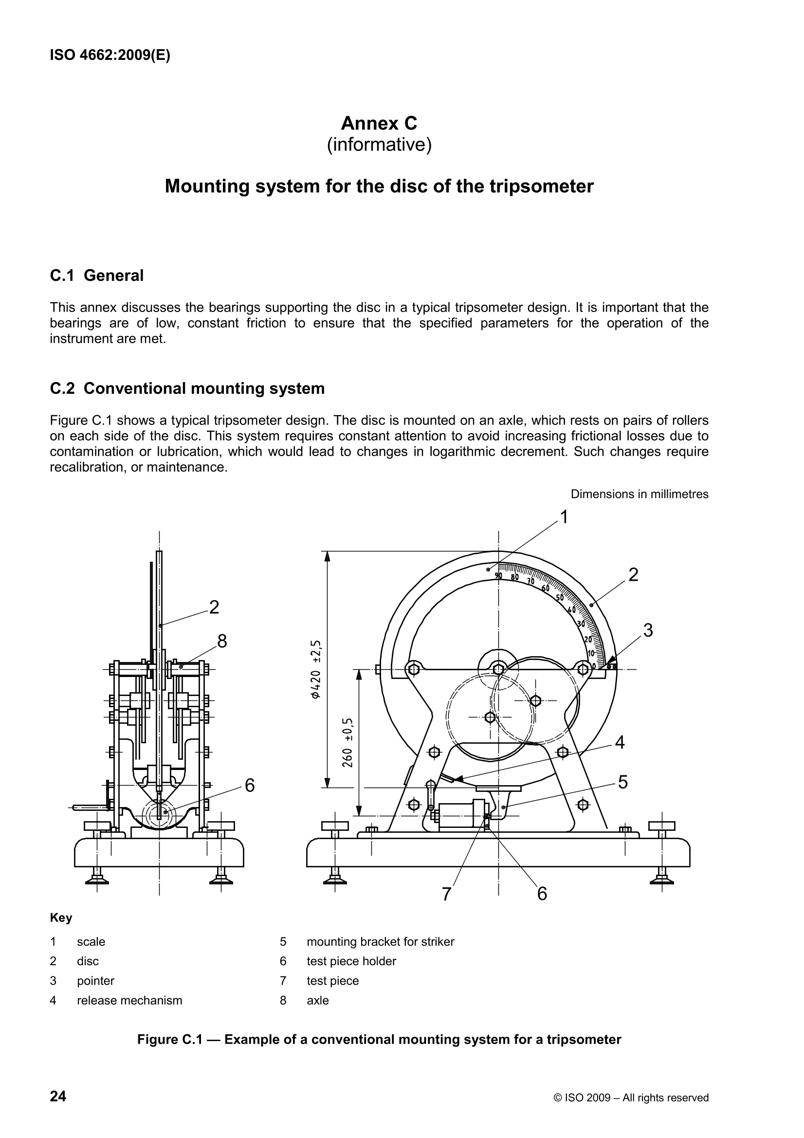
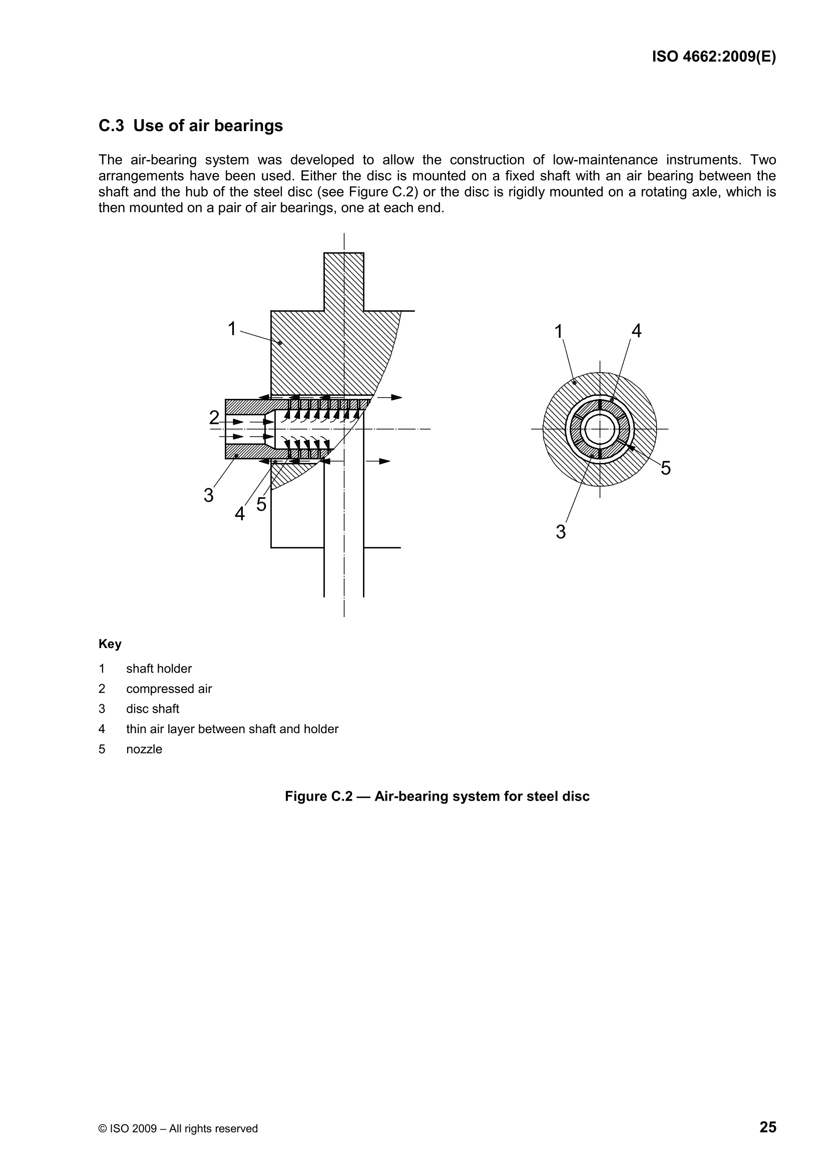
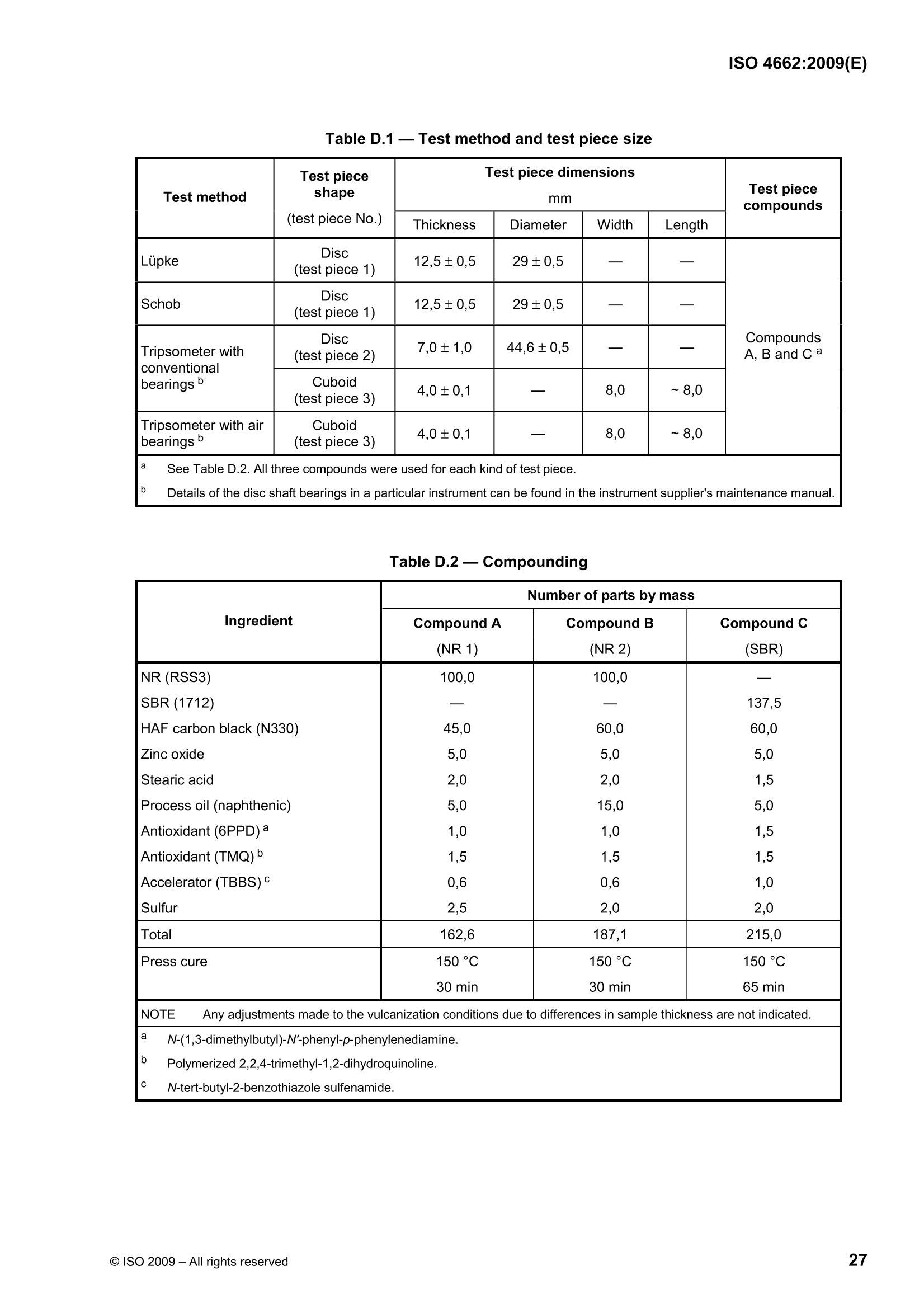
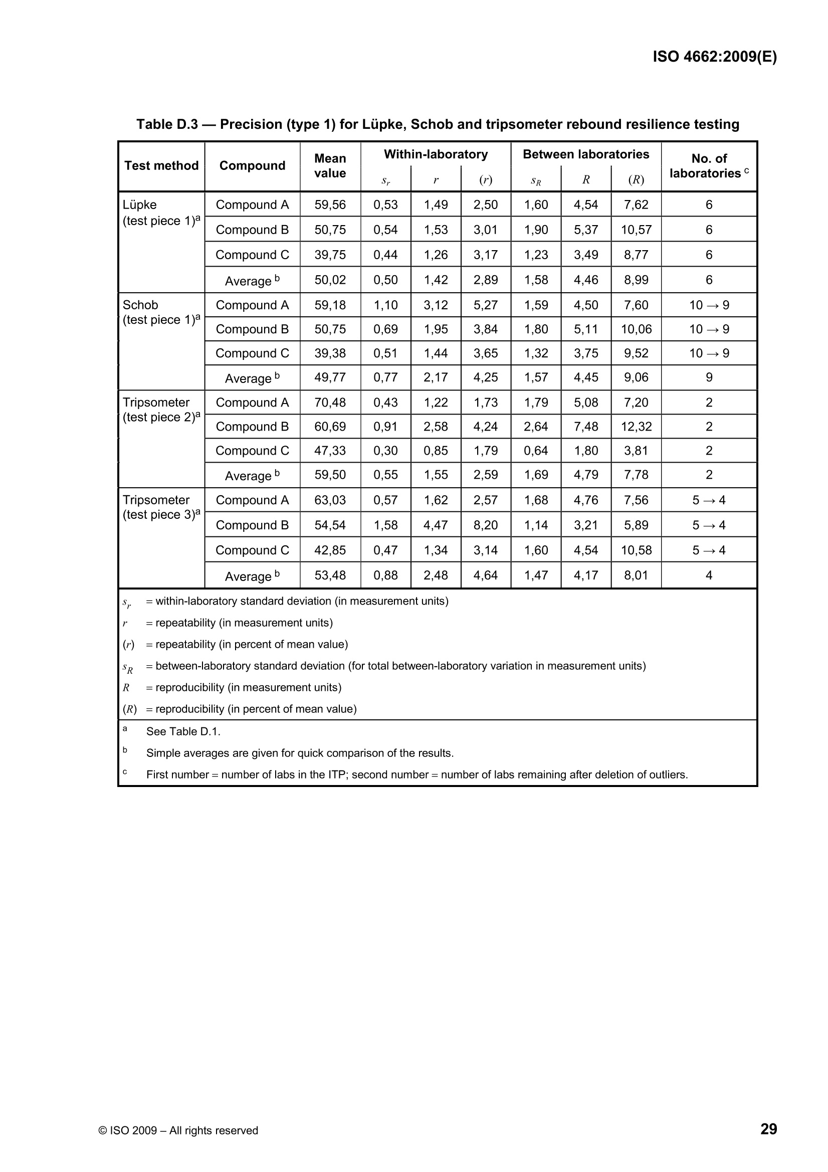
ISO 4662:2009(E) NTERNATIONAL STANDARD Third edition2009-08-15 Rubber, vulcanized or thermoplastic-Determination of rebound resilience Caoutchouc vulcanise ou thermoplastique-Determinationde la resilience de rebondissement Reference numberISO 4662:2009(E) PDF disclaimer COPYRIGHT PROTECTED DOCUMENT @ ISO 2009 All rights reserved. Unless otherwise specified, no part of this publication may be reproduced or utilized in any form or by any means,electronic or mechanical, including photocopying and microfilm, without permission in writing from either ISO at the address below orISO's member body in the country of the requester. ISO copyright office Case postale 56·CH-1211 Geneva 20 Tel. +41 22 749 01 11 Fax + 4122 749 09 47 E-mail copyright@iso.org Web www.iso.org Published in Switzerland Contents Page .Foreword..........iv Introduction.... ...V Scope.....1 2 Normative references........1 3Terms and definitions ..... .1 4Principle........2 5 Pendulum method . mmm Apparatus...... Test pieces.... .Temperature of test ... Procedure...... mmm mmmmmmm 227889 Precision...... 5.6 Test report......9 6 .Tripsometer method... 6.1Apparatus................................................................................................................................. 6.2 Test pieces .... 6.3 Temperature of test........17 6.4 Procedure...... Precision......86 on.......................................................................................................................................... Test report... 招招 Annex A (informative) Use of non-standard test pieces .... .20 Annex B (informative) Apparatus designs .........23 Annex C (informative) Mounting system for the disc of the tripsometer...... .24 Annex D (informative) Precision....... .26 Bibliography.............30 Foreword ISO (the International Organization for Standardization) is a worldwide federation of national standards bodies(ISO member bodies). The work of preparing International Standards is normally carried out through ISOtechnical committees. Each member body interested in a subject for which a technical committee has beenestablished has the right to be represented on that committee. International organizations, governmental andnon-governmental, in liaison with ISO, also take part in the work. ISO collaborates closely with theInternational Electrotechnical Commission (IEC) on all matters of electrotechnical standardization. International Standards are drafted in accordance with the rules given in the ISO/IEC Directives, Part 2. The main task of technical committees is to prepare International Standards. Draft International Standardsadopted by the technical committees are circulated to the member bodies for voting. Publication as anInternational Standard requires approval by at least 75 % of the member bodies casting a vote. Attention is drawn to the possibility that some of the elements of this document may be the subject of patentrights. ISO shall not be held responsible for identifying any or all such patent rights. ISO 4662 was prepared by Technical Committee ISO/TC 45, Rubber and rubber products, SubcommitteeSC 2, Testing and analysis. This third edition cancels and replaces the second edition (ISO 4662:1986), which has been technicallyrevised. The main change is the incorporation of a second method using a tripsometer. This method givesgenerally similar results, but uses a smaller test piece. Reference is also made to ISO 23529, which hasreplaced ISO 471, ISO 3383 and ISO 4661-1. Introduction When rubber is deformed, an energy input is involved; part of which is returned when the rubber returns to itsoriginal shape. That part of the energy which is not returned as mechanical energy is dissipated as heat in therubber. The ratio of the energy returned to the energy applied is termed the resilience. When the deformation is anindentation due to a single impact, this ratio is termed the rebound resilience. The value of the rebound resilience for a given material is not a fixed quantity, but varies with temperature,strain distribution (determined by the type of indentor and test piece and by their dimensions), strain rate(determined by the velocity of the indentor,), strain energy (determined by the mass and velocity of theindentor) and strain history. Strain history is particularly important in the case of filler-loaded polymers, wherethe stress-softening effect necessitates a mechanical conditioning. This variation of resilience with conditions is an inherent property of polymers, which can therefore only befully evaluated if tests are carried out over a wide range of conditions. The factors described may have adifferent quantitative influence on resilience. While temperature may critically affect resilience near transitionregions of the material tested, factors connected with time and amplitude of indentation have only moderateeffects,and fairly wide tolerances may be admissible for them. Ideally, rebound resilience should be measured on a test piece the back surface of which is bonded to a rigidsupport in order to avoid friction losses due to slippage during the impact. Since the use of bonded test piecesis impractical in many applications, unbonded test pieces are used. Frictional losses are avoided by secureclamping of the test piece. To approach these ideal conditions in a practical apparatus, it is necessary to put limitations upon thehardness (see ISO 48) of the rubber that may be tested: on the hard side to avoid unusual requirements ofrigidity in the apparatus; on the soft side to avoid difficulties in clamping. If a defined set of mechanical conditions and an appropriate apparatus are selected, a standard value ofrebound resilience at any temperature can be obtained with a satisfactory degree of reproducibility. Rubber, vulcanized or thermoplastic 一 Determinationof rebound resilience WARNING - Persons using this International Standard should be familiar with normal laboratorypractice. This standard does not purport to address all of the safety problems, if any, associated withits use. It is the responsibility of the user to establish appropriate safety and health practices and toensure compliance with any national regulatory conditions. CAUTION - Certain procedures specified in this International Standard may involve the use orgeneration of substances, or the generation of waste, that could constitute a local environmentalhazard. Reference should be made to appropriate documentation on safe handling and disposal afterUse. 1 Scope This International Standard specifies two methods for determining the rebound resilience of rubber thehardness of which lies between 30 IRHD and 85 IRHD. They are the pendulum method and the tripsometermethod. With the pendulum method, a mass with a spherical end impacts a flat test piece, firmly held but free to bulge.The kinetic energy of the impacting mass is measured immediately before and after impact. With the tripsometer method, a flat test piece is impacted by a hemisphere mounted on the periphery of a discwhich is supported on an axle and caused to rotate by an off-axis mass. The kinetic energy of the impactingmass is measured immediately before and afterimpact. 2 Normative references The following referenced documents are indispensable for the application of this document. For datedreferences only, the edition cited applies. For undated references, the latest edition of the referenceddocument (including any amendments) applies. ISO 48, Rubber, vulcanized or thermoplastic -Determination of hardness (hardness between 10 IRHD and100 IRHD) ISO 23529, Rubber - General procedures for preparing and conditioning test pieces for physical testmethods 3 Terms and definitions For the purposes of this document, the following terms and definitions apply. 3.1rebound resilience ratio between the returned and the applied energy of a moving mass which impacts a test piece NOTE It is usually expressed as a percentage. 4 Principle A test piece with plane, parallel surfaces is impacted on one surface by a linearly or circularly oscillating body,the impacting surface of which is spherical. The rebound resilience is determined by measurement of theenergy of the impacting mass immediately before and after impact. NOTE Conventionally, the input and output energies of the moving mass have been determined by observing thepotential energy of the mass when at rest before moving to impact the test piece and on reaching zero velocity afterrebound. The detailed descriptions of the apparatus described in this document follow this convention. However, it isequally acceptable to measure the input and output energies of the moving mass by observing its velocity immediatelybefore and after impact and calculating the kinetic energies. 5 Pendulum method 5.1 Apparatus 5.1.1 General The rebound resilience shall be measured by means of an apparatus consisting of a pendulum-like one-degree-of-freedom mechanical oscillatory device and a heavy and secure test piece holder. The two items shall be suitably fixed together for rebound resilience measurements, and either item can beremoved for purposes of adjustment or checking of the oscillatory device. Means shall be provided for measuring the rebound of the pendulum, either using a calibrated scale or anelectrical signal. Various practical designs of apparatus which conform to these specifications are available (see Annexes Band C). NOTE 1 The various types of apparatus designed to operate within the ranges specified for the various parameters(seebelow) and correctly calibrated give substantially the same values of rebound resilience. The apparatus and impacted test piece characteristics shall be such as to fall within the following specifiedranges: - indentor diameter (D): 12,45 mm to 15,05mm; test piece thickness (d): (12,5±0,5) mm; - iimrpacting mass (m): 0,34 kg to 0,35 kg; -impact velocity (v):1,4 m/s to 2,0 m/s;apparent strain energy density (mv2/Dd2): 324 kJ/m3 to 463 kJ/m3. NOTE 2 The conditions and apparatus specified in this International Standard involve the selection of a sphericalindentor and of a flat test piece and are assumed to be essentially dependent on the fundamental parameters D, d, m andv listed above. In addition, the ratio of impact energy to an equivalent volume, or "apparent strain energy density"(mv2/Dd), which under simplifying assumptions is related to impact strain, has to be maintained within the narrow rangespecified. NOTE 3 The ranges are such that they embrace the requirements for the Lupke pendulum method (12,5 mm, 12,5mmN.0,35kg, 1,4 m/s, 351 kJ/m3) and the modified Schob pendulum method (15,0 mm, 12,5 mm, 0,25 kg, 2m/s, 427 kJ/m3). In addition, allowance has been made for a) a small tolerance (±0,05 mm) to allow for mechanical imperfections of spheres of 12,5 mm and 15 mmnominal diameter: b) an additional tolerance (*12kJ/m3) on mv2/Dd2 to allow for the effect of variation in test piece thickness(±0,5 mm). 5.1.2 Oscillatory device The oscillatory device shall consist of a rigid body or hammer terminating in an indenting spherical surface,supported so as to oscillate linearly or circularly under the action of a restoring force which can be due togravity or produced by the elastic reaction of springs or by a wire in torsion. The velocity of the indentingspherical surface at the point of impact shall be in the horizontal direction and perpendicular to the surface ofthe test piece. 5.1.3 System for following the motion of the hammer The motion of the hammer shall be followed either by means of a system comprising a pointer and a fixedscale or by a system which measures the position or velocity of the hammer to furnish electrical signals. For pendulums in which the restoring force is due to gravity, the rebound resilience R is given by where h is the height of rebound; H is the drop height. It is usually convenient for the scale to measure either the horizontal rebound distance or, for rigid-armpendulums in particular, the angle of rebound.For pendulums in which the restoring force is due to a torsionwire or to the elastic reaction of springs, the rebound resilience is given by where . is the angle of rebound; 06 is the angle of impact. For this form of apparatus, it is convenient for the scale to be used to measure the angle of rebound. The scale can be graduated uniformly or be calibrated directly in units of resilience. For uniformly graduatedscales, conversion equations, charts or tables to allow the determination of the resilience are also necessary. 5.1.4 Test piece holder The disc-shaped test piece shall be securely held during mechanical conditioning and rebound measurement. The surface against which the back of the test piece is applied shall be metallic, flat and smoothly finished,vertical and perpendicular to the impact velocity direction. This backplate is part of an anvil which shall either be free, in which case it shall have a mass of at least200 times the impacting mass, or shall be rigidly fastened to a very rigid system, such as a masonry structure. Any type of suitable holding device can be used provided that it gives rebound resilience values that deviateby not more than 0,02 (absolute rebound resilience) from those obtained with test pieces bonded to a rigidbackplate. This shall be checked using one compound of high rebound resilience (approximately 0,90) andone of high hardness (approximately 85 IRHD). No lateral restraint shall be applied to the test piece. A clearance of at least 2 mm shall be left around it inorder to allow it to bulge freely when impacted. Examples of suitable holding devices include suction holding devices (by vacuum), mechanical clampingdevices and combinations of the two. In any of these cases, the holding device shall not cause excessdeformation of the surface to be impacted and shall not allow shuffling or slipping. A recommendedmechanical clamping device consists of a metal ring (see Figure 1) with a 20 mm internal diameter and 35 mmexternal diameter and able to exert on the front of the test piece a force of (200±20) N given, for example, bysprings. In this case, the indenting sphere shall enter, at its rest position, the centre of the retaining ring.Another recommended method of holding is by suction on the back of the test piece. This can be appliedthrough a circular groove, 25 mm in diameter and 2 mm in width, evacuated by a pump which maintains anabsolute pressure not greater than 10 kPa. In this case,the force exerted by the retaining ring can be reducedto (150±15)N. 5.1.5 Temperature control If measurements are to be carried out at a series of temperatures different from standard laboratorytemperature, the pendulum can be placed and operated in a suitable oven or cold chamber operating inaccordance with ISO 23529. In this case, the apparatus shall be checked for correct operation (see 5.1.6)over the range of temperatures used. Alternatively, suitable provisions shall be made for heating or cooling the test piece holder by means ofcirculating fluids (see Figure 2). A heated or cooled gas curtain over the front opening of the holder isrecommended in order to ensure that the test piece is completely surrounded by a temperature-controlledmedium. Thermocouples or other instruments shall be provided for measuring the temperature of the holder at aposition as close as possible to the test piece. Dimensions in millimetres Keyholding force: (150±15) N with suction or (200±20) N without suction Figure 1 - Mechanical clamping device (optional) Key 1 inlet/outlet for fluid 2 insulation 3 thermometer pocket 4 test piece 5 spring-loaded levers Figure 2 - Example of temperature-controlled test piece holder 5.1.6 Adjustment of oscillatory device The complete apparatus shall be repeatedly operated, impacting test pieces of rubber at the extreme rangesof hardness (30 IRHD and 85 IRHD). Its motion shall be smooth and no form of spurious oscillation mode,such as whip or vibration, shall be caused by the impact because of insufficient stiffness of rigid parts or adefective system of guidance. For the purpose of initial adjustment or periodic checking, the test piece holder shall be removed from theoscillatory device and the following procedure carried out (measurement of the logarithmic decrement of theLupke pendulum may be omitted because it is clear that its logarithmic decrement is less than 0,01). Weigh and measure the dimensions of the moving hammer and measure its distances from the guiding pivotsor suspensions in order to carry out inertial-parameter calculations. From these, verify that the equivalentimpacting mass conforms to the specifications in 5.1.1 and that its line of impact is such as not to causesignificant reactions on pivots or suspensions. Ensure that the diameter of the spherical indenting surface conforms to the specification in 5.1.1 and that thearea of the spherical surface of the indentor in all cases exceeds the area of the indented surface of therubber during impact. It is preferable that the impacting surface be a complete half-sphere. Leave the complete oscillatory device free to attain its rest position. If using a pointer and fixed scale (see5.1.3), check that this is at the zero point of the scale and that this is the position at which impact takes place.At this point, the indenting sphere shall be moving horizontally. The following procedure shall be carried out where necessary to correct for frictional losses. It is notnecessary where a method of observing impact and rebound velocities is used or the logarithmic decrementcan be shown to be less than 0,01. To correct for frictional losses, determine logarithmic decrements and corresponding damping corrections asfollows. Set the oscillatory device in motion. Time its periods of oscillation and measure the amplitudes ofsuccessive oscillations (on the same side). Calculate the corresponding logarithmic decrement A from theexpression where 7 is the number of full oscillations considered: l.and lx+n are amplitudes read on a uniform scale; R. and Ry++nn aare amplitudes read on a quadratic scale. For the present purposes, it is immaterial whether the scale has or has not already been corrected for smallnon-linearity. If the operation of the instrument involves different damping conditions during the forward and backwardimpact strokes, due for example to a pawl engaging the pointer, then the measurements described shall becarried out under both conditions and their readings averaged. Calculate the full period T and logarithmic decrement A as the averages of five oscillations for differentamplitudes, as follows: full scale T one-quarter scale T4 44 None of the values T, T2 and T4 shall differ from their average by more than 10 %. While a difference ofunder 1 % can be neglected, a difference between 1% and 10 % shall be taken into account by applyingsuitable non-linearity corrections. These shall be made by correcting the energy of the pendulum at thecorresponding point on the scale. Check the value of the impact velocity from measured dimensions and the average of T1, T2 and T4 or fromthe values of mass and energy at the unity (100 %) resilience point. It shall conform to the specification in5.1.1. None of the values 4, 42 and A4 shall differ from their average by more than 0,01 and none of them shallexceed 0,03. While a value under 0,01 can be neglected, for values between 0,01 and 0,03 a correction shallbe applied to the rebound results, preferably by displacing the starting point of the moving mass beyond theunity resilience point by a corresponding amount. Calculate the damping correction AH, in millimetres, to the drop height as follows: where H is the drop height (mm); 4 is the appropriate logarithmic decrement measured for the drop height. Calculate the damping correction Ah, in millimetres, to the rebound height as follows: where h is the rebound height (mm); 4. is the appropriate logarithmic decrement measured for the rebound height. A more refined evaluation of the correction is in most cases unnecessary, but may be made if a detailedanalysis of energy losses is available. 5.21Test pieces 5.2.1 Preparation The test pieces shall have flat, smooth and parallel surfaces. They shall be prepared either by moulding or bycutting and buffing. If test pieces are prepared by cutting and buffing, this shall be carried out in accordancewith ISO 23529. They shall be free from fabric and any other reinforcing support. 5.2.2 Dimensions The standard test piece is a disc with a thickness of (12,5±0,5) mm and a diameter of (29±0,5) mm. Othertest pieces having non-standard dimensions may be used for comparative measurements with specialprovisions (see Annex A). 5.2.3 Measurement of dimensions Check that the test pieces meet the requirements in 5.2.2, using the appropriate method of measurementdescribed in ISO 23529. 5.2.4 Number of test pieces For each material, two test pieces shall be tested. 5.2.5 Time-interval between forming and testing Samples and test pieces shall be protected from light and heat as much as possible during the intervalbetween forming (vulcanization or moulding) and testing. For normal test purposes, the minimum time between forming and testing shall be 16 h. In cases of arbitration,the minimum time shall be 72 h. For non-product tests, the maximum time between forming and testing shall be four weeks and, forevaluations intended to be comparable, the tests shall, as far as possible, be carried out after the same timeinterval. For product tests, whenever possible, the time between forming and testing shall not exceed three months. Inother cases, tests shall be made within two months of the date of receipt of the product by the purchaser (seeISO 23529). If the preparation of the test piece involves buffing, the interval between buffing and testing shall be not lessthan 3 h and not greater than 72 h. 5.2.6 Conditioning Prepared test pieces shall be conditioned immediately before testing for a minimum period of 3 h at one of thestandard laboratory temperatures specified in ISO 23529. The same temperature shall be used throughoutany one test or series of tests intended to be comparable. 5.3 Temperature of test The temperature or temperature range of the test shall be chosen according to the material being tested andthe information required. Preference shall be given to the temperatures listed in ISO 23529. The tolerancelimits on the temperature shall be not more than ±1°℃. When no temperature is specified, a standardlaboratory temperature shall be chosen. Where the resilience changes quickly with temperature, the use of more temperatures at closer intervals isrecommended. 5.4 Procedure 5.4.1 Thermal conditioning and mounting of test piece lf stickiness is noted on the impacted surface, its effect shall be avoided by dusting the surface lightly, forexample with talc. If the test temperature differs from the standard laboratory temperature chosen (see 5.3), first bring thecomplete test apparatus, or the special heated or cooled holder (see 5.1.5), to the test temperature. Mount the test piece in the holder and allow sufficient time for the test piece to reach a uniform temperaturewithin the prescribed tolerance limits (see ISO 23529). Alternatively, test pieces may be heated or cooledseparately from the holder in an oven or cold chamber in accordance with ISO 23529 and then quicklyinserted in the heated or cooled holder. In this case, the time in the holder before testing shall preferably bereduced to 3 min. In tests at low temperatures, provision shall be made to prevent frost from forming on the test piece. 5.4.2 Mechanical conditioning of test piece After applying the prescribed thermal conditioning and mounting the test piece in the holder, carry out amechanical conditioning by subjecting the test piece to not fewer than three and not more than sevensuccessive impacts, so as to reach a practically constant rebound amplitude. 5.4.3 Measurement of rebound resilience Immediately after the impacts for mechanical conditioning, carry out three more impacts on the test piece andnote the three rebound readings. 5.4.4 Calculation and expression of results Where no corrections are necessary, calculate the rebound resilience using the appropriate equation in 5.1.3. Where correction of drop height and rebound height is necessary, the rebound resilience is calculated usingthe following equation: where RL is the rebound resilience (%); is the rebound height (mm); H is the drop height (mm); Ah is the damping correction to the rebound height (mm); H is the damping correction to the drop height (mm). Take the median of the resilience values calculated for each of the three impacts on the test piece as therebound resilience of the test piece. Calculate the mean of the median values for the two test pieces. 5.5 Precision Precision data for this method is given in Annex D. 5.6 Test report The test report shall include the following particulars: a)sample details: 1) a full description of the sample and its origin, the method of preparation of the test pieces from the sample, for example moulded or cut; b)test method: 1) a full reference to the test method used, i.e. the number of this International Standard and“pendulummethod", 2) the type of apparatus used and the indentor diameter, mass and velocity, 3) if the standard test piece was not used, details of the test piece, the method used to hold the test piece; c) test details: 1) the time and temperature of conditioning of the test pieces prior to testing, 2) the temperature of the test, and the relative humidity if necessary, details of any procedures not specified in this International Standard; d) test results: 1) the number of test pieces tested, 2) the individual test results, 3) the mean result: e) the date of the test. 6Tripsometer method 6.1 Apparatus 6.1.1 General The apparatus shall consist of a rotary pendulum consisting of an axle-mounted disc with an off-centre massand an indentor attached to the periphery, a heavy and secure test piece holder and a means of measuringthe height of drop and rebound of the off-centre mass (see Figure3). The pendulum and holder shall beremovable for purposes of adjustment or checking of the oscillatory device. The apparatus and test piece shallmeet the following requirements: -indentor diameter (D): (4,00±0,04) mm;thickness of type 1 test piece (d):(7,0±0,1) mm; thickness of type 2 test piece (d): (4,0±0,1) mm; -iirmpacting mass (m): (60,0±0,2)g; - impact velocity (v): (0,125±0,006) m/s; —apparent strain energy density for type 1 test piece (mv2/Dd 2): 3,3 kJ/m3 to 7,2 kJ/m3; apparent strain energy density for type 2 test piece (mv2/Dd2): 12,6 kJ/m3 to 16,9 kJ/m3. Key 1 release mechanism 2 striker 3 test piece holder Figure 3-Example of a tripsometer 6.1.2 Pendulum The pendulum shall consist of a solid steel disc (420±2,5)mm in diameter and with a mass of(16,5±0,05)kg. The disc shall carry on its periphery a bracket holding a steel ball or hemispherical striker(4±0,04) mm in diameter, with its centre (260±0,5) mm from the centre of the disc. The ball and brackettogether shall add an unbalanced mass of (60±0,2) g. The unbalanced mass shall be in such a position thatthe time for one complete oscillation (amplitude about 45°) of the disc plus unbalanced mass is (10±0,5)s. The disc shall be mounted on bearings designed to impart a minimum of friction to the system. It shall beprovided with a mechanism permitting it to be held, displaced 45°from the impact position, until released. Therelease mechanism shall not impart any impulse to the disc (see Figure 3). NOTE 1 Details of the determination of the logarithmic decrement of the oscillating device and the maximumpermissible value are given in 6.1.6. NOTE 2 A design using air bearings to minimize friction is described in Annex C. 6.1.3 System for following the motion of the disc The motion of the disc shall be followed either by means of a system comprising a pointer or vernier rigidlyfixed to the disc, travelling along a scale carried on the frame of the machine, thus measuring the angulardisplacement of the disc, or by a system which determines the angular velocity of the disc immediately beforeand immediately after impact. If a scale is used, it shall be graduated either in degrees of arc or directly inpercentage rebound resilience. The spacing of the graduation marks shall be such that the percentagerebound resilience can be determined to an accuracy of±1. For pendulums in which the restoring force is due to gravity, the rebound resilience R is given by where is the rebound angle; is the angle of drop (45°). 6.1.4 Test piece holder The test piece holder shall hold the test piece firmly against a rigid anvil. The test piece shall be so held that,when the pendulum is in its position of equilibrium, the striker just touches the centre of the test surface of thetest piece. The test piece shall be held by one of the following (or by a combination of them): a) A metal clamping ring acting on the front surface of the test piece. A recommended device consists of ametal ring (see Figure 4) 46 mm in internal diameter and exerting, on the front of the test piece, a force of(2±0,1) N produced, for example, by springs. b) Suction acting through holes in the anvil near the periphery of the test piece. A recommended method ofholding is by applying suction to the back of the test piece by a pump which maintains an absolutepressure not greater than 10 kPa (see Figure 5). Key 1 backplate 2 test piece holder 3 vacuum connection Figure 4 -Example of a holder for type 1 test pieces Dimensions in millimetres Key backplate 2 test piece holder 3 cover plate 4 vacuum connection 5 test piece Figure 5- Example of a holder for type 2 test pieces 6.1.5 Temperature control lf measurements are to be carried out at a series of temperatures different from the ambient temperature, thependulum can be placed and operated in a suitable oven or cold chamber operating in accordance withISO 23529. In this case, the apparatus shall be checked for correct operation (see 6.1.6) in the range oftemperatures used. Alternatively, suitable provisions shall be made for heating or cooling the test piece holderby means of circulating fluids (see Figure6). A heated or cooled gas curtain over the front opening of theholder is recommended in order to ensure that the test piece is completely surrounded by a temperature-controlled medium. Thermocouples or other instruments shall be provided for measuring the temperature of the holder in aposition as close as possible to the test piece. A Key 1 backplate 2 heat shield cover 3 test piece 4 test piece holder 5 insulation 6 inlet/outlet for fluid Figure 6-Example of test piece holder with temperature control system 6.1.6 Adjustment of oscillatory device The complete apparatus shall be repeatedly operated, impacting test pieces of rubber at the extreme rangesof hardness (30 IRHD and 85 IRHD). Its motion shall be smooth and no form of spurious oscillation mode,such as whip or vibration, shall be caused by the impact because of insufficient stiffness of rigid parts or adefective system of guidance. For the purpose of initial adjustment or periodic checking, the test piece holder shall be removed from theoscillatory device and the following procedure carried out. Weigh and measure the dimensions of the moving striker and bracket and measure their distances from theaxis of rotation of the disc in order to carry out inertial-parameter calculations. From these, verify that themachine parameters conform to the specifications in 6.1.1 and that the line of impact is such as not to causesignificant reactions on pivots or suspensions. Ensure that the diameter of the spherical indenting surface conforms to the specification in 6.1.1 and that onlythe spherical surface of the indentor will contact the test piece during impact. It is preferable that the impactingsurface be a complete half-sphere. Allow the complete oscillatory device to attain its rest position. Check that this is at the zero point of the scaleand that this is the position at which impact takes place. At this point, the indenting sphere shall be movinghorizontally. The following procedure shall be carried out where necessary to correct for frictional losses. It is notnecessary where a method of observing impact and rebound velocities is used or the logarithmic decrementcan be shown to be less than 0,01. Set the oscillatory device in motion, time its periods of oscillation and measure the successive amplitudes (onthe same side). Calculate the corresponding logarithmic decrement A from the expression where is the number of full oscillations considered: e.and ex+n are angles read on a uniform scale. For the present purposes, it is immaterial whether the scale has or has not already been corrected for smallnon-linearity. If the operation of the instrument involves different damping conditions during the forward and backwardimpact strokes, due for example to a pawl engaging the pointer, then the measurements described shall becarried out under both conditions and their readings averaged. Calculate the full period T and logarithmic decrement A as the averages of five oscillations for differentamplitudes, as follows: full scale T 4 one-quarter scale T4 44 None of the values T, T2 and T4 shall differ from their average by more than 10 %. While a difference ofunder 1% can be neglected, a difference between 1% and 10% shall be taken into account by applyingsuitable non-linearity corrections. These shall be made by correcting the energy of the pendulum at thecorresponding point on the scale. Check the value of the impact velocity from measured dimensions and the average of T, T2 and T4 or fromthe values of mass and energy at the unity (100%) resilience point. It shall conform to the specification in6.1.1. None of the values 4, 42and A4 shall differ from their average by more than 0,01 and none of them shallexceed 0,03. While a value under 0,01 can be neglected, for values between 0,01 and 0,03 a correction shallbe applied to the rebound results, preferably by displacing the starting point of the moving mass beyond theunity resilience point by a corresponding amount. Calculate the damping correction 8 to the angle of drop as follows: where is the logarithmic decrement measured close to the angle of drop; 0 is the angle of drop (45°). Calculate the damping correction 8to the rebound angle as follows: where is the rebound angle; 4; is the logarithmic decrement measured close to the rebound angle. A more refined evaluation of the correction is in most cases unnecessary, but may be made if a detailedanalysis of energy losses in available. 6.2 Test pieces 6.2.1 Preparation The test pieces shall have flat, smooth and parallel surfaces.They shall be prepared either by moulding or bycutting and buffing. If test pieces are prepared by cutting and buffing, this shall be carried out in accordancewith ISO 23529. They shall be free from fabric and any other reinforcing support 6.2.2 Dimensions The test piece shall be l either a disc with a diameter of (44,6±0,5)mm and a thickness of (7 ± 1,0) mm (type 1); . or a cuboid measuring (8±0,5) mm by (8±0,5) mm by (4±0,1) mm (type 2). The latter test piece is particularly suitable when a number of tests are being conducted at a series oftemperatures, as thermal equilibrium is achieved in a shorter time per test than when the larger and thickerdisc-shaped test pieces are used. 6.2.3 Measurement of dimensions Check that the test pieces meet the requirements in 6.2.2, using the appropriate method of measurementdescribed in ISO 23529. 6.2.4 Number of test pieces For each material, two test pieces shall tested. 6.2.5 Time-interval between forming and testing Samples and test pieces shall be protected from light and heat as much as possible during the intervabetween forming (vulcanization or moulding) and testing. For normal test purposes, the minimum time between forming and testing shall be 16 h. In cases of arbitration,the minimum time shall be 72 h. For non-product tests, the maximum time between forming and testing shall be four weeks and, forevaluations intended to be comparable, the tests shall, as far as possible,be carried out after the same timeinterval. For product tests, whenever possible, the time between forming and testing shall not exceed three months. Inother cases, tests shall be made within two months of the date of receipt of the product by the purchaser (seeISO 23529). If the preparation of the test piece involves buffing, the interval between buffing and testing shall be not lessthan 3 h and not greater than 72 h. 6.2.6 Conditioning Prepared test pieces shall be conditioned immediately before testing for a minimum period of 3 h at one of thestandard laboratory temperatures specified in ISO 23529. The same temperature shall be used throughoutany one test or series of tests intended to be comparable. 6.3 .Temperature of test The preferred temperature of test is one of the standard laboratory temperatures specified in ISO 23529.When other temperatures are required, these shall be selected from the list of preferred temperatures given inlSO 23529. The tolerance limits on the temperature shall be not more than ±1 °C. Where the resilience changes quickly with temperature, the use of more temperatures at closer intervals isrecommended. 6.4 Procedure 6.4.1 Thermal conditioning and mounting of test piece If stickiness is shown on the impacted surface, its effect shall be avoided by lightly dusting the front surfaceonly, for example with talc Ensure that the test piece and test piece holder are thoroughly clean. Wipe the rear surface of the test piecewith solvent to reduce shuffle (slight movement of the test piece during impact). Bring the test piece holder tothe test temperature, insert the test piece and leave it in position for a sufficient time for it to reach the testtemperature (see ISO 23529). A period of at least 15 min is required for 7-mm-thick test pieces. This periodcan, however, be shortened by first bringing the test piece to the test temperature in a chamber separate fromthe test piece holder. In tests at low temperatures, provision shall be made to prevent frost from forming on the test piece. Errors can arise if the test piece temperature is assumed to be that of the test piece holder. It is thereforerecommended that the temperature of the test piece be measured by means of a fine-wire thermocoupleinserted into the rubber in such a way that it does not interfere with the pendulum. 6.4.2 Mechanical conditioning of test piece After applying the prescribed thermal conditioning, carry out a mechanical conditioning by subjecting the testpiece to not fewer than three and not more than seven successive impacts of the pendulum from its releaseposition of 45°, so as to reach practically constant rebound amplitude. 6.4.3 Measurement Immediately after the impacts for mechanical conditioning, apply three more impacts to the test piece and notethe three rebound readings. NOTE When using the thin type 2 test piece, it has been found useful to release the pendulum at 25°to thehorizontal to reduce the energy of impact, particularly when softer rubbers are being tested. If this is done, the results willnot necessarily equate with those obtained using a type 1 test piece. 6.4.4 Calculation and expression of results Where a calibrated scale of rebound resilience is not provided,calculate the percentage rebound resilience R-for each test using either or where a is the velocity after impact; is the velocity before impact; is the rebound angle; o is the angle of drop (45°); 8. is the damping correction for angle o; is the damping correction for angle 0. Express the final percentage rebound resilience as the mean of the two individual results. 6.5 Precision Precision data for this method are given in Annex D. 6.6 Test report The test report shall include the following particulars: a) sample details: 1) a full description of the sample and its origin, 2) compound details and cure details, where appropriate, 3) the method of preparation of the test pieces from the sample, for example moulded or cut; b) test method: 1) a full reference to the test method used, i.e. the number of this International Standard and"tripsometer method", 2) the type of apparatus used and the indentor diameter, mass and velocity, 3) the type of test piece used, 4) the method used to hold the test piece; c) test details: 1) the laboratory temperature, 2) the time and temperature of conditioning of the test pieces prior to testing, the temperature of the test, and the relative humidity if necessary, 4) details of any procedures not specified in this International Standard; d) test results: 1) the number of test pieces tested, 2) the individual test results. 3) the mean result: e) the date of the test. Annex A(informative) Use of non-standard test pieces A.1 Non-standard diameter Test pieces of standard thickness but having a diameter larger than standard, up to a maximum of 53 mm,may be tested. They will give results close to those obtained with the standard procedure and apparatus,provided an increased holding force is used (see Table A.1). A.2 Non-standard thickness A.2.1 General The rebound resilience may be measured with test pieces having a thickness differing from, and in generallower than, (12,5±0,5) mm. Such test pieces will give nrFesults close to those obtained with the standardprocedure, provided either the adjustments described in A.2.2 or those described in A.2.3 are made. Both arebased on the principle of maintaining the apparent strain energy density mv2/Ddat a constant value of351 kJ/m3. Test pieces may also be stacked (see A.2.4). A.2.2 Adjustment of the impact velocity The impact velocity v is reduced proportionally to the test piece thickness. This reduction in velocity can easilybe obtained by changing the starting point and initial deviation of the hammer whilst keeping the indentordiameter and impacting mass at their standard values (see 5.1.1). In order to be able to hold thinner test pieces with the standard clamping ring, the clamping action of the lattershould be supplemented by the use of suction (see 5.1.4). While these adjustments give results which may show some discrepancies from standard rebound resilience,because of different strain distribution and poorer test piece holding, it has the advantage of simplicitybecause a single type of apparatus, with minor adjustments, may accommodate different thicknesses. A.2.3 Adjustment of the indentor diameter, indentor mass and impact velocity The indentor diameter D, the indentor mass m and the impact velocity v are all changed proportionally to thetest piece thickness (see Table A.1). It is also necessary to change the test piece diameter, the holding ringdiameter and the holding force to suit the new thickness (see Table A. 1 and Figure A.1). These adjustments obviously require different sizes of apparatus to be used and, unless only a single non-standard thickness is to be tested, are therefore more expensive. They have the important advantage,however, of giving results very close to the standard rebound resilience. A.2.4 Stacked test pieces A stack, of no more than three thin test pieces of the same material, may be used to obtain a greater testpiece thickness. It is necessary that the surfaces of the test pieces be very smooth, and lateral suction mayhelp in ensuring their close contact. Stacking of test pieces can introduce additional errors and should therefore be used only for comparativemeasurements. A.3 Thermal conditioning of non-standard test pieces The thermal conditioning of non-standard test pieces may be carried out as for the standard ones (see 5.4.1),but taking into account the changed dimensions (see ISO 23529). A.4 Test report In addition to the data already required (see 5.6), the dimensions of the test piece and the method andapparatus used to accommodate the non-standard dimensions should be reported. Table A.1一Recommended fundamental parameters when using test pieces of non-standarddimensions in the way described in A.2.3 Size I Size ll Sizelll Size IV Size V Fundamental parameters Test piece thickness (d), mm 2±0,1 4±0,2 6,3±0,3 12,5±0,5 25±1 Indenting sphere diameter (D), mm 2±0,05 4±0,1 6,3±0,1 12,5±0,1 25±0,2 Impacting mass (m), kg 0,056±0,001 0,112±0,002 0,176±0,005 0,35±0,01 0,70±0,01 Impact velocity (v), m/s 0,222±0,005 0,45±0,005 0,71±0,01 1,40±0,01 2,8±0,02 Recommended clamping arrangement Test piece diameter, mmminimum maximum 925 1545 2053 2953 5070 Clamping ring diameter (see Figure 4),mm inner outer 510 8 16 12 22 2035 36 55 Force on test piece, N 50 100 150 300 600 NOTE The holding force of 300 N for size lV applies to a maximum diameter of 53 mm, while the force of 200 N given in 5.1.4applies to a maximum diameter of 35 mm. The holding force necessary to obtain consistent values of rebound resilience is containedwithin a widely varying range, depending on the test piece dimensions and properties, the finish of the holding surfaces and previouscontact history.Its maximum value is limited by the possibility of excessive deformation of soft vulcanizates, while its minimum value islimited by the possibility of shuffle or slip. The values indicated here are considered to be safe values for most ranges of the dimensions and properties involved. 150 N a) Sizel b) Size ll c) Size Ill Figure A.1 一 Retaining rings for test pieces of non-standard dimensions Annex B (informative) Apparatus designs B.1 General References are given here to designs of apparatus which, suitably dimensioned and constructed, will conformto this International Standard. B.2 Lupke pendulum The moving hammer of the Lupke pendulum is essentially a cylindrical bar ending in a spherical surface andsupported by a quadrifilar suspension. This system oscillates under the action of gravity. The hammer has a mass of 0,35 kg and the spherical surface has a diameter of 12,5 mm. The length of thewire suspension is 2 m and the initial angle is such that the mass is raised by 0,1 m. Details of the apparatus are given in Reference [1] (see the Bibliography). B.3 Schob pendulum This is a rigid pendulum consisting of a hammer, terminating in a spherical indenting surface 15 mm indiameter, and a rod about 200 mm in length connecting the hammer to a pivot. The dimensions and masses should be such that, when the pendulum is lifted through a right angle from itsrest position and released, the hammer impacts the test piece with a velocity of 2 m/s and an energy of 0,5 J. The original Schob pendulum, described in Reference [2], involves the use of a 6-mm-thick test piece and istherefore outside the range of specifications given in this International Standard. However, a modified version,which uses a 12,5-mm-thick test piece, comes within the range of specifications in this International Standard. B.4 Zerbini pendulum This pendulum consists of a bar having a spherical indentor fixed transversely to one end and rotating underthe action of a taut torsion wire which is suitably connected, at its centre-point, to the bar and at its ends tofixed points. This design, which can be constructed with a wide range of fundamental parameters, is described inReference [3]. (informative) Mounting system for the disc of the tripsometer C.1 General This annex discusses the bearings supporting the disc in a typical tripsometer design.It is important that thebearings are of low, constant friction to ensure that the specified parameters for the operation of theinstrument are met. C.2 Conventional mounting system Figure C.1 shows a typical tripsometer design. The disc is mounted on an axle, which rests on pairs of rollerson each side of the disc. This system requires constant attention to avoid increasing frictional losses due tocontamination or lubrication, which would lead to changes in logarithmic decrement. Such changes requirerecalibration, ormaintenance. Key 1 scale 5 mounting bracket for striker 2 disc 6 test piece holder 3 pointer 7 test piece 4 release mechanism 8 axle Figure C.1 一 Example of a conventional mounting system for a tripsometer C.3 Use of air bearings The air-bearing system was developed to allow the construction of low-maintenance instruments. Twoarrangements have been used. Either the disc is mounted on a fixed shaft with an air bearing between theshaft and the hub of the steel disc (see Figure C.2) or the disc is rigidly mounted on a rotating axle, which isthen mounted on a pair of air bearings, one at each end. Key 1 shaft holder 2 compressed air 3 disc shaft 4 thin air layer between shaft and holder 5 nozzle Figure C.2 -Air-bearing system for steel disc Annex D (informative) Precision D.1 Background An interlaboratory test programme (ITP) to determine the precision of the methods specified in thisInternational Standard was conducted in 2007, using the procedures and guidelines described inISO/TR 9272:2005 [4]. Refer to ISO/TR 9272:2005 for details of, and terminology on, precision determination. Since the test methods involve rather detailed and complex operations to conduct a measurement effectivelya number of these details are outlined in Clause D.2. Refer to this for important information on the ITP. A“testresult is the mean of the rebound resilience values measured (for the specified number of impacts) for twotest pieces. The precision analysis was based on test result data, i.e. two test result values per laboratory permaterial or compound for each of two test days one week apart. The numbers of participating laboratories aregiven in Table D.3. The precision results as determined from this ITP may not be applied to acceptance or rejection testing forany group of materials or products without documentation that the results of this precision determinationactually apply to the materials or products tested. D.2 Details of the ITP D.2.1 Precision type A type 1 precision was determined. D.2.2 Test method Testing was carried out with Lupke and Schob pendulums and with tripsometers having conventional and airbearings. D.2.3 Test pieces The dimensions of the test pieces used are given Table D.1. For the details of the compounding of thematerials, see Table D.2. Table D.1 一 Test method and test piece size Test method Test pieceshape (test piece No.) Test piece dimensions mm Test piececompounds Thickness Diameter Width Length Lupke Disc(test piece 1) 12,5±0,5 29±0,5 二 Compounds A, B and C a Schob Disc (test piece 1) 12,5±0,5 29±0,5 — Tripsometer withconventional bearings ° Disc (test piece 2) 7,0±1,0 44,6±0,5 — Cuboid(test piece 3) 4,0±0,1 8,0 ~8,0 Tripsometer with airbearings Cuboid(test piece 3) 4,0±0,1 8,0 ~8,0 a See Table D.2. All three compounds were used for each kind of test piece. b Details of the disc shaft bearings in a particular instrument can be found in the instrument supplier's maintenance manual. Table D.2 .-Compounding Press cure 150 °C 150°C 30 min 150°C 30 min Compound B(NR 2) 65 min Compound C(SBR) NOTE Any adjustments made to the vulcanization conditions due to differences in sample thickness are not indicated. 100,0 a N-(1,3-dimethylbutyl)-N'-phenyl-p-phenylenediamine. b Polymerized 2,2,4-trimethyl-1,2-dihydroquinoline. c N-tert-butyl-2-benzothiazole sulfenamide. 60,0 60,0 5,0 60,0 5,0 2,0 1,5 1,0 1,5 0,6 2,0 5,0 1,5 1,5 D.3 Precision results D.3.1 General The precision results for all the test instruments and for the test pieces selected for each test instrument aregiven in Table D.3 for all three compounds. General statements concerning the use of the precision resultsare made below. These are given in terms of both the absolute precision,r and R (in measurement units), andrelative precision, (r) and (R) (as a percentage). D.3.2 Repeatability The repeatability, or local domain precision, for each of the rebound resilience methods has been establishedfor each material as the values given in Table D.3. D.3.3 Reproducibility The reproducibility, or global domain precision, for each of the rebound resilience methods has beenestablished for each material as the values given in Table D.3. D.3.4 Comments on the precision The precision with the Lupke and Schob pendulums appears to be very similar. The mean rebound resilienceis the same, the repeatability with the Schob pendulum is slightly higher than with the Lupke, but thereproducibility is the same with both. The tripsometer gives, for both test pieces, rebound resilience valueswhich are higher than those obtained with the Lupke and Schob pendulums, but there appears to be nosubstantial difference in either repeatability or reproducibility. Tripsometer test piece 2 (disc) gives higherrebound resilience values than test piece 3 (cuboid). D.3.5 Bias Bias is the difference between a measured average test result and a reference or true value for themeasurement in question. Reference values do not exist for this test method, and therefore bias cannot bedetermined. Table D.3 - Precision (type 1) for Lupke,Schob and tripsometer rebound resilience testing Test method Compound Meanvalue No. oflaboratories Sr T (r) SR R (R) Lupke(test piece 1)a Compound A 59,56 0,53 1,49 2,50 1,60 4,54 7,62 6 Compound B 50,75 0,54 1,53 3,01 1,90 5,37 10,57 6 Compound C 39,75 0,44 1,26 3,17 1,23 3,49 8,77 6 Average 50,02 0,50 1,42 2,89 1,58 4,46 8,99 6 Schob (test piece 1) Compound A 59,18 1,10 3,12 5,27 1,59 4,50 7,60 10→9 Compound B 50,75 0,69 1,95 3,84 1,80 5,11 10,06 10→9 Compound C 39,38 0,51 1,44 3,65 1,32 3,75 9,52 10→9 Average 49,77 0,77 2,17 4,25 1,57 4,45 9,06 9 Tripsometer (test piece 2)a Compound A 70,48 0,43 1,22 1,73 1,79 5,08 7,20 2 Compound B 60,69 0,91 2,58 4,24 2,64 7,48 12,32 2 Compound C 47,33 0,30 0,85 1,79 0,64 1,80 3,81 2 Average 59,50 0,55 1,55 2,59 1,69 4,79 7,78 2 Tripsometer (test piece 3)a Compound A 63,03 0,57 1,62 2,57 1,68 4,76 7,56 5→4 Compound B 54,54 1,58 4,47 8,20 1,14 3,21 5,89 5→4 Compound C 42,85 0,47 1,34 3,14 1,60 4,54 10,58 5→4 Average 53,48 0,88 2,48 4,64 1,47 4,17 8,01 4 =within-laboratory standard deviation (in measurement units) r =repeatability (in measurement units) (r)= repeatability (in percent of mean value) R=between-laboratory standard deviation (for total between-laboratory variation in measurement units) R = reproducibility (in measurement units) (R)= reproducibility (in percent of mean value) a See Table D.1. b Simple averages are given for quick comparison of the results. c First number= number of labs in the ITP; second number= number of labs remaining after deletion of outliers. Bibliography ( [1] LUPKE, I r.P. The impact resiliometer, Rubber Chemistry and Technology, Vol. 7 ( 1934), p. 5 91 ) ( [2] ScHOB, A. Mitteilungen aus dem staatlichen Materialprufungsamt, Berlin, 19 1 9, p. 227 ) [3] ZERBINI, V. Torsion resilience pendulum, Rubber Chemistry and Technology, Vol.43(1970),pp. 1005-1014 41 ISO/TR 9272:2005, Rubber and rubber products - Determination of precision for test methodstandards ISO 4662:2009(E) ( ICS 83.060 ) ( Price based on 30 pages ) @ ISO ij ISO -All rights reserved
确定


还剩35页未读,是否继续阅读?

标准集团(香港)有限公司为您提供《橡胶中回弹性检测方案 》,该方案主要用于橡胶及其制品中回弹性检测,参考标准--,《橡胶中回弹性检测方案 》用到的仪器有
相关方案
更多