


方案详情
文
光学镊子最早是被Ashkin在1970年报道的,Ashkin第一个描述了小粒子是如何被高度聚焦的激光束捕捉到,并能够在3-D空间进行可控式移动。但是,现代的光学镊子通常安装起来非常复杂,而且需要专家来操作。最近几年商业化的光学镊子开始成功上市,但是很难操作,需要定期的维护和校准,离快捷使用还很遥远。
欧洲一家年轻的高科技公司Aresis在发展Tweez系列光学镊子的领域中已经拥有超过10年的经验。Tweez250si拥有非常紧凑的设计使得其具有超凡的稳定性和准确性,它含有一个非常稳定的由声光偏转器(AOD)定向和控制的激光器,通过该技术可以产生大约200个以上的光学势阱,同时捕获200个目标分子或者粒子,并且势阱的转换速度可以达到100KHz,以确保每个被捕获的离子处于近乎固定的状态。安装使用方便快捷,使得该技术成功地被欧洲多所大学和研究所引进使用。近几年相关技术发表多篇文章,包括Science和Nature等顶级期刊。
方案详情

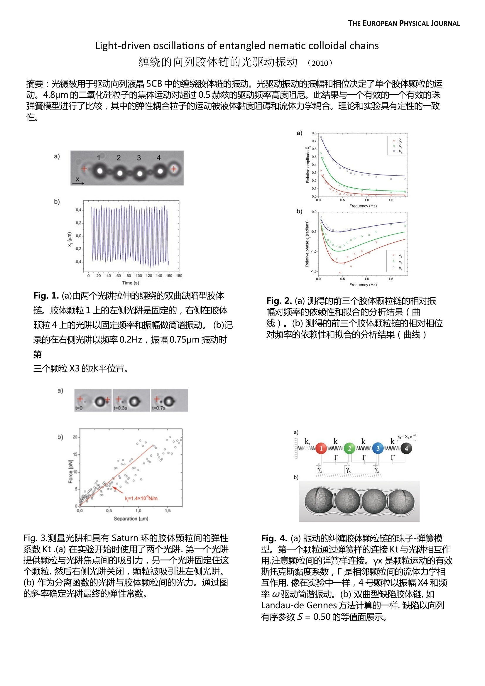
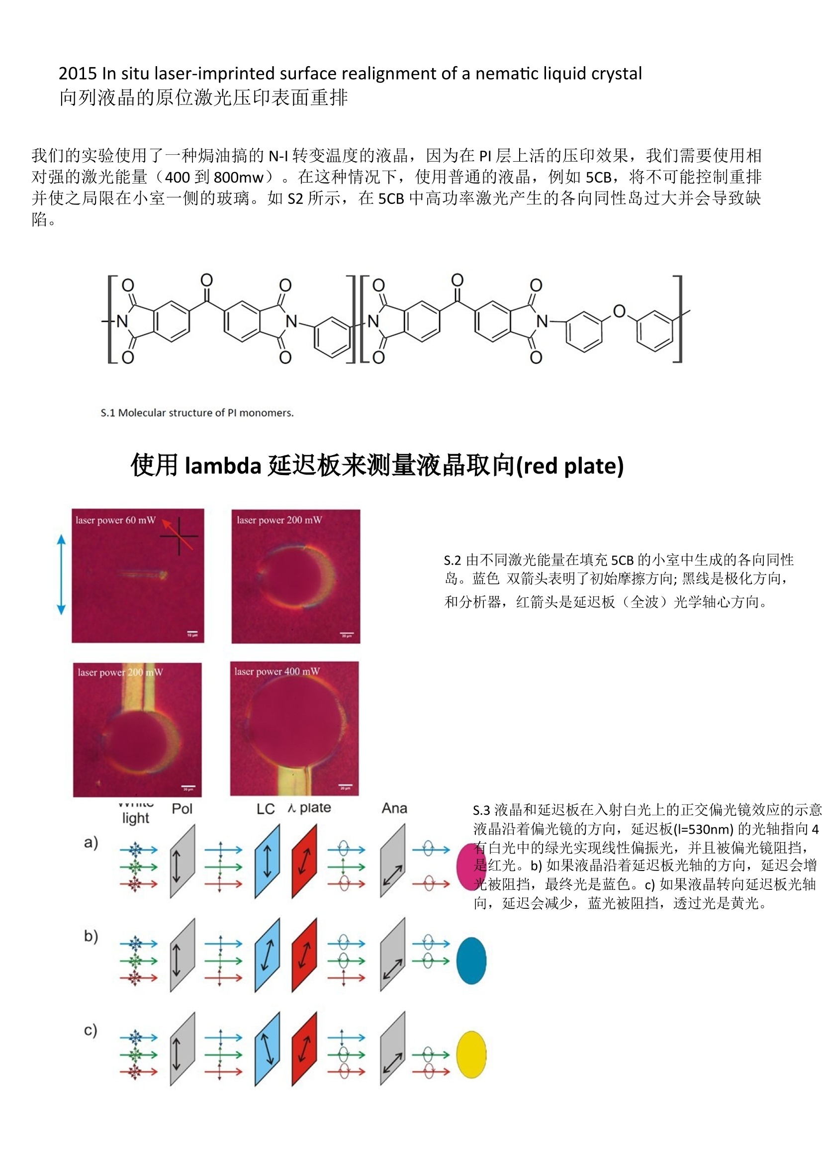
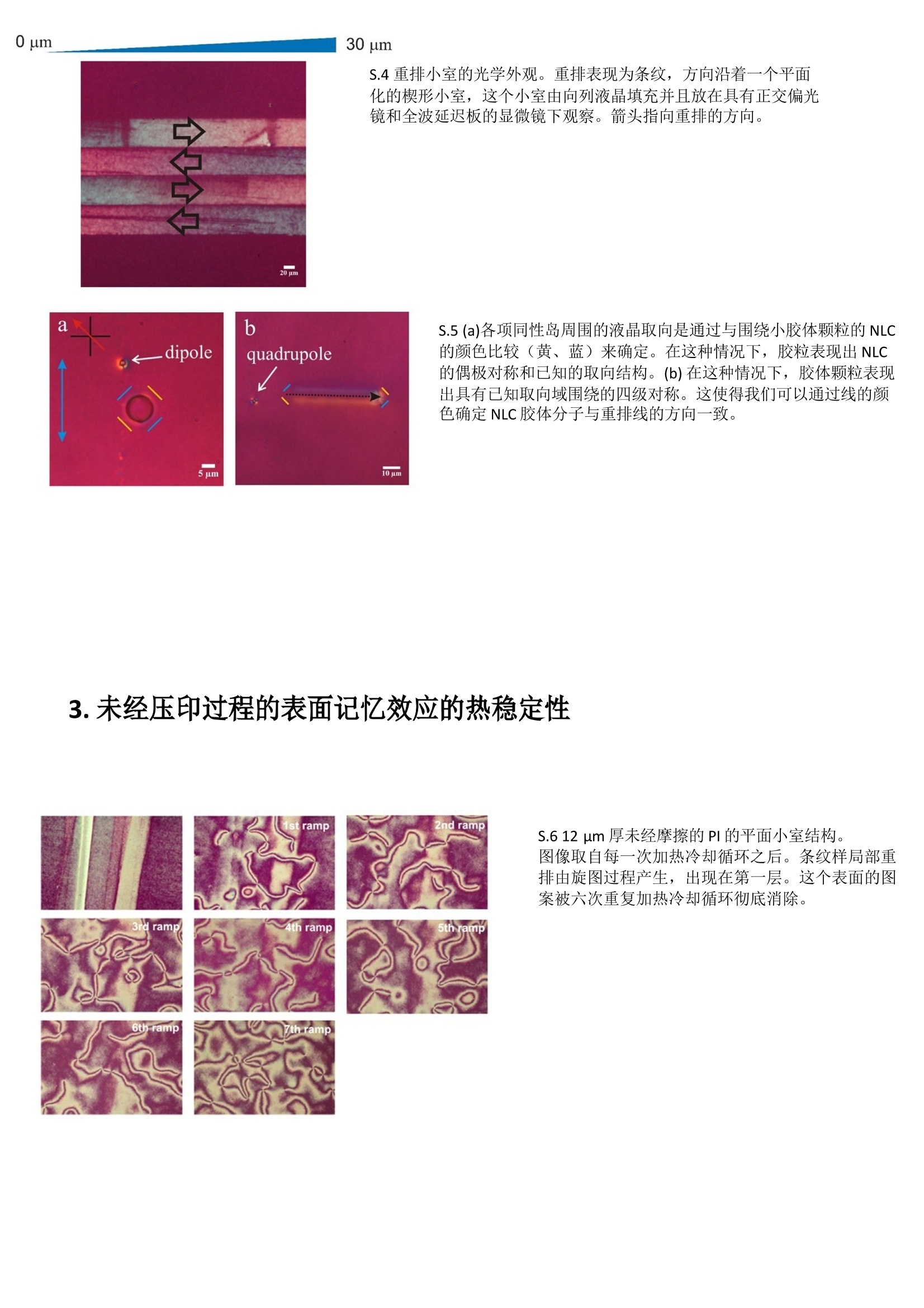
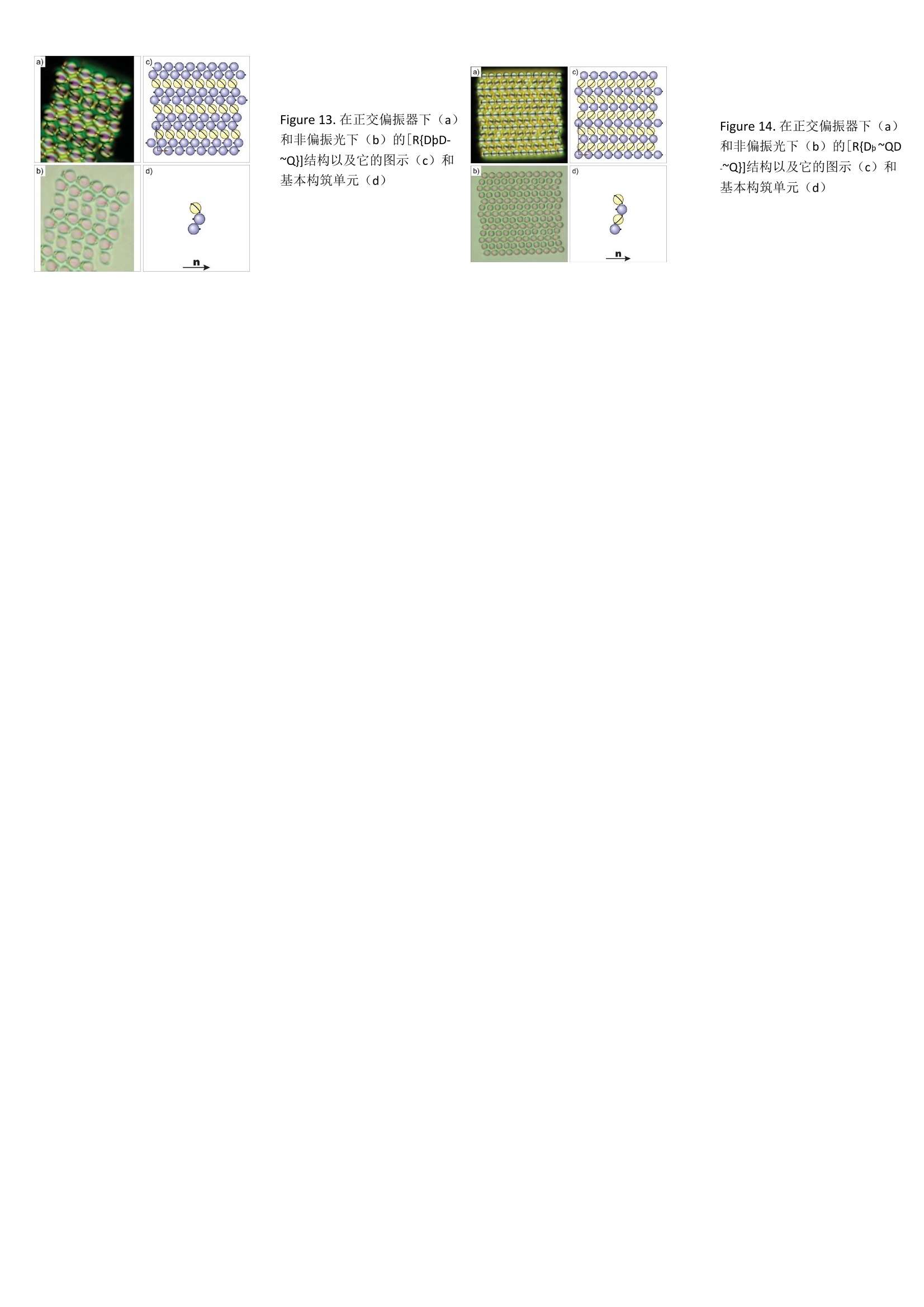
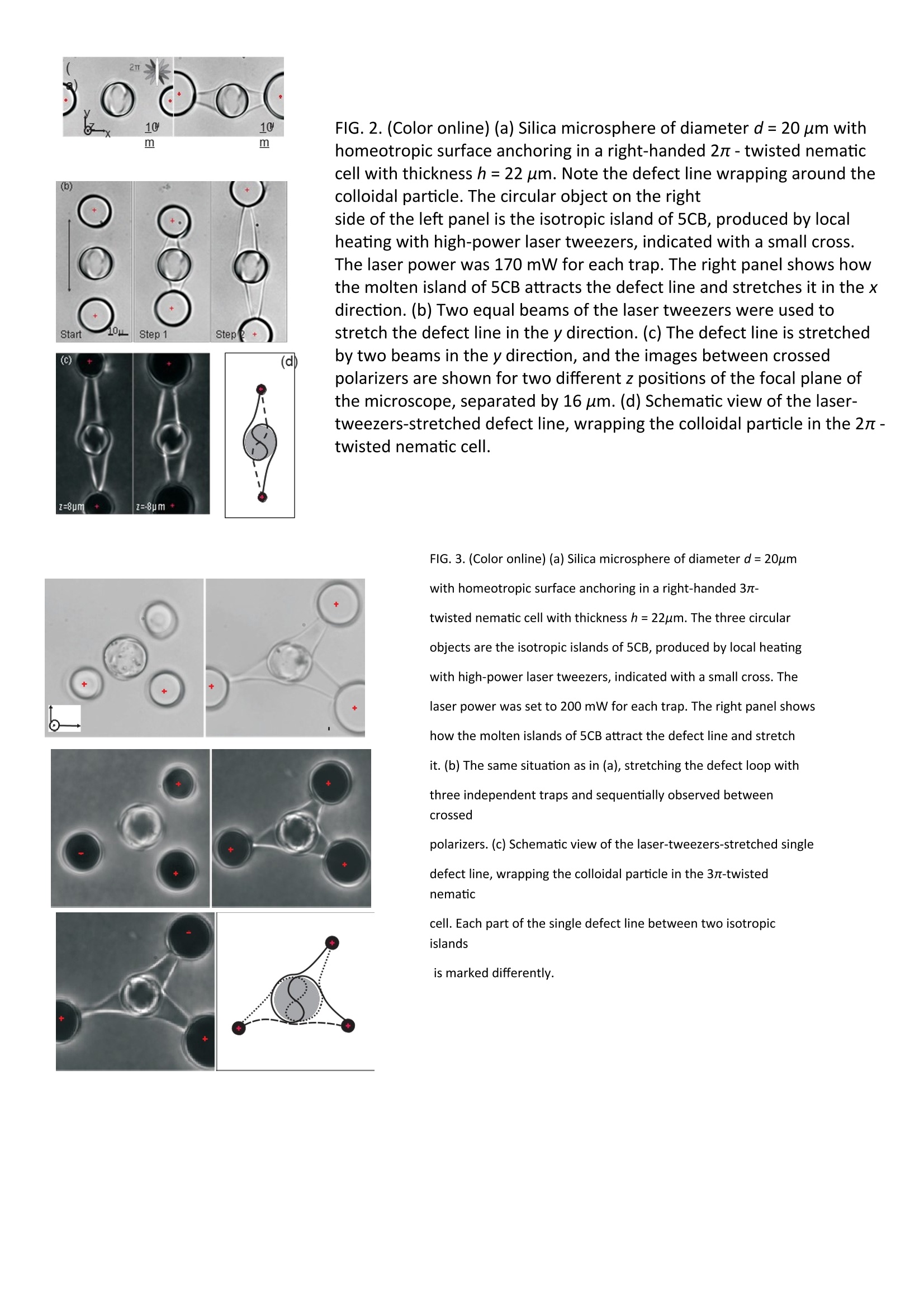
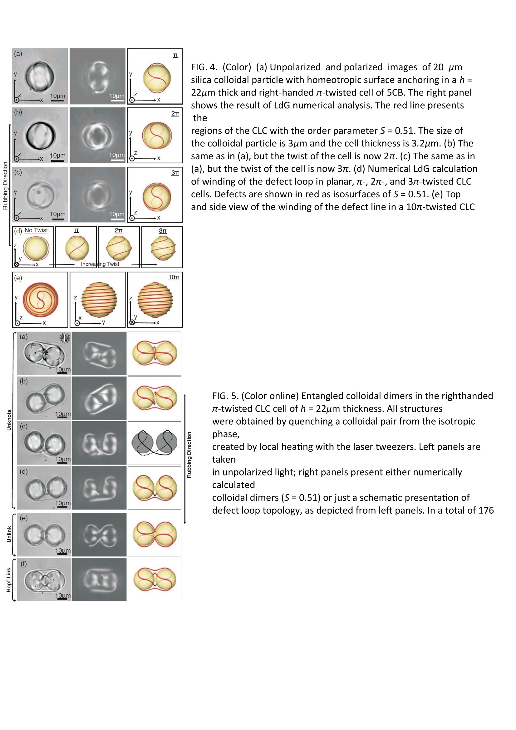
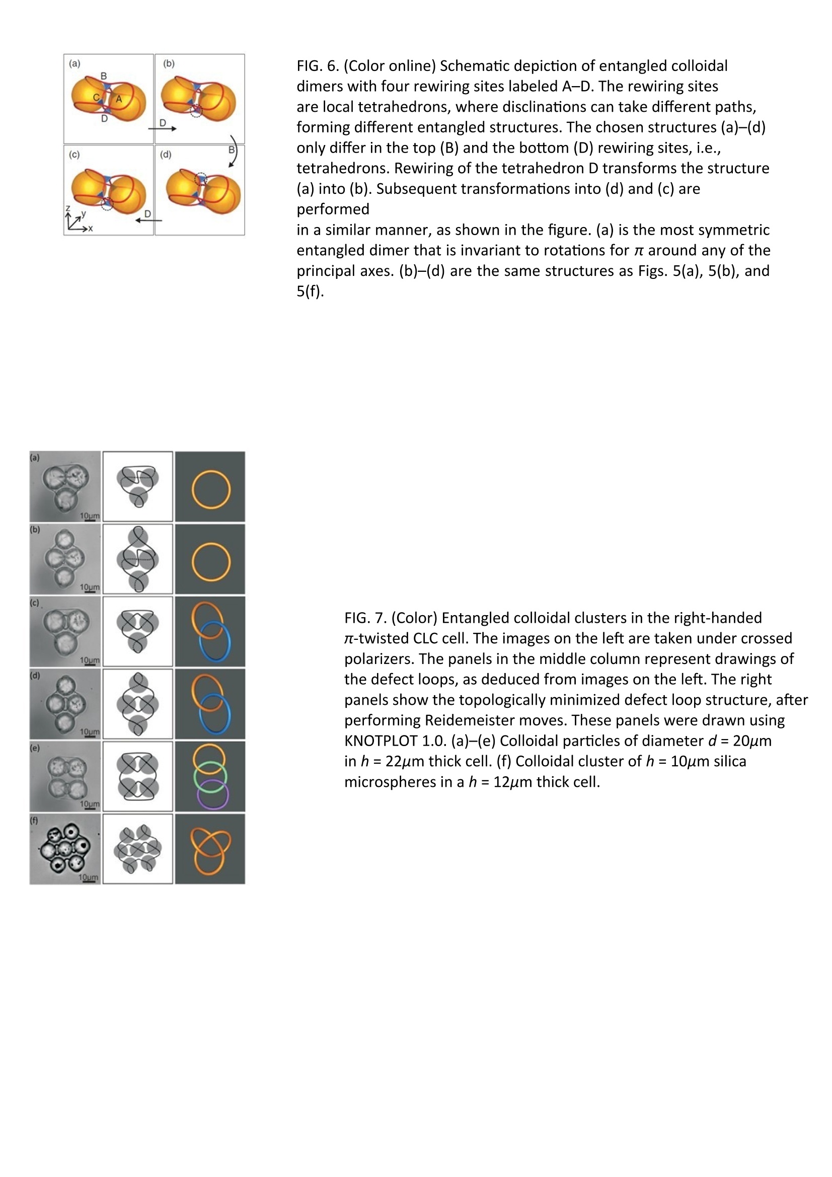
THE EUROPEAN PHYSICAL JOURNAL Light-driven oscillations of entangled nematic colloidal chains 缠绕的向列胶体链的光驱动振动 (2010) 摘要:光镊被用于驱动向列液晶5CB中的缠绕胶体链的振动。光驱动振动的振幅和相位决定了单个胶体颗粒的运动。4.8μm的二氧化硅粒子的集体运动对超过0.5赫兹的驱动频率高度阻尼。此结果与一个有效的一个有效的珠弹簧模型进行了比较,其中的弹性耦合粒子的运动被液体黏度阻碍和流体力学耦合。理论和实验具有定性的一致性。 Fig. 1. (a)由两个光阱拉伸的缠绕的双曲缺陷型胶体链。胶体颗粒1上的左侧光阱是固定的,右侧在胶体颗粒4上的光阱以固定频率和振幅做简谐振动。 (b)记录的在右侧光阱以频率0.2Hz,振幅0.75μm振动时第 三个颗粒X3的水平位置。 Fig. 2. (a) 测得的前三个胶体颗粒链的相对振幅对频率的依赖性和拟合的分析结果(曲 线)。(b) 测得的前三个胶体颗粒链的相对相位对频率的依赖性和拟合的分析结果(曲线) Fig. 3.测量光阱和具有Saturn环的胶体颗粒间的弹性系数Kt .(a) 在实验开始时使用了两个光阱. 第一个光阱提供颗粒与光阱焦点间的吸引力,另一个光阱固定住这个颗粒. 然后右侧光阱关闭,颗粒被吸引进左侧光阱。(b) 作为分离函数的光阱与胶体颗粒间的光力。通过图的斜率确定光阱最终的弹性常数。 Fig. 4. (a) 振动的纠缠胶体颗粒链的珠子-弹簧模型。第一个颗粒通过弹簧样的连接Kt与光阱相互作用.注意颗粒间的弹簧样连接。γx 是颗粒运动的有效斯托克斯黏度系数,Γ 是相邻颗粒间的流体力学相互作用. 像在实验中一样,4号颗粒以振幅X4和频率ω驱动简谐振动。(b) 双曲型缺陷胶体链, 如Landau-de Gennes方法计算的一样. 缺陷以向列有序参数S = 0.50的等值面展示。 2015 In situ laser-imprinted surface realignment of a nematic liquid crystal 向列液晶的原位激光压印表面重排 我们的实验使用了一种焗油搞的N-I转变温度的液晶,因为在PI层上活的压印效果,我们需要使用相对强的激光能量(400到800mw)。在这种情况下,使用普通的液晶,例如5CB,将不可能控制重排并使之局限在小室一侧的玻璃。如S2所示,在5CB中高功率激光产生的各向同性岛过大并会导致缺陷。 使用lambda延迟板来测量液晶取向(red plate) 由不同激光能量在填充5CB的小室中生成的各向同性岛。蓝色 双箭头表明了初始摩擦方向; 黑线是极化方向, 和分析器,红箭头是延迟板(全波)光学轴心方向。 液晶和延迟板在入射白光上的正交偏光镜效应的示意液晶沿着偏光镜的方向,延迟板(l=530nm) 的光轴指向4 有白光中的绿光实现线性偏振光,并且被偏光镜阻挡, 是红光。b) 如果液晶沿着延迟板光轴的方向,延迟会增光被阻挡,最终光是蓝色。c) 如果液晶转向延迟板光轴向,延迟会减少,蓝光被阻挡,透过光是黄光。 重排小室的光学外观。重排表现为条纹,方向沿着一个平面化的楔形小室,这个小室由向列液晶填充并且放在具有正交偏光镜和全波延迟板的显微镜下观察。箭头指向重排的方向。 (a)各项同性岛周围的液晶取向是通过与围绕小胶体颗粒的NLC 的颜色比较(黄、蓝)来确定。在这种情况下,胶粒表现出NLC 的偶极对称和已知的取向结构。(b) 在这种情况下,胶体颗粒表现出具有已知取向域围绕的四级对称。这使得我们可以通过线的颜色确定NLC胶体分子与重排线的方向一致。 未经压印过程的表面记忆效应的热稳定性 12 μm厚未经摩擦的PI的平面小室结构。 图像取自每一次加热冷却循环之后。条纹样局部重排由旋图过程产生,出现在第一层。这个表面的图案被六次重复加热冷却循环彻底消除。 Aresis 2009 Langmuir---Design of 2D Binary Colloidal Crystals in a Nematic Liquid Crystal 在一种向列液晶中设计二元二维胶体晶体 在本文中,我们研究了一种分散在向列液晶中的,具有正常表面边界条件的,偶极和四级胶体颗粒的二元二维系统的定向自组装。使用激光镊,我们组装了多种稳定的二维胶体晶体结构。在所有分析的结构中,那些颗粒它们的表面处理和小室条件是相同的,这使得我们在大量粒子存在的情况下能够系统地跟踪胶体组装的演变。我们提出了一种在液晶介质中分子自组装和胶体微球组织的相似性,延伸了在不同复杂性程度上设计胶体晶体结构的策略。 本文目的在于研究一种分散在向列液晶中的具有正常表面边界条件的偶极和四极胶体颗粒的二元二维系统的定向自组装。通过使用光镊和应用原子间键的类比,我们实现了各种各样的胶体二维晶体结构,并提出了一种它们组装的一般性策略和设计规则。 Figure 1. 图示角度依赖的,胶体对间相互作用 偶极-偶极相互作用, (b) 偶极和四极 (c) 四极-四极相互作用terms. 黑点是双曲型刺猬缺陷,黑色环是塞坦环缺陷. 中间的颗粒为参照,剩余颗粒沿着参比颗粒的最强吸引力方向排列。在红色阴影区域,两两相互作用是排斥的。 Figure 2. 图示4μm胶体在处于正交偏振器(第一行)和非偏振光(第二行)之间的几种基本重排: (a, b) 只具有偶极取向配置的颗粒; (c, d, e, f, g, h) 具备偶极和四极配置的混合颗粒。(i)只具有四极取向配置的颗粒。使用类似化学公式来描述每一种排 列。我们假设偶极胶体颗粒的偶极矩是正的,此时它所伴随的双曲型刺猬缺陷的方向与颗粒的X轴方向一致。 Figure 3. 在正交偏振器下 (a)和非偏振光下(b)的 4μm胶体颗粒[D+Q] 结构以及它的图示(c)和基本构筑单元(d) Figure 5. 在正交偏振器下(a) 和非偏振光下(b)的[D+QD2 -]结构以及它的图示(c)和 基本构筑单元(d) Figure 4. 在正交(水平和垂直)偏振器下(a)和非偏振光下(b)的[D+QD-] 结构以及它的图示(c)和基本构筑单元(d) Figure 6. 在正交偏振器下(a) 和非偏振光下(b)的[D+QD2 -]结构以及它的图示(c)和基 本构筑单元(d) Figure7. 在正交偏振器下(a) 和非偏振光下(b)的[D+Q2D-] 结构以及它的图示(c)和基本构筑单元(d) Figure 9. 在正交偏振器下(a)和非偏振光下(b)的[D10þD10-Q4]结构以及它的图示(c)和基本构筑单元(d) Figure 8. 在正交偏振器下(a) 和非偏振光下(b)的[D+Q3D-] 结构以及它的图示(c)和基本构筑单元(d) Figure 10. 在正交偏振器下(a)和非偏振光下(b)的R{D+Q}结构以及它的图示(c)和基本构筑单元(d) Figure 13. 在正交偏振器下(a) 和非偏振光下(b)的[R{DþD- ~Q}]结构以及它的图示(c)和基本构筑单元(d) Figure 14. 在正交偏振器下(a) 和非偏振光下(b)的[R{Dþ ~QD -~Q}]结构以及它的图示(c)和 基本构筑单元(d) Aresis 2011 PHYSICAL REVIEW---Colloidal entanglement in highly twisted chiral nematic colloids- Twisted loops, Hopf links, and trefoil knots 高度扭曲的手性向列胶体中的胶态缠绕——扭曲环,霍普夫链和三叶草节 The topology and geometry of closed defect loops is studied in chiral nematic colloids with variable chirality. The colloidal particles with perpendicular surface anchoring of liquid crystalline molecules are inserted in a twisted nematic cell with the thickness that is only slightly larger than the diameter of the colloidal particle. The total twist of the chiral nematic structure in cells with parallel boundary conditions is set to 0, π , 2π , and 3π , respectively. We use the laser tweezers to discern the number and the topology of the −1/2 defect loops entangling colloidal particles. For a single colloidal particle, we observe that a single defect loop is winding around the particle, with the winding pattern being more complex in cells with higher total twist. We observe that colloidal dimers and colloidal clusters are always entangled by one or several −1/2 defect loops. For colloidal pairs in π -twisted cells, we identify at least 17 different entangled structures, some of them exhibiting linked defect loops-Hopf link. Colloidal entanglement is even richer with a higher number of colloidal particles, where we observe not only linked, but also colloidal clusters knotted into the trefoil knot. The experiments are in good agreement with numerical modeling using Landau-de Gennes theory coupled with geometrical and topological considerations using the method of tetrahedral rotation. FIG. 1. (Color online) (a) Silica microsphere of diameter d = 20 μm with homeotropic surface anchoring in a ( ( S 1 S S )right-handed π - twisted nematic cell with thickness h = 22 μm. Note the defect line wrapping around the colloidal particle. The circular object on the right side of the left panel is the isotropic island of 5CB, produced by local heating with high-power laser tweezers, indicated with a small cross. The laser power was 100 mW for each trap. Right panel shows how the molten island of 5CB captures the defect line and stretches it in the x direction. (b) Two equal beams of the laser tweezers were used to stretch the defect line FIG. 2. (Color online) (a) Silica microsphere of diameter d = 20 μm with homeotropic surface anchoring in a right-handed 2π - twisted nematic cell with thickness h = 22 μm. Note the defect line wrapping around the colloidal particle. The circular object on the right side of the left panel is the isotropic island of 5CB, produced by local heating with high-power laser tweezers, indicated with a small cross. The laser power was 170 mW for each trap. The right panel shows how the molten island of 5CB attracts the defect line and stretches it in the x direction. (b) Two equal beams of the laser tweezers were used to stretch the defect line in the y direction. (c) The defect line is stretched by two beams in the y direction, and the images between crossed polarizers are shown for two different z positions of the focal plane of the microscope, separated by 16 μm. (d) Schematic view of the laser- tweezers-stretched defect line, wrapping the colloidal particle in the 2π - twisted nematic cell. FIG. 3. (Color online) (a) Silica microsphere of diameter d = 20μm with homeotropic surface anchoring in a right-handed 3π- twisted nematic cell with thickness h = 22μm. The three circular objects are the isotropic islands of 5CB, produced by local heating with high-power laser tweezers, indicated with a small cross. The laser power was set to 200 mW for each trap. The right panel shows how the molten islands of 5CB attract the defect line and stretch it. (b) The same situation as in (a), stretching the defect loop with three independent traps and sequentially observed between crossed polarizers. (c) Schematic view of the laser-tweezers-stretched single defect line, wrapping the colloidal particle in the 3π-twisted nematic cell. Each part of the single defect line between two isotropic islands is marked differently. FIG. 4. (Color) (a) Unpolarized and polarized images of 20 μm silica colloidal particle with homeotropic surface anchoring in a h = 22μm thick and right-handed π-twisted cell of 5CB. The right panel shows the result of LdG numerical analysis. The red line presents the regions of the CLC with the order parameter S = 0.51. The size of the colloidal particle is 3μm and the cell thickness is 3.2μm. (b) The same as in (a), but the twist of the cell is now 2π. (c) The same as in (a), but the twist of the cell is now 3π. (d) Numerical LdG calculation of winding of the defect loop in planar, π-, 2π-, and 3π-twisted CLC cells. Defects are shown in red as isosurfaces of S = 0.51. (e) Top and side view of the winding of the defect line in a 10π-twisted CLC FIG. 5. (Color online) Entangled colloidal dimers in the righthanded π-twisted CLC cell of h = 22μm thickness. All structures were obtained by quenching a colloidal pair from the isotropic phase, created by local heating with the laser tweezers. Left panels are taken in unpolarized light; right panels present either numerically calculated colloidal dimers (S = 0.51) or just a schematic presentation of defect loop topology, as depicted from left panels. In a total of 176 FIG. 6. (Color online) Schematic depiction of entangled colloidal dimers with four rewiring sites labeled A–D. The rewiring sites are local tetrahedrons, where disclinations can take different paths, forming different entangled structures. The chosen structures (a)–(d) only differ in the top (B) and the bottom (D) rewiring sites, i.e., tetrahedrons. Rewiring of the tetrahedron D transforms the structure (a) into (b). Subsequent transformations into (d) and (c) are performed in a similar manner, as shown in the figure. (a) is the most symmetric entangled dimer that is invariant to rotations for π around any of the principal axes. (b)–(d) are the same structures as Figs. 5(a), 5(b), and 5(f). FIG. 7. (Color) Entangled colloidal clusters in the right-handed π-twisted CLC cell. The images on the left are taken under crossed polarizers. The panels in the middle column represent drawings of the defect loops, as deduced from images on the left. The right panels show the topologically minimized defect loop structure, after performing Reidemeister moves. These panels were drawn using KNOTPLOT 1.0. (a)–(e) Colloidal particles of diameter d = 20μm in h = 22μm thick cell. (f) Colloidal cluster of h = 10μm silica microspheres in a h = 12μm thick cell.
确定


还剩14页未读,是否继续阅读?

艾锐斯科技(北京)有限公司为您提供《液晶中设计排列检测方案(光学镊子)》,该方案主要用于化工原料中设计排列检测,参考标准--,《液晶中设计排列检测方案(光学镊子)》用到的仪器有
相关方案
更多