


PROBLEM:
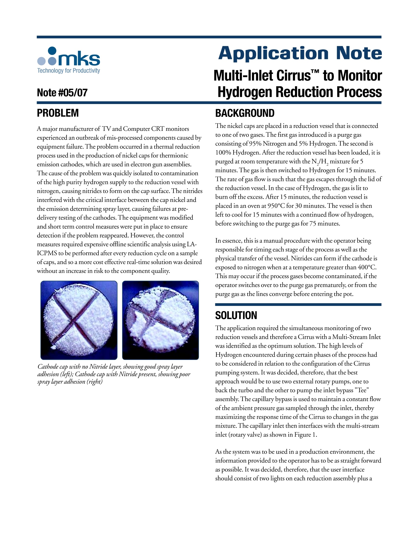
A major manufacturer of TV and Computer CRT monitors
experienced an outbreak of mis-processed components caused by
equipment failure. The problem occurred in a thermal reduction
process used in the production of nickel caps for thermionic
emission cathodes, which are used in electron gun assemblies.
The cause of the problem was quickly isolated to contamination
of the high purity hydrogen supply to the reduction vessel with
nitrogen, causing nitrides to form on the cap surface. The nitrides
interfered with the critical interface between the cap nickel and
the emission determining spray layer, causing failures at predelivery
testing of the cathodes. The equipment was modified
and short term control measures were put in place to ensure
detection if the problem reappeared. However, the control
measures required expensive offline scientific analysis using LAICPMS
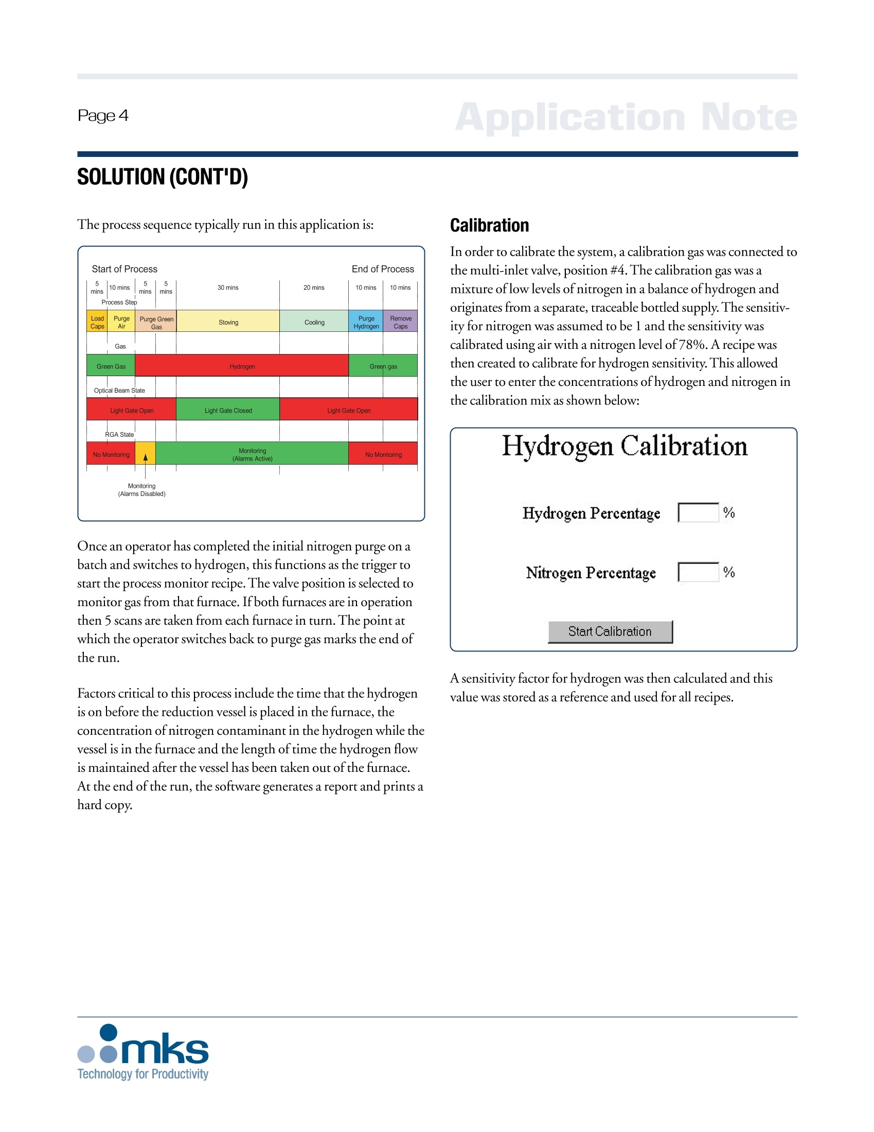
to be performed after every reduction cycle on a sample
of caps, and so a more cost effective real-time solution was desired
without an increase in risk to the component quality.
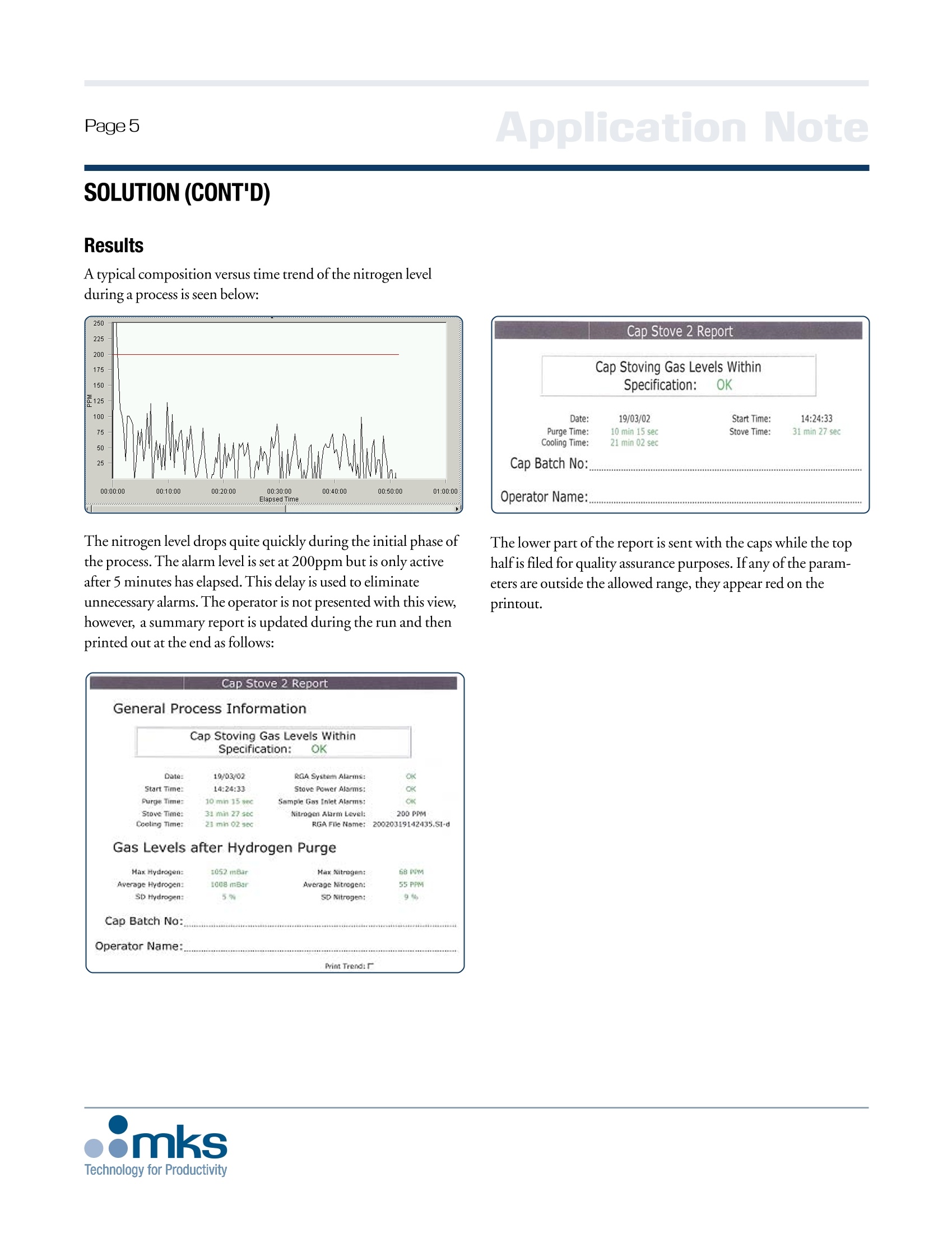
方案详情

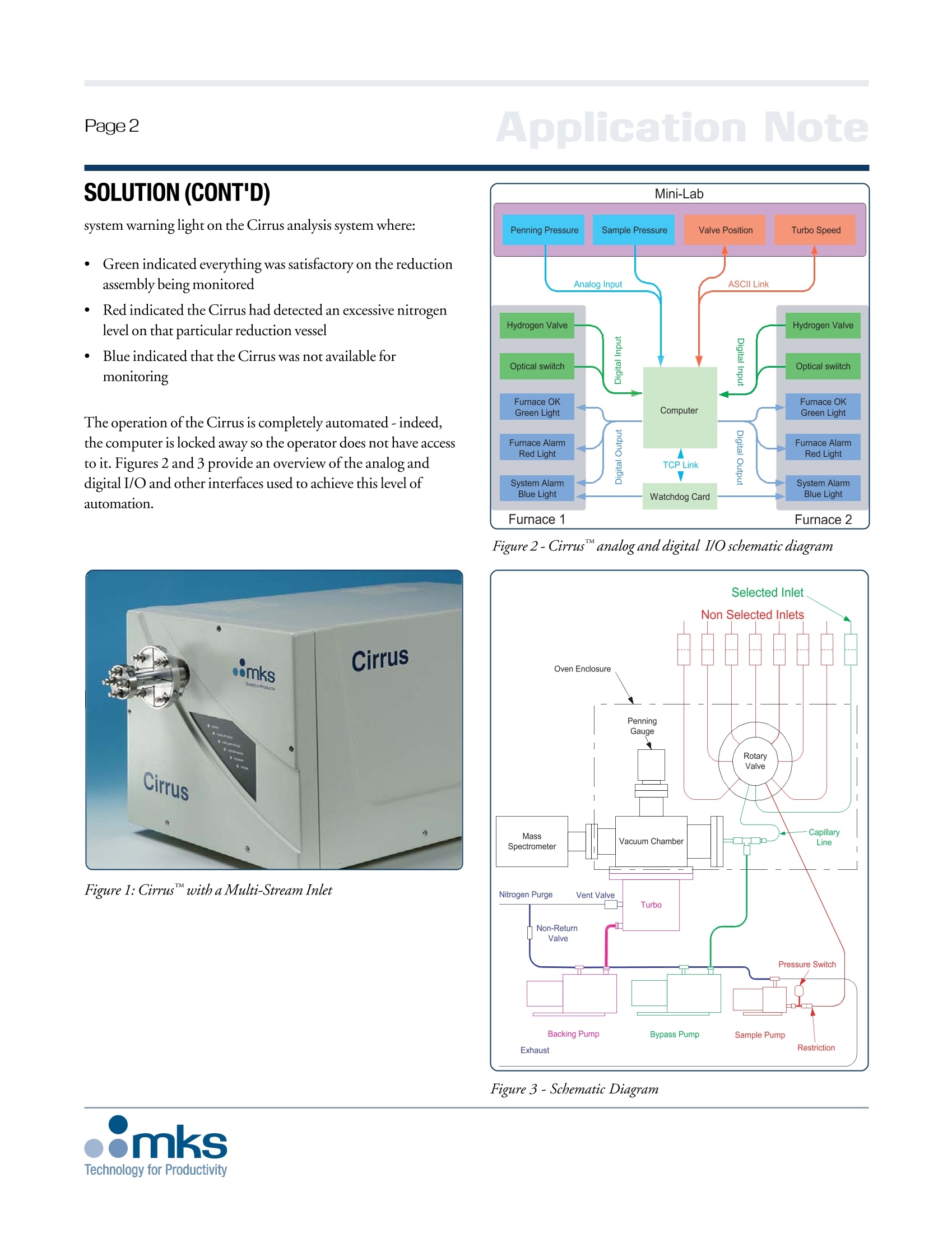
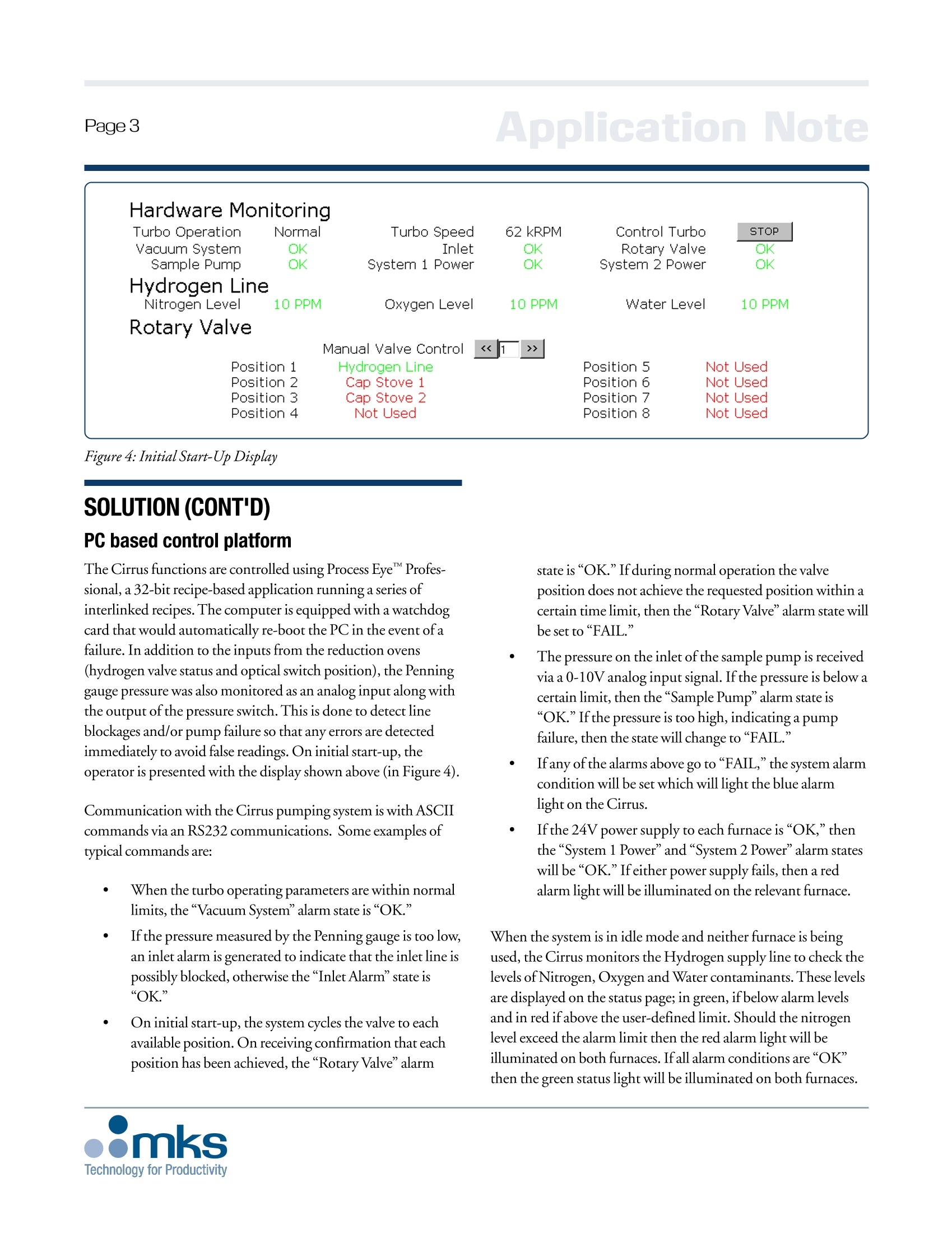
Page3 Note #05/07PROBLEM A major manufacturer of TV and Computer CRT monitorsexperienced an outbreak of mis-processed components caused byequipment failure. The problem occurred in a thermal reductionprocess used in the production of nickel caps for thermionicemission cathodes, which are used in electron gun assemblies.The cause of the problem was quickly isolated to contaminationof the high purity hydrogen supply to the reduction vessel withnitrogen, causing nitrides to form on the cap surface. The nitridesinterfered with the critical interface between the cap nickel andthe emission determining spray layer, causing failures at pre-delivery testing of the cathodes. The equipment was modifiedand short term control measures were put in place to ensuredetection if the problem reappeared. However, the controlmeasures required expensive offline scientific analysis using LA-ICPMS to be performed after every reduction cycle on a sampleof caps,and so a more cost effective real-time solution was desiredwithout an increase in risk to the component quality. Cathode cap with no Nitride layer, showing good spray layeradhesion (left); Cathode cap with Nitride present, showing poorspray layer adhesion (right) Application NoteMulti-Inlet Cirrus to MonitorHydrogen Reduction Process BACKGROUND The nickel caps are placed in a reduction vessel that is connectedto one of two gases. The first gas introduced is a purge gasconsisting of 95% Nitrogen and 5% Hydrogen. The second is100% Hydrogen. After the reduction vessel has been loaded, it ispurged at room temperature with the N,/H, mixture for 5minutes. The gas is then switched to Hydrogen for 15 minutes.The rate of gas flow is such that the gas escapes through the lid ofthe reduction vessel. In the case of Hydrogen, the gas is lit toburn off the excess. After 15 minutes, the reduction vessel isplaced in an oven at 950°C for 30 minutes.The vessel is thenleft to cool for 15 minutes with a continued flow of hydrogen,before switching to the purge gas for 75 minutes. In essence, this is a manual procedure with the operator beingresponsible for timing each stage ofthe process as well as thephysical transfer of the vessel. Nitrides can form if the cathode isexposed to nitrogen when at a temperature greater than 400°℃.This may occur if the process gases become contaminated, if theoperator switches over to the purge gas prematurely, or from thepurge gas as the lines converge before entering the pot. SOLUTION The application required the simultaneous monitoring oftworeduction vessels and therefore a Cirrus with a Multi-Stream Inletwas identified as the optimum solution. The high levels ofHydrogen encountered during certain phases of the process hadto be considered in relation to the configuration of the Cirruspumping system. It was decided, therefore, that the bestapproach would be to use two external rotary pumps,one toback the turbo and the other to pump the inlet bypass "Tee"assembly. The capillary bypass is used to maintain a constant flowof the ambient pressure gas sampled through the inlet, therebymaximizing the response time of the Cirrus to changes in the gasmixture. The capillary inlet then interfaces with the multi-streaminlet (rotary valve) as shown in Figure 1. As the system was to be used in a production environment, theinformation provided to the operator has to be as straight forwardas possible. It was decided, therefore, that the user interfaceshould consist of two lights on each reduction assembly plus a SOLUTION (CONT'D) system warning light on the Cirrus analysis system where: ·CGreen indicated everything was satisfactory on the reductionassembly being monitored RRed indicated the Cirrus had detected an excessive nitrogenlevel on that particular reduction vessel Blue indicated that the Cirrus was not available formonitoring The operation of the Cirrus is completely automated- indeed,the computer is locked away so the operator does not have accessto it. Figures 2 and 3 provide an overview of the analog anddigital I/O and other interfaces used to achieve this level ofautomation. Figure 1: Cirruswith a Multi-Stream Inlet Figure 2-Cirrus analog and digital I/O schematic diagram Hardware Monitoring Turbo Operation Normal Turbo Speed 62 kRPM Control Turbo STOP Vacuum System OK Inlet OK Rotary Valve OK Sample Pump OK System 1 Power OK System 2 Power OK Hydrogen Line Nitrogen Level 10 PPM Oxygen Level 10 PPM Water Level 10 PPM Rotary Valve Manual Valve Control << >> Position 1 Hydrogen Line Position 5 Not Used Position 2 Cap Stove 1 Position 6 Not Used Position 3 Cap Stove 2 Position 7 Not Used Position 4 Not Used Position 8 Not Used SOLUTION (CONT'D)PC based control platform The Cirrus functions are controlled using Process EyeProfes-sional, a 32-bit recipe-based application running a series ofinterlinked recipes. The computer is equipped with a watchdogcard that would automatically re-boot the PC in the event of afailure. In addition to the inputs from the reduction ovens(hydrogen valve status and optical switch position), the Penninggauge pressure was also monitored as an analog input along withthe output of the pressure switch. This is done to detect lineblockages and/or pump failure so that any errors are detectedimmediately to avoid false readings. On initial start-up, theoperator is presented with the display shown above (in Figure 4). Communication with the Cirrus pumping system is with ASCIIcommands via an RS232 communications. Some examples oftypical commands are: When the turbo operating parameters are within normallimits, the “Vacuum System"alarm state is“OK." If the pressure measured by the Penning gauge is too low,an inlet alarm is generated to indicate that the inlet line ispossibly blocked, otherwise the“Inlet Alarm'state is"OK." On initial start-up, the system cycles the valve to eachavailable position. On receiving confirmation that eachposition has been achieved, the “Rotary Valve"alarm state is “OK." If during normal operation the valveposition does not achieve the requested position within acertain time limit, then the"Rotary Valve"alarm state willbe set to“FAIL.” The pressure on the inlet of the sample pump is receivedvia a 0-10V analog input signal. Ifthe pressure is below acertain limit, then the“Sample Pumpalarm state is“OK." If the pressure is too high, indicating a pumpfailure, then the state will change to “FAIL.” Ifany of the alarms above go to “FAIL," the system alarmcondition will be set which will light the blue alarmlight on the Cirrus. If the 24V power supply to each furnace is “OK,”thenthe “System 1 Power”and“System 2 Power”alarm stateswill be “OK."Ifeither power supply fails, then a redalarm light will be illuminated on the relevant furnace. When the system is in idle mode and neither furnace is beingused, the Cirrus monitors the Hydrogen supply line to check thelevels of Nitrogen, Oxygen and Water contaminants. These levelsare displayed on the status page; in green, if below alarm levelsand in red if above the user-defined limit. Should the nitrogenlevel exceed the alarm limit then the red alarm light will beilluminated on both furnaces. If all alarm conditions are“OK”then the green status light will be illuminated on both furnaces. The process sequence typically run in this application is: Once an operator has completed the initial nitrogen purge on abatch and switches to hydrogen, this functions as the trigger tostart the process monitor recipe. The valve position is selected tomonitor gas from that furnace. Ifboth furnaces are in operationthen 5 scans are taken from each furnace in turn. The point atwhich the operator switches back to purge gas marks the end ofthe run. Factors critical to this process include the time that the hydrogenis on before the reduction vessel is placed in the furnace, theconcentration of nitrogen contaminant in the hydrogen while thevessel is in the furnace and the length of time the hydrogen flowis maintained after the vessel has been taken out of the furnace.At the end of the run, the software generates a report and prints ahard copy. Calibration In order to calibrate the system, a calibration gas was connected tothe multi-inlet valve, position #4. The calibration gas was amixture of low levels of nitrogen in a balance of hydrogen andoriginates from a separate, traceable bottled supply. The sensitiv-ity for nitrogen was assumed to be 1 and the sensitivity wascalibrated using air with a nitrogen level of 78%. A recipe wasthen created to calibrate for hydrogen sensitivity. This allowedthe user to enter the concentrations of hydrogen and nitrogen inthe calibration mix as shown below: A sensitivity factor for hydrogen was then calculated and thisvalue was stored as a reference and used for all recipes. Page 5 Application Note SOLUTION (CONT'D) Results A typical composition versus time trend of the nitrogen levelduring a process is seen below: The nitrogen level drops quite quickly during the initial phase ofthe process.The alarm level is set at 200ppm but is only activeafter 5 minutes has elapsed.This delay is used to eliminateunnecessary alarms. The operator is not presented with this view,however, a summary report is updated during the run and thenprinted out at the end as follows: The lower part of the report is sent with the caps while the tophalf is filed for quality assurance purposes. If any ofthe param-eters are outside the allowed range, they appear red on theprintout. Application Note BENEFITS The customer has observed significant benefits in several keyareas: Significantly improved process reproducibility and hasvirtually eliminated batch-to-batch variability Eliminated undetected operator induced processvariations - Aided in operator training issues by identifying andquantifying operator errors, by operator, over time Allowed for additional process optimizations to occurthrough utilization of extra data acquisition capabili-ties and PC control of the Cirrus Eliminated the expense of routine testing of thecomponents, resulting in a savings of more than$120,000 annually Reduced the component lead time through the use ofin-line real-time detection Utilizing the Cirrus with its powerful Process Eye Professionalsoftware has led to further use of process monitors as a diagnosticand process optimization tool. This customer also purchasedprocess monitors powered by Process Eye Professional in theirvacuum sputtering areas to monitor the vacuum quality and todetect and quantify machine and operator variability. ( For further information, c all your local MKS Sales Engineer o r contact the M KS Applications Engineering Group at 800-227-8766. C irrusa n d Process Eyeare trademarks of MKS Instruments, Inc., Andover, MA. ) App. Note 05/07-1/08 Cowley Way ( MKS Global H ea d q u arters2 Tech Drive, Suite 201 Andover, MA 01810978.645.5500 800.227.8766 (within USA) www.mksinst.com ) Technology for Productivity
确定

还剩4页未读,是否继续阅读?

万机仪器(上海)有限公司为您提供《氢还原反应过程监测- MKS Cirrus 2》,该方案主要用于其他中--检测,参考标准--,《氢还原反应过程监测- MKS Cirrus 2》用到的仪器有
相关方案
更多