资料下载: Download Off-Axis Parabolic Mirrors Datasheet (PDF, 164 KB)
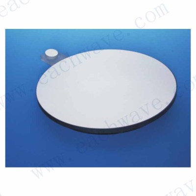
Parabolic mirrors are the most common type of aspherical mirrors used in optical instruments. They are free from spherical aberrations, and thus focus the parallel beam to a point or point source to infinity.
In many optical systems it is not necessary to use aperture that is completely rotationally symmetric. On the other hand, in some applications the central part of the mirror obscures the beam path and therefore is a disaster. For such systems, off-axis mirrors offer many advantages versus the traditional paraboloids.
Main applications of off-axis parabolic mirrors are as follows:
Target simulators
Collimators
MTF measuring systems and other optics test devices
Spectroscopic and FTIR systems
Radiometers
Beam expanders
Laser divergence measuring systems
Key advantages of off-axis parabolic mirrors
Use of off-axis optics allows optical engineers to achieve the following advantages:
Minimize system sizes
Minimize system weight
Both “wedged” and equi-thick mirrors are available
Minimize system cost
All this results in maximization of system efficiency and marketability.
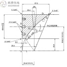
How to specify OAP mirror

Fig. 1 Off-axis parabolic mirror draft.
Description to the draft.
Parent focal length (PFL) is the focal length of the parent paraboloid. It defines the shape of the surface as Z=R^2/4*PFL, where R is radial distance from vertex and Z is surface sagitta.
Slant Focal Length (SFL) is the distance between OAP mechanical center and parabola focus. This value may be calculated from PFL and vice versa.
Optical Centerline is the line parallel to parent parabola optical axis and coming through the mechanical center of OAP.
Zonal Radius (ZR) is the distance between parent parabola optical axis and optical centerline of the OAP.
Off-axis Distance (OAD) is the distance from parent parabola optical axis to inner edge of OAP. This value may be calculated from ZR and vice versa.
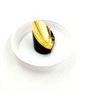
Adjust flat is commonly glued to OAP. It is perpendicular to parent parabola optical axis (and therefore to OAP centerline) and helps greatly to adjust OAP in the optical system.
To fully describe OAP one has to specify 5 parameters:
PFL (or SFL),
ZR (or OAD),
CA (clear aperture),
SA (surface accuracy),
and SQ (surface quality).
Auxiliary parameters are:
preferable mechanical size and thickness (if not specified we state Diameter = CA+10 mm and Thickness = Diameter/8),
preferable material (if not specified we state LK-7 optical glass – Russian analogue of Pyrex),
and coating type (if not specified we state protected aluminum).
Key data for OAP mirrors we produce
Typical material is LK-7 (analogue of Pyrex), also AstroSitall CO-115M (analogue of Zerodur), and K8 glass (analogue of BK7) are available on request.
Typical surface accuracy is l/8 at 633 nm PtV, l/40 RMS. Higher precision surfaces may be produced on the request.
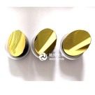
Typical coating is protected Al, other metal (silver or gold) or multilayer dielectric coatings are available on request.
Off-axis angle is up to 45 degrees, typical value is 5-30 degrees.
Focal lengths are from 150 mm up to 12 meters. Typical value is 0.5-2 meters.
Diameters are up to 640 mm. Typical values are 100-400 mm.
All these parameters are not independent. For example longer focal length allows better SA and longer ZR makes for lower SA.
Documentation
Together with each mirror we supply a certificate that shows SA, SQ, measured data for PFL and ZR, and the mechanical sizes. Interferometer graph of the surface, calculated surface error profile and coating reflection spectrum are attached to this certificate. Sample interferometer graph, surface error profile and coating spectrum are shown below. These are for CA 8” mirror with ZR 7” and FL40.

Fig. 2 Typical interferometer graph of OAP mirror.

Fig. 3 Surface error profile reconstruction.
Wave front analysis
Units of deformations measuring: microns
Wavelength: 0.633 μm
Reference surface: sphere
Subtracted aberrations:
Form of zonal error - Zernike polynomial
Parameters of regular errors
D = -0.000 Lx = 0.000 Ly = -0.000 C = 0.000 RMS(W) = 0.009
A = 0.013 FIA = 41.300 PV = 0.025 RMS(W-A) = 0.007 FA = 0.361
B0 = 0.007 PV = 0.011 RMS(W-Z) = 0.008 FZ = 0.137
B2 = -0.043
B4 = 0.043
C = 0.020 FIC = 5.327 PV = 0.013 RMS(W-C) = 0.008 FC = 0.074
Local errors
| PV = 0.037RMS(M) = 0.006Characteristics of wavefrontRMSMINMAXPVSTRLSTRH0.009-0.0230.0320.0550.9980.999 |
 coating")
Short description and key advantages of the technology
The manufacturing technology was developed to supply mirrors cheaper and in higher volume for use in aero/defence applications. Typically, OAPs are made by polishing and slicing-up large on-axis parent paraboloids. Obviously, this “traditional” method is quite expensive, especially when perhaps only 1-2 mirrors are needed. This older method also places heavy restrictions on the range of available combinations of focal lengths and off-axis distances. The other “traditional” method is diamond turning. Its main disadvantages are limitations for substrate materials (metals), lower surface roughness, and accuracy.
Instead of the above-mentioned methods of OAPs production, our OAP facility uses a sophisticated, computer-controlled spot-correction polishing process. It combines advantages of conventional polishing (smooth surface and possibility to use common glasses) and diamond turning (possibility to produce OAP without polishing of full paraboloid). After each polishing run we measure the surface error using large interferometers that precisely simulate current surface error of the OAP mirror. Then the information from the interferometer is transferred to the polisher’s computerized controller, which calculates the optimum location, trajectory and rotation speed of the compact, spot-polishing head.
We name this process retouching. 10,000 square-foot facility is used for this production. A team of highly experienced (and patient!) technicians set up and measure a mirror over and over until it is perfect. Each mirror undergoes typically about 10 cycles of interferometric measurements, followed by retouching. Of course for state-of-the-art mirrors many more cycles are required.
This unique production technology allows us to offer precise optics at very competitive prices.
更多太赫兹元件相关产品
>> 太赫兹透镜
>> 太赫兹偏振片 HDPE
>> 太赫兹线栅偏振片
>> 太赫兹衰减片
>> 太赫兹波片
>> 太赫兹分束镜
>> 太赫兹光谱分光镜
>> 太赫兹棱镜
>> 太赫兹窗片
>> 太赫兹滤波片
离轴抛物镜 Off-Axis Parabolic Mirrors信息由上海屹持光电技术有限公司为您提供,如您想了解更多关于离轴抛物镜 Off-Axis Parabolic Mirrors报价、型号、参数等信息,欢迎来电或留言咨询。
除供应离轴抛物镜 Off-Axis Parabolic Mirrors外,上海屹持光电技术有限公司还可为您提供FTE7000A-DWDM光时域反射计 密集波分复用光时域反射计OTDR、波导型PPLN、传感、探测器用镜片 Optics for Sensors and Detectors等产品,公司有专业的客户服务团队,是您值得信赖的合作伙伴。